AP1710-I5 English Manual
Page 2
... ERRORS OR INACCURACIES THAT MAY APPEAR IN THIS MANUAL, INCLUDING THE PRODUCTS AND SOFTWARE DESCRIBED IN IT. Product Name: AP1710-I5 Manual Revision: First Edition E1304 Release Date: June 2003 ii ASUS AP1710-I5 Product warranty or service will not be extended if: (1) the product is repaired, modified or altered, unless such repair, modification of alteration is defaced or missing. Manual revisions are used...
... ERRORS OR INACCURACIES THAT MAY APPEAR IN THIS MANUAL, INCLUDING THE PRODUCTS AND SOFTWARE DESCRIBED IN IT. Product Name: AP1710-I5 Manual Revision: First Edition E1304 Release Date: June 2003 ii ASUS AP1710-I5 Product warranty or service will not be extended if: (1) the product is repaired, modified or altered, unless such repair, modification of alteration is defaced or missing. Manual revisions are used...
AP1710-I5 English Manual
Page 4
... a circuit different from digital apparatus set out in a residential installation. The use of shielded cables for a Class B digital device, pursuant to the graphics card is no guarantee that may cause harmful interference to assure compliance with FCC regulations. iv ASUS AP1710-I5 This class B digital apparatus complies with the limits for connection of the monitor to Part 15 of the following two...
... a circuit different from digital apparatus set out in a residential installation. The use of shielded cables for a Class B digital device, pursuant to the graphics card is no guarantee that may cause harmful interference to assure compliance with FCC regulations. iv ASUS AP1710-I5 This class B digital apparatus complies with the limits for connection of the monitor to Part 15 of the following two...
AP1710-I5 English Manual
Page 5
... Operation Safety vii Introduction About this guide I-1 Audience I-2 Contents I-2 Conventions I-3 References I-3 System Package Contents I-4 Chapter 1: System Overview System Overview 1-1 1.1 System Features 1-2 1.2 Front Panel Features 1-3 1.3 Rear Panel Features 1-4 1.4 Internal Features 1-5 1.5 LED Table 1-6 Chapter 2: Hardware Reference Hardware Reference 2-1 2.1 Removing and installing chassis cover 2-2 2.2 Motherboard installation 2-4 2.3 Central Processing Unit 2-5 2.4 System Memory 2-9 2.5 Fixed Device Bays 2-12 2.6 Installing a Hard Disk Drive 2-18 User's Manual...
... Operation Safety vii Introduction About this guide I-1 Audience I-2 Contents I-2 Conventions I-3 References I-3 System Package Contents I-4 Chapter 1: System Overview System Overview 1-1 1.1 System Features 1-2 1.2 Front Panel Features 1-3 1.3 Rear Panel Features 1-4 1.4 Internal Features 1-5 1.5 LED Table 1-6 Chapter 2: Hardware Reference Hardware Reference 2-1 2.1 Removing and installing chassis cover 2-2 2.2 Motherboard installation 2-4 2.3 Central Processing Unit 2-5 2.4 System Memory 2-9 2.5 Fixed Device Bays 2-12 2.6 Installing a Hard Disk Drive 2-18 User's Manual...
AP1710-I5 English Manual
Page 6
2.7 Screwless Expansion Card Slot 2-23 2.8 Long Card Support Guide 2-24 2.9 RAID Card 2-25 2.10 Hard Drive Blower 2-26 2.11 Chassis Fan 2-27 2.12 Connecting Cables 2-28 2.13 SCSI Backplane 2-29 Appendix A: Optional chassis roller-wheel Chassis Roller-wheel Installation A-2 Appendix B: Power Modules Redundant Power Modules A-4 Appendix C: Troubleshooting Troubleshooting A-9 vi ASUS AP1710-I5
2.7 Screwless Expansion Card Slot 2-23 2.8 Long Card Support Guide 2-24 2.9 RAID Card 2-25 2.10 Hard Drive Blower 2-26 2.11 Chassis Fan 2-27 2.12 Connecting Cables 2-28 2.13 SCSI Backplane 2-29 Appendix A: Optional chassis roller-wheel Chassis Roller-wheel Installation A-2 Appendix B: Power Modules Redundant Power Modules A-4 Appendix C: Troubleshooting Troubleshooting A-9 vi ASUS AP1710-I5
AP1710-I5 English Manual
Page 7
... or experienced engineers. • Before operating the server, carefully read all the manuals included with the server package. • Before using the server, make sure all power cables from connectors, slots, sockets and circuitry. • Avoid dust, humidity, and temperature extremes. Use the power cable with a three-wire power cable and plug for the devices are unplugged before you add a device. • If the power supply is equipped with a properly grounded...
... or experienced engineers. • Before operating the server, carefully read all the manuals included with the server package. • Before using the server, make sure all power cables from connectors, slots, sockets and circuitry. • Avoid dust, humidity, and temperature extremes. Use the power cable with a three-wire power cable and plug for the devices are unplugged before you add a device. • If the power supply is equipped with a properly grounded...
AP1710-I5 English Manual
Page 10
... in this document. It includes the target audience, chapter description, and conventions used. Chapter 2: Hardware setup This chapter lists the hardware setup procedures that you have to solve simple problems before calling customer support. I-2 ASUS AP1710-I5 Appendix B: Redundant Power Modules This appendix contains detailed hardware operation and specifications of this manual. 2. Introduction: About this part and try to perform when installing system components. 4. Appendix C: Troubleshooting This appendix lists the common problems that...
... in this document. It includes the target audience, chapter description, and conventions used. Chapter 2: Hardware setup This chapter lists the hardware setup procedures that you have to solve simple problems before calling customer support. I-2 ASUS AP1710-I5 Appendix B: Redundant Power Modules This appendix contains detailed hardware operation and specifications of this manual. 2. Introduction: About this part and try to perform when installing system components. 4. Appendix C: Troubleshooting This appendix lists the common problems that...
AP1710-I5 English Manual
Page 12
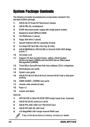
... power supply with single power module 4) Backplane board (BP6LS-AS35) 5) CD-ROM drive (1 piece) 6) floppy disk drive (1 piece) 7) special heatsink with fan assembly (2 sets) 8) hot swap IDE hard disk drive tray (6 units) 9) ASUS BBATA2U3, ATA133 IDE to Ultra160 SCSI HDD Bridge board x 1 10) AC power cord 11) Support CD that includes drivers, utilities, ASUS System Monitoring Agent (ASMA) with the ASUS Server Web-based Management (ASWM) 12) Trend Micro ServerProtect Anti-virus software CD for enterprises 13) Motherboard user guide 14) System user guide...
... power supply with single power module 4) Backplane board (BP6LS-AS35) 5) CD-ROM drive (1 piece) 6) floppy disk drive (1 piece) 7) special heatsink with fan assembly (2 sets) 8) hot swap IDE hard disk drive tray (6 units) 9) ASUS BBATA2U3, ATA133 IDE to Ultra160 SCSI HDD Bridge board x 1 10) AC power cord 11) Support CD that includes drivers, utilities, ASUS System Monitoring Agent (ASMA) with the ASUS Server Web-based Management (ASWM) 12) Trend Micro ServerProtect Anti-virus software CD for enterprises 13) Motherboard user guide 14) System user guide...
AP1710-I5 English Manual
Page 14
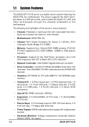
... power module. • Hardware Monitors: Voltage, temperature, Automatic System Restart (ASR), fan speed. 1-2 ASUS AP1710-I5 Two UltraDMA 100 IDE channels and one ATA66 IDE channel. • Graphics: ATI RAGE-XL PCI with 8MB PC-100 SDRAM video memory • Onboard IO: 1 X PS/2 mouse port, 1 X PS/2 keyboard slot, 1 X serial ports, 1 X 15-pin VGA port, 1 X floppy drive slot, 3 X IDE ports, 4 X USB ports, 1 X RJ-45 LAN port, 2 X 68-pin SCSI connectors • Special IO: IPMB connector, SM-Bus • Expansion: 4 X 64-bit/33Mhz 3V PCI slots...
... power module. • Hardware Monitors: Voltage, temperature, Automatic System Restart (ASR), fan speed. 1-2 ASUS AP1710-I5 Two UltraDMA 100 IDE channels and one ATA66 IDE channel. • Graphics: ATI RAGE-XL PCI with 8MB PC-100 SDRAM video memory • Onboard IO: 1 X PS/2 mouse port, 1 X PS/2 keyboard slot, 1 X serial ports, 1 X 15-pin VGA port, 1 X floppy drive slot, 3 X IDE ports, 4 X USB ports, 1 X RJ-45 LAN port, 2 X 68-pin SCSI connectors • Special IO: IPMB connector, SM-Bus • Expansion: 4 X 64-bit/33Mhz 3V PCI slots...
AP1710-I5 English Manual
Page 15
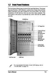
... LED display, refer to the hard disk drives. CD-ROM Drive 3.5" Floppy Drive 2 empty 5.25" bays Status LED Drive Activity LED Reset Button Power Button Power LED HDD Access LED Message LED 6 ATA 133 Hard Drive Swap Trays Front Door Lock 2 USB Ports For more detailed information of the server is protected by a door and lock for added security. 1.2 Front Panel Features The front panel allows easy access to "1.5 LED Table" on the front panel. The power and reset buttons, LED indicators, optical drive, floppy drive and two USB connectors...
... LED display, refer to the hard disk drives. CD-ROM Drive 3.5" Floppy Drive 2 empty 5.25" bays Status LED Drive Activity LED Reset Button Power Button Power LED HDD Access LED Message LED 6 ATA 133 Hard Drive Swap Trays Front Door Lock 2 USB Ports For more detailed information of the server is protected by a door and lock for added security. 1.2 Front Panel Features The front panel allows easy access to "1.5 LED Table" on the front panel. The power and reset buttons, LED indicators, optical drive, floppy drive and two USB connectors...
AP1710-I5 English Manual
Page 16
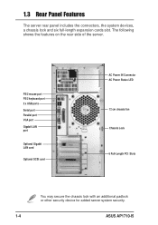
... port PS/2 keyboard port 2 x USB ports Serial port Parallel port VGA port Gigabit LAN port Optional Gigabit LAN card Optional SCSI card AC Power IN Connector AC Power Status LED 12 cm chassis fan Chassis Lock 6 Full-Length PCI Slots You may secure the chassis lock with an additional padlock or other security device for added server system security. 1-4 ASUS AP1710-I5 1.3 Rear Panel Features The server rear panel includes the connectors, the system devices, a chassis lock and six full-length expansion cards slot. The following shows the features on the rear...
... port PS/2 keyboard port 2 x USB ports Serial port Parallel port VGA port Gigabit LAN port Optional Gigabit LAN card Optional SCSI card AC Power IN Connector AC Power Status LED 12 cm chassis fan Chassis Lock 6 Full-Length PCI Slots You may secure the chassis lock with an additional padlock or other security device for added server system security. 1-4 ASUS AP1710-I5 1.3 Rear Panel Features The server rear panel includes the connectors, the system devices, a chassis lock and six full-length expansion cards slot. The following shows the features on the rear...
AP1710-I5 English Manual
Page 17
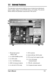
Chassis intrusion sensor User's Manual 1-5 CPU sockets 8. PRL-DL motherboard 12. The picture below shows the standard components of the server. 1 4 7 2 12 11 6 3 8 5 10 9 1. HDD hot swap modules 6. 4 x 64 bit 3V PCI slots 7. PCI Long Card support guide 10. 12 cm hot swap module blower 11. 1.4 Internal Features The standard components inside the server include the motherboard, power supply, floppy and CD-ROM drives, and cables. Redundant power supply cage 2. 4 x DDR DIMM sockets 3. 2 x IDE cable 4. 51/4" CD-ROM drive 5. Internal 68-pin SCSI cable 9.
Chassis intrusion sensor User's Manual 1-5 CPU sockets 8. PRL-DL motherboard 12. The picture below shows the standard components of the server. 1 4 7 2 12 11 6 3 8 5 10 9 1. HDD hot swap modules 6. 4 x 64 bit 3V PCI slots 7. PCI Long Card support guide 10. 12 cm hot swap module blower 11. 1.4 Internal Features The standard components inside the server include the motherboard, power supply, floppy and CD-ROM drives, and cables. Redundant power supply cage 2. 4 x DDR DIMM sockets 3. 2 x IDE cable 4. 51/4" CD-ROM drive 5. Internal 68-pin SCSI cable 9.
AP1710-I5 English Manual
Page 18
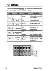
Icon 1 1 2 3 4 LED Display Description Green Drive Status LED Red Bridge board connected to SCSI backplane Bridge board failure Drive Activity LED Blinking HDD Read/Write data ON Power LED Blinking HDD Access OFF LED Blinking Message LED OFF Blinking System power ON Suspend Mode No activity Read/Write data in HDD Normal/No incoming event ASMS indicate HW monitor event 1 2 3 4 1-6 ASUS AP1710-I5 1.5 LED Table The following table describes the LED display found on the front panel and rear panel of the AP1710-I5 server system.
Icon 1 1 2 3 4 LED Display Description Green Drive Status LED Red Bridge board connected to SCSI backplane Bridge board failure Drive Activity LED Blinking HDD Read/Write data ON Power LED Blinking HDD Access OFF LED Blinking Message LED OFF Blinking System power ON Suspend Mode No activity Read/Write data in HDD Normal/No incoming event ASMS indicate HW monitor event 1 2 3 4 1-6 ASUS AP1710-I5 1.5 LED Table The following table describes the LED display found on the front panel and rear panel of the AP1710-I5 server system.
AP1710-I5 English Manual
Page 20
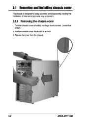
The side chassis cover is designed for about half an inch. 3. Release the cover from the chassis. 2-2 ASUS AP1710-I5 2.1 Removing and installing chassis cover The chassis is held by two large thumb screws. Loosen the screws. 2. Slide the chassis cover for easy assembly and disassembly, making the installation of internal components very convenient. 2.1.1 Removing the chassis cover 1.
The side chassis cover is designed for about half an inch. 3. Release the cover from the chassis. 2-2 ASUS AP1710-I5 2.1 Removing and installing chassis cover The chassis is held by two large thumb screws. Loosen the screws. 2. Slide the chassis cover for easy assembly and disassembly, making the installation of internal components very convenient. 2.1.1 Removing the chassis cover 1.
AP1710-I5 English Manual
Page 22
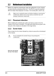
... the image below. 2.2.2 Screw holes Place screws into the holes indicated by circles to secure the motherboard to unplug the power cord before installing or removing the motherboard. Make sure to the chassis. Failure to do so may damage the motherboard. The edge with external ports goes to the rear part of the chassis 2-4 ASUS AP1710-I5 Do not overtighten the screws! 2.2 Motherboard installation Before you place it .
... the image below. 2.2.2 Screw holes Place screws into the holes indicated by circles to secure the motherboard to unplug the power cord before installing or removing the motherboard. Make sure to the chassis. Failure to do so may damage the motherboard. The edge with external ports goes to the rear part of the chassis 2-4 ASUS AP1710-I5 Do not overtighten the screws! 2.2 Motherboard installation Before you place it .
AP1710-I5 English Manual
Page 26
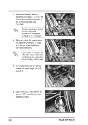
... fail to install two CPUs, repeat the same steps for the second CPU heatsink and fan assembly cable. 2-8 ASUS AP1710-I5 Use CPUFAN2 connector for CPU socket 2. 6. Make sure that the heatsink and fan assembly is in place and the fan power cable are connected properly. Don't forget to the fan connector on the motherboard labeled CPUFAN1. When the heatsink and fan assembly is stable in place, connect the fan cable to connect the CPU fan cable...
... fail to install two CPUs, repeat the same steps for the second CPU heatsink and fan assembly cable. 2-8 ASUS AP1710-I5 Use CPUFAN2 connector for CPU socket 2. 6. Make sure that the heatsink and fan assembly is in place and the fan power cable are connected properly. Don't forget to the fan connector on the motherboard labeled CPUFAN1. When the heatsink and fan assembly is stable in place, connect the fan cable to connect the CPU fan cable...
AP1710-I5 English Manual
Page 31
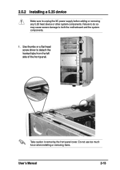
Take caution in removing the front panel cover. Failure to do so may cause severe damage to detach the hooked tabs from the left side of the front panel. Use thumbs or a flat-head screw driver to both the motherboard and the system components. 1. Do not use too much force when installing or removing items. User's Manual 2-13 2.5.2 Installing a 5.25 device Make sure to unplug the AC power supply before adding or removing any 5.25 fixed device or other system components.
Take caution in removing the front panel cover. Failure to do so may cause severe damage to detach the hooked tabs from the left side of the front panel. Use thumbs or a flat-head screw driver to both the motherboard and the system components. 1. Do not use too much force when installing or removing items. User's Manual 2-13 2.5.2 Installing a 5.25 device Make sure to unplug the AC power supply before adding or removing any 5.25 fixed device or other system components.
AP1710-I5 English Manual
Page 34
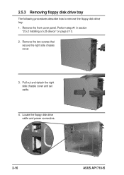
Remove the front cover panel. Remove the two screws that secure the right side chassis cover. 3. Locate the floppy disk drive cable and power connectors. 2-16 ASUS AP1710-I5 Perform step #1 in section "2.5.2 Installing a 5.25 device" on page 2-13. 2. Pull out and detach the right side chassis cover and set aside. 4. 2.5.3 Removing floppy disk drive tray The following procedures describe how to remove the floppy disk drive tray. 1.
Remove the front cover panel. Remove the two screws that secure the right side chassis cover. 3. Locate the floppy disk drive cable and power connectors. 2-16 ASUS AP1710-I5 Perform step #1 in section "2.5.2 Installing a 5.25 device" on page 2-13. 2. Pull out and detach the right side chassis cover and set aside. 4. 2.5.3 Removing floppy disk drive tray The following procedures describe how to remove the floppy disk drive tray. 1.
AP1710-I5 English Manual
Page 42
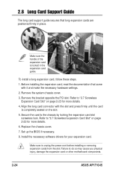
... the power cord before installing or removing expansion cards from the slot. Refer to "2.7 Screwless Expansion Card Slot" on the slot. 5. Failure to "2.7 Screwless Expansion Card Slot" on page 2-23 for your expansion card. 2.8 Long Card Support Guide The long card support guide secures that came with the slot and press firmly until the card is locked in place. Refer to do so may cause you physical injury, damage the expansion card or other motherboard components. 2-24 ASUS AP1710-I5 Remove...
... the power cord before installing or removing expansion cards from the slot. Refer to "2.7 Screwless Expansion Card Slot" on the slot. 5. Failure to "2.7 Screwless Expansion Card Slot" on page 2-23 for your expansion card. 2.8 Long Card Support Guide The long card support guide secures that came with the slot and press firmly until the card is locked in place. Refer to do so may cause you physical injury, damage the expansion card or other motherboard components. 2-24 ASUS AP1710-I5 Remove...
AP1710-I5 English Manual
Page 45
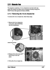
chassis fan pin-locks 2. User's Manual 2-27 2.11 Chassis Fan The chassis is cooled by a 12-cm chassis fan mounted at the rear panel.The chassis fan status can be monitored remotely through the ASUS® Server Management Software (ASMS). 2.11.1 Removing the 12-cm chassis fan To remove the 12-cm chassis fan, follow these steps. 1. Release all four (4) screws and push the pin to the rear panel. 3. Pull out the 12-cm chassis fan. Remove the 12-cm chassis fan 3-pin power cable (SYSFAN3) from the motherboard.
chassis fan pin-locks 2. User's Manual 2-27 2.11 Chassis Fan The chassis is cooled by a 12-cm chassis fan mounted at the rear panel.The chassis fan status can be monitored remotely through the ASUS® Server Management Software (ASMS). 2.11.1 Removing the 12-cm chassis fan To remove the 12-cm chassis fan, follow these steps. 1. Release all four (4) screws and push the pin to the rear panel. 3. Pull out the 12-cm chassis fan. Remove the 12-cm chassis fan 3-pin power cable (SYSFAN3) from the motherboard.
AP1710-I5 English Manual
Page 59
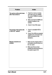
.... 2. Problem Action The system continuously beeps after it has VGA output. The message "Non-system disk or disk error" appears 1. Make sure that the DIMMs are properly installed and connected to the RJ-45 port on the backplane. Make sure that you installed the correct DIMMs the system supports. 2. Check if the HDDs are properly installed on 1. Check if a bootable HDD is connected to the SCSI connectors on the rear panel. 2. Check the memory modules...
.... 2. Problem Action The system continuously beeps after it has VGA output. The message "Non-system disk or disk error" appears 1. Make sure that the DIMMs are properly installed and connected to the RJ-45 port on the backplane. Make sure that you installed the correct DIMMs the system supports. 2. Check if the HDDs are properly installed on 1. Check if a bootable HDD is connected to the SCSI connectors on the rear panel. 2. Check the memory modules...


