Motherboard DIY Troubleshooting Guide
Page 3
Features Contents Notices v Safety information vi About this guide vii ASUS contact information viii A7V600 SE specifications summary ix Chapter 1: Product introduction 1.1 Welcome 1-2 1.2 Package contents 1-2 1.3 Special Features 1-3 1.3.1 Product highlights 1-3 1.3.2 Value-added solutions 1-5 1.4 Motherboard components 1-6 Core specifications 1-7 1.5 Motherboard...for this motherboard 1-16 1.10.3 AGP slot 1-16 1.10.4 WiFi slot 1-17 1.11 Jumpers 1-18 1.12 Connectors 1-20 Chapter 2: BIOS information 2.1 Managing and updating your BIOS 2-2 2.1.1 Using ASUS EZ Flash to update the...
Features Contents Notices v Safety information vi About this guide vii ASUS contact information viii A7V600 SE specifications summary ix Chapter 1: Product introduction 1.1 Welcome 1-2 1.2 Package contents 1-2 1.3 Special Features 1-3 1.3.1 Product highlights 1-3 1.3.2 Value-added solutions 1-5 1.4 Motherboard components 1-6 Core specifications 1-7 1.5 Motherboard...for this motherboard 1-16 1.10.3 AGP slot 1-16 1.10.4 WiFi slot 1-17 1.11 Jumpers 1-18 1.12 Connectors 1-20 Chapter 2: BIOS information 2.1 Managing and updating your BIOS 2-2 2.1.1 Using ASUS EZ Flash to update the...
Motherboard DIY Troubleshooting Guide
Page 4
Safeguards Contents 2.1.2 Using AFLASH to update the BIOS 2-4 2.1.3 Recovering the BIOS with CrashFree BIOS 2 ....... 2-7 2.2 BIOS Setup program 2-9 2.2.1 BIOS menu bar 2-9 2.2.2 Legend bar 2-10 2.3 Main Menu 2-11 2.3.1 Primary and Secondary ...the support CD 3-2 3.2.2 Drivers menu 3-3 3.2.3 Utilities menu 3-3 3.2.4 ASUS Contact Information 3-4 3.3 ASUS Instant Music Lite 3-5 3.4 RAID 0 / RAID 1 / RAID 0 + 1 Configurations 3-7 3.4.1 Install the Serial ATA (SATA) hard disks 3-8 3.4.2 Enter VIA® Tech RAID BIOS Utility 3-9 3.4.3 Create Array 3-10 3.4.4 Delete Array 3-13 3.4.5 ...
Safeguards Contents 2.1.2 Using AFLASH to update the BIOS 2-4 2.1.3 Recovering the BIOS with CrashFree BIOS 2 ....... 2-7 2.2 BIOS Setup program 2-9 2.2.1 BIOS menu bar 2-9 2.2.2 Legend bar 2-10 2.3 Main Menu 2-11 2.3.1 Primary and Secondary ...the support CD 3-2 3.2.2 Drivers menu 3-3 3.2.3 Utilities menu 3-3 3.2.4 ASUS Contact Information 3-4 3.3 ASUS Instant Music Lite 3-5 3.4 RAID 0 / RAID 1 / RAID 0 + 1 Configurations 3-7 3.4.1 Install the Serial ATA (SATA) hard disks 3-8 3.4.2 Enter VIA® Tech RAID BIOS Utility 3-9 3.4.3 Create Array 3-10 3.4.4 Delete Array 3-13 3.4.5 ...

Motherboard DIY Troubleshooting Guide
Page 9
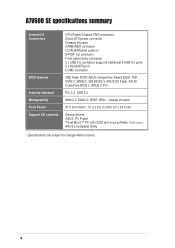
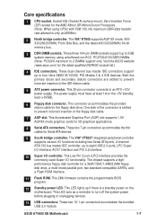
A7V600 SE specifications summary CPU Chipset Front Side Bus (FSB) Memory Expansion slots Storage Audio AI Net Special Features Overclocking Features Back Panel I/O Socket A for AMD ...AD1980 SoundMAX 6-channel CODEC S/PDIF out interface Marvell® 88E8001 Gigabit LAN controller Virtual Cable Tester (VCT) Technology support ASUS EZ Flash Power Loss Restart ASUS C.O.P. (CPU Overheating Protection) ASUS CrashFree BIOS 2 ASUS Instant Music Lite ASUS JumperFree ASUS C.P.R. (CPU Parameter Recall) CPU, Memory, and AGP Voltage adjustable SFS (Stepless Frequency Selection) from 100Mhz up to 250MHz...
A7V600 SE specifications summary CPU Chipset Front Side Bus (FSB) Memory Expansion slots Storage Audio AI Net Special Features Overclocking Features Back Panel I/O Socket A for AMD ...AD1980 SoundMAX 6-channel CODEC S/PDIF out interface Marvell® 88E8001 Gigabit LAN controller Virtual Cable Tester (VCT) Technology support ASUS EZ Flash Power Loss Restart ASUS C.O.P. (CPU Overheating Protection) ASUS CrashFree BIOS 2 ASUS Instant Music Lite ASUS JumperFree ASUS C.P.R. (CPU Parameter Recall) CPU, Memory, and AGP Voltage adjustable SFS (Stepless Frequency Selection) from 100Mhz up to 250MHz...
Motherboard DIY Troubleshooting Guide
Page 10
... Front panel audio connector 2 x USB 2.0 connector supports additional 4 USB 2.0 ports 2 x Serial ATA port COM2 connector 2Mb Flash ROM, ASUS Jumperfree, Award BIOS, PnP, DMI2.0, WfM2.0, SM BIOS2.3, ASUS EZ Flash, ASUS CrashFree BIOS 2, ASUS C.P.R. x A7V600 SE specifications summary Internal I/O Connectors BIOS features Industry standard Manageability Form Factor Support CD contents CPU/Power/Chassis FAN connectors 20 pin ATX power...
... Front panel audio connector 2 x USB 2.0 connector supports additional 4 USB 2.0 ports 2 x Serial ATA port COM2 connector 2Mb Flash ROM, ASUS Jumperfree, Award BIOS, PnP, DMI2.0, WfM2.0, SM BIOS2.3, ASUS EZ Flash, ASUS CrashFree BIOS 2, ASUS C.P.R. x A7V600 SE specifications summary Internal I/O Connectors BIOS features Industry standard Manageability Form Factor Support CD contents CPU/Power/Chassis FAN connectors 20 pin ATX power...
Motherboard DIY Troubleshooting Guide
Page 14
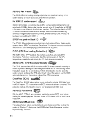
S/PDIF out port on Back I/O The A7V600 SE provides convenient connectivity to Windows™. Experience 5.1-channel surround sound and enhanced 3D audio while playing your favorite DVDs or games. feature of devices such ... ROM chip. If the CPU temperature exceeds the set criteria, the PC shuts down automatically. eliminates the need to restore the original BIOS data from a floppy disk. ASUS Q-Fan feature The ASUS Q-Fan technology smartly adjusts the fan speeds according to the system loading to ensure quiet, cool, and efficient operation. 8 x USB 2.0 ports...
S/PDIF out port on Back I/O The A7V600 SE provides convenient connectivity to Windows™. Experience 5.1-channel surround sound and enhanced 3D audio while playing your favorite DVDs or games. feature of devices such ... ROM chip. If the CPU temperature exceeds the set criteria, the PC shuts down automatically. eliminates the need to restore the original BIOS data from a floppy disk. ASUS Q-Fan feature The ASUS Q-Fan technology smartly adjusts the fan speeds according to the system loading to ensure quiet, cool, and efficient operation. 8 x USB 2.0 ports...
Motherboard DIY Troubleshooting Guide
Page 15
... detection The motherboard supports chassis intrusion monitoring. ASUS A7V600 SE Motherboard 1-5 Connect to the Internet then to the ASUS FTP site nearest you to update the motherboard BIOS through a user-friendly interface. A chassis intrusion event is retained in BIOS using the ASUS JumperFree™ solution • C.P.R. (CPU... Stepless Frequency Selection (SFS) for fine-tuning system bus frequency from 100MHz up to obtain the latest BIOS version for your motherboard. ASUS update This utility allows you to 250MHz at 1MHz increments Temperature, fan, and voltage monitoring The CPU ...
... detection The motherboard supports chassis intrusion monitoring. ASUS A7V600 SE Motherboard 1-5 Connect to the Internet then to the ASUS FTP site nearest you to update the motherboard BIOS through a user-friendly interface. A chassis intrusion event is retained in BIOS using the ASUS JumperFree™ solution • C.P.R. (CPU... Stepless Frequency Selection (SFS) for fine-tuning system bus frequency from 100MHz up to obtain the latest BIOS version for your motherboard. ASUS update This utility allows you to 250MHz at 1MHz increments Temperature, fan, and voltage monitoring The CPU ...
Motherboard DIY Troubleshooting Guide
Page 17
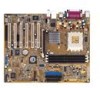
... connector is a standby power on the +5V standby lead (+5VSB). 6 Floppy disk connector. This 2Mb firmware contains the programmable BIOS program. 12 Standby power LED. This LED lights up to eight USB 2.0 ports, LPC Super I/O interface, AC'97 interface and...Front Side Bus, and the latest 400/333/266MHz 64-bit memory bus. 3 DDR DIMM sockets. Visit the ASUS website (www.asus.com) for a 360K/720K/1.44M/2.88M floppy disk drive, a multi-mode parallel port, two standard compatible ... Low Pin Count (LPC) interface provides the commonly used Super I /O controller. ASUS A7V600 SE Motherboard 1-7
... connector is a standby power on the +5V standby lead (+5VSB). 6 Floppy disk connector. This 2Mb firmware contains the programmable BIOS program. 12 Standby power LED. This LED lights up to eight USB 2.0 ports, LPC Super I/O interface, AC'97 interface and...Front Side Bus, and the latest 400/333/266MHz 64-bit memory bus. 3 DDR DIMM sockets. Visit the ASUS website (www.asus.com) for a 360K/720K/1.44M/2.88M floppy disk drive, a multi-mode parallel port, two standard compatible ... Low Pin Count (LPC) interface provides the commonly used Super I /O controller. ASUS A7V600 SE Motherboard 1-7

Motherboard DIY Troubleshooting Guide
Page 25
Turn on the system and change the necessary BIOS settings, if any. 2. 1.10 Expansion slots The A7V600 SE motherboard has six (6) expansion PCI slots and one (1) AGP 8X slot. The following sub-sections describe the slots and the expansion cards ... 1.10.1 Configuring an expansion card After physically installing the expansion card, configure the card by adjusting the software settings. 1. Refer to the card. ASUS A7V600 SE Motherboard 1-15 Assign an IRQ to the tables below. 3. Install the software drivers for the expansion card. 1.10.2 Standard Interrupt Assignments IRQ Priority ...
Turn on the system and change the necessary BIOS settings, if any. 2. 1.10 Expansion slots The A7V600 SE motherboard has six (6) expansion PCI slots and one (1) AGP 8X slot. The following sub-sections describe the slots and the expansion cards ... 1.10.1 Configuring an expansion card After physically installing the expansion card, configure the card by adjusting the software settings. 1. Refer to the card. ASUS A7V600 SE Motherboard 1-15 Assign an IRQ to the tables below. 3. Install the software drivers for the expansion card. 1.10.2 Standard Interrupt Assignments IRQ Priority ...
Motherboard DIY Troubleshooting Guide
Page 28
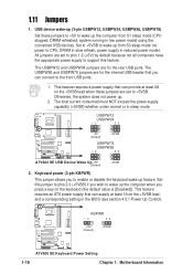
...computer when you to +5VSB. The total current consumed must NOT exceed the power supply capability (+5VSB) whether under normal or in the BIOS (see section 4.5.1 Power Up Control). Keyboard power (3-pin KBPWR) This jumper allows you press a key on the keyboard (the default ...system does not power up from S1 sleep mode (CPU stopped, DRAM refreshed, system running in reduced power mode). A7V600 SE KBPWR 12 23 +5V (Default) +5VSB ® A7V600 SE Keyboard Power Setting 1-18 Chapter 1: Motherboard Information This feature requires a power supply that you can supply at least ...
...computer when you to +5VSB. The total current consumed must NOT exceed the power supply capability (+5VSB) whether under normal or in the BIOS (see section 4.5.1 Power Up Control). Keyboard power (3-pin KBPWR) This jumper allows you press a key on the keyboard (the default ...system does not power up from S1 sleep mode (CPU stopped, DRAM refreshed, system running in reduced power mode). A7V600 SE KBPWR 12 23 +5V (Default) +5VSB ® A7V600 SE Keyboard Power Setting 1-18 Chapter 1: Motherboard Information This feature requires a power supply that you can supply at least ...
Motherboard DIY Troubleshooting Guide
Page 29
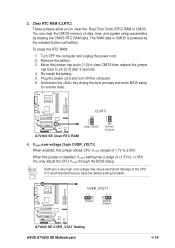
...seconds. 4. When this jumper allows CPU VCORE ranges of 1.7V to a very high core voltage may adjust the CPU VCORE through the BIOS Setup. Setting to 2.05V. Remove the battery. 3. It is disabled, VCORE setting has a range of date, time, and system ... the CMOS RTC RAM data. Plug the power cord and turn ON the computer. 6. A7V600 SE OVER_VOLT1 12 23 Enable Disable (Default) ® A7V600 SE OVER_VOLT Setting ASUS A7V600 SE Motherboard 1-19 The RAM data in CMOS. A7V600 SE ® A7V600 SE Clear RTC RAM CLRTC 2 1 Clear CMOS 3 2 Normal (Default) 4. Re-install ...
...seconds. 4. When this jumper allows CPU VCORE ranges of 1.7V to a very high core voltage may adjust the CPU VCORE through the BIOS Setup. Setting to 2.05V. Remove the battery. 3. It is disabled, VCORE setting has a range of date, time, and system ... the CMOS RTC RAM data. Plug the power cord and turn ON the computer. 6. A7V600 SE OVER_VOLT1 12 23 Enable Disable (Default) ® A7V600 SE OVER_VOLT Setting ASUS A7V600 SE Motherboard 1-19 The RAM data in CMOS. A7V600 SE ® A7V600 SE Clear RTC RAM CLRTC 2 1 Clear CMOS 3 2 Normal (Default) 4. Re-install ...
Motherboard DIY Troubleshooting Guide
Page 30
...cables. 2. If you connect non-UltraDMA/133/100/66 devices to the UltraDMA/133/100/66 master device. A7V600 SE NOTE: Orient the red markings (usually zigzag) on the UltraDMA/133/100/66 cable is intentional. It is...on the UltraDMA cable connector. Refer to be both master devices with two ribbon cables - PRI_IDE SEC_IDE ® A7V600 SE IDE Connectors PIN 1 PIN 1 For UltraDMA/133/100/66 IDE devices, use an 80-conductor IDE cable. ...the motherboard package also supports UltraDMA/133/100. 1-20 Chapter 1: Motherboard Information BIOS supports specific device bootup.
...cables. 2. If you connect non-UltraDMA/133/100/66 devices to the UltraDMA/133/100/66 master device. A7V600 SE NOTE: Orient the red markings (usually zigzag) on the UltraDMA/133/100/66 cable is intentional. It is...on the UltraDMA cable connector. Refer to be both master devices with two ribbon cables - PRI_IDE SEC_IDE ® A7V600 SE IDE Connectors PIN 1 PIN 1 For UltraDMA/133/100/66 IDE devices, use an 80-conductor IDE cable. ...the motherboard package also supports UltraDMA/133/100. 1-20 Chapter 1: Motherboard Information BIOS supports specific device bootup.
Motherboard DIY Troubleshooting Guide
Page 37
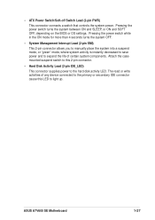
... the hard disk activity LED. Pressing the power switch turns the system between ON and SLEEP, or ON and SOFT OFF, depending on the BIOS or OS settings. ASUS A7V600 SE Motherboard 1-27 • ATX Power Switch/Soft-off Switch Lead (2-pin PWR) This connector connects a switch that controls the system power. The read...
... the hard disk activity LED. Pressing the power switch turns the system between ON and SLEEP, or ON and SOFT OFF, depending on the BIOS or OS settings. ASUS A7V600 SE Motherboard 1-27 • ATX Power Switch/Soft-off Switch Lead (2-pin PWR) This connector connects a switch that controls the system power. The read...
Motherboard DIY Troubleshooting Guide
Page 39
Chapter 2 This chapter tells how to change the system settings through the BIOS setup menus. Detailed descriptions of the BIOS parameters are also provided. BIOS Information ASUS A7V600 SE Motherboard 2-1
Chapter 2 This chapter tells how to change the system settings through the BIOS setup menus. Detailed descriptions of the BIOS parameters are also provided. BIOS Information ASUS A7V600 SE Motherboard 2-1
Motherboard DIY Troubleshooting Guide
Page 40
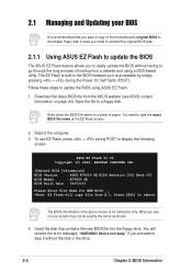
.... 2.1 Managing and Updating your screen may not be exactly the same as shown. 4. Reboot the computer. 3. ASUS EZ Flash V1.00 Copyright (C) 2002, ASUSTeK COMPUTER INC. [Onboard BIOS Information] BIOS Version : ASUS A7V600 SE BIOS Revision 1001 Beta 003 BIOS Model : A7V600 SE BIOS Built Date : 06/03/03 Please Enter File Name for reference only. Insert the disk that you...
.... 2.1 Managing and Updating your screen may not be exactly the same as shown. 4. Reboot the computer. 3. ASUS EZ Flash V1.00 Copyright (C) 2002, ASUSTeK COMPUTER INC. [Onboard BIOS Information] BIOS Version : ASUS A7V600 SE BIOS Revision 1001 Beta 003 BIOS Model : A7V600 SE BIOS Built Date : 06/03/03 Please Enter File Name for reference only. Insert the disk that you...
Motherboard DIY Troubleshooting Guide
Page 41
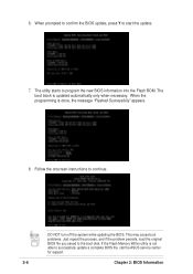
... exactly the same as shown. At the query prompt, type Y to reboot" appears. Flash Memory: SST 49LF004 1. Press . 6. Update Main BIOS area 2. When the update process is for both items to update the BIOS (Y/N)? _ 7. Update Boot Block area (Y/N)? _ (Y/N)? _ DO NOT shutdown or reset the system while updating the BIOS boot block area! ASUS A7V600 SE Motherboard 2-3 5.
... exactly the same as shown. At the query prompt, type Y to reboot" appears. Flash Memory: SST 49LF004 1. Press . 6. Update Main BIOS area 2. When the update process is for both items to update the BIOS (Y/N)? _ 7. Update Boot Block area (Y/N)? _ (Y/N)? _ DO NOT shutdown or reset the system while updating the BIOS boot block area! ASUS A7V600 SE Motherboard 2-3 5.
Motherboard DIY Troubleshooting Guide
Page 42
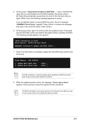
...create a bootable system disk. Type COPY D:\AFLASH\AFLASH.EXE A:\ (assuming D is a Flash Memory Writer utility that updates the BIOS by the Flash Memory Writer utility. 2-4 Chapter 2: BIOS Information Reboot the computer from the hard drive. It does not work with certain memory drivers that you reboot using a floppy ... "unknown" appears after Flash Memory:, the memory chip is either not programmable or is recommended that may be programmed by uploading a new BIOS file to the programmable flash ROM on the upper left-hand corner of your CD-ROM drive) to copy AFLASH.EXE to the boot ...
...create a bootable system disk. Type COPY D:\AFLASH\AFLASH.EXE A:\ (assuming D is a Flash Memory Writer utility that updates the BIOS by the Flash Memory Writer utility. 2-4 Chapter 2: BIOS Information Reboot the computer from the hard drive. It does not work with certain memory drivers that you reboot using a floppy ... "unknown" appears after Flash Memory:, the memory chip is either not programmable or is recommended that may be programmed by uploading a new BIOS file to the programmable flash ROM on the upper left-hand corner of your CD-ROM drive) to copy AFLASH.EXE to the boot ...
Motherboard DIY Troubleshooting Guide
Page 43
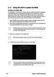
... the Main Menu, type 2 then press . Updating the BIOS Update the BIOS only if you created earlier. 2. At the "A:\" prompt, type AFLASH and then press . 4. ASUS A7V600 SE Motherboard 2-5 The Save Current BIOS To File screen appears. 6. Download an updated ASUS BIOS file from the Internet (WWW or FTP) (see ASUS CONTACT INFORMATION on page x for details) and save...
... the Main Menu, type 2 then press . Updating the BIOS Update the BIOS only if you created earlier. 2. At the "A:\" prompt, type AFLASH and then press . 4. ASUS A7V600 SE Motherboard 2-5 The Save Current BIOS To File screen appears. 6. Download an updated ASUS BIOS file from the Internet (WWW or FTP) (see ASUS CONTACT INFORMATION on page x for details) and save...
Motherboard DIY Troubleshooting Guide
Page 44
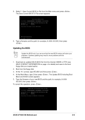
... the programming is updated automatically only when necessary. The utility starts to start the update. 7. DO NOT turn off the system while updating the BIOS. The boot block is done, the message "Flashed Successfully" appears. 8. This may cause boot problems. Just repeat the process, and if the... problem persists, load the original BIOS file you saved to continue. Follow the onscreen instructions to the boot disk. If the Flash Memory Writer utility is not able to successfully...
... the programming is updated automatically only when necessary. The utility starts to start the update. 7. DO NOT turn off the system while updating the BIOS. The boot block is done, the message "Flashed Successfully" appears. 8. This may cause boot problems. Just repeat the process, and if the... problem persists, load the original BIOS file you saved to continue. Follow the onscreen instructions to the boot disk. If the Flash Memory Writer utility is not able to successfully...
Motherboard DIY Troubleshooting Guide
Page 45
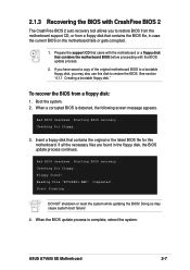
... from a floppy disk: 1. Start flashing... To recover the BIOS from a floppy disk that contains the motherboard BIOS before proceeding with CrashFree BIOS 2 The CrashFree BIOS 2 auto recovery tool allows you may cause system boot failure! 4. See section "4.1.1 Creating a bootable floppy disk." Bad BIOS checksum. Starting BIOS recovery... ASUS A7V600 SE Motherboard 2-7 Reading file "A7V6SE01.AWD". Completed. Doing so may...
... from a floppy disk: 1. Start flashing... To recover the BIOS from a floppy disk that contains the motherboard BIOS before proceeding with CrashFree BIOS 2 The CrashFree BIOS 2 auto recovery tool allows you may cause system boot failure! 4. See section "4.1.1 Creating a bootable floppy disk." Bad BIOS checksum. Starting BIOS recovery... ASUS A7V600 SE Motherboard 2-7 Reading file "A7V6SE01.AWD". Completed. Doing so may...
Motherboard DIY Troubleshooting Guide
Page 46
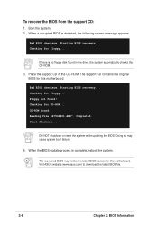
...BIOS recovery... The support CD contains the original BIOS for this motherboard. Floppy not found . Completed. Doing so may not be the latest BIOS version for CD-ROM... When a corrupted BIOS is complete, reboot the system. If there is no floppy disk found in the CD-ROM. Starting BIOS... recovery... Start flashing... Bad BIOS checksum. When the BIOS update process is detected, the following... reset the system while updating the BIOS! The recovered BIOS may cause system boot failure! 4. To recover the BIOS from the support CD: 1. Place...
...BIOS recovery... The support CD contains the original BIOS for this motherboard. Floppy not found . Completed. Doing so may not be the latest BIOS version for CD-ROM... When a corrupted BIOS is complete, reboot the system. If there is no floppy disk found in the CD-ROM. Starting BIOS... recovery... Start flashing... Bad BIOS checksum. When the BIOS update process is detected, the following... reset the system while updating the BIOS! The recovered BIOS may cause system boot failure! 4. To recover the BIOS from the support CD: 1. Place...


