Motherboard DIY Troubleshooting Guide
Page 14
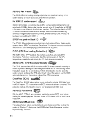
... Flash, you to buy a replacement ROM chip. S/PDIF out port on Back I/O The A7V600 SE provides convenient connectivity to prolong the life of the ASUS motherboard BIOS allows automatic resetting to the BIOS previous settings in case when the BIOS codes and data are corrupted. C.O.P. (CPU Overheating Protection): With AMD® Athlon XP™ installed, the motherboard...
... Flash, you to buy a replacement ROM chip. S/PDIF out port on Back I/O The A7V600 SE provides convenient connectivity to prolong the life of the ASUS motherboard BIOS allows automatic resetting to the BIOS previous settings in case when the BIOS codes and data are corrupted. C.O.P. (CPU Overheating Protection): With AMD® Athlon XP™ installed, the motherboard...

Motherboard DIY Troubleshooting Guide
Page 25
...BIOS settings, if any. 2. The following sub-sections describe the slots and the expansion cards that they support. 1.10.1 Configuring an expansion card After physically installing the expansion card, configure the card by adjusting the software settings. 1. Assign an IRQ to the tables below. 3. Refer to the card. ASUS A7V600 SE... Motherboard 1-15 1.10 Expansion slots The A7V600 SE motherboard has six (6) expansion PCI slots and one...
...BIOS settings, if any. 2. The following sub-sections describe the slots and the expansion cards that they support. 1.10.1 Configuring an expansion card After physically installing the expansion card, configure the card by adjusting the software settings. 1. Assign an IRQ to the tables below. 3. Refer to the card. ASUS A7V600 SE... Motherboard 1-15 1.10 Expansion slots The A7V600 SE motherboard has six (6) expansion PCI slots and one...
Motherboard DIY Troubleshooting Guide
Page 28
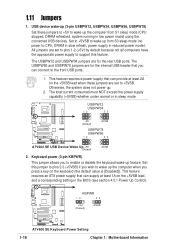
...Otherwise, the system does not power up (3-pin USBPW12, USBPW34, USBPW56, USBPW78) Set these jumpers are set to +5VSB. A7V600 SE KBPWR 12 23 +5V (Default) +5VSB ® A7V600 SE Keyboard Power Setting 1-18 Chapter 1: Motherboard Information Set to +5VSB to wake up feature. This feature requires a power supply that ... front USB ports. 1. The total current consumed must NOT exceed the power supply capability (+5VSB) whether under normal or in the BIOS (see section 4.5.1 Power Up Control). 1.11 Jumpers 1. USB device wake-up . 2. Keyboard power (3-pin KBPWR) This jumper ...
...Otherwise, the system does not power up (3-pin USBPW12, USBPW34, USBPW56, USBPW78) Set these jumpers are set to +5VSB. A7V600 SE KBPWR 12 23 +5V (Default) +5VSB ® A7V600 SE Keyboard Power Setting 1-18 Chapter 1: Motherboard Information Set to +5VSB to wake up feature. This feature requires a power supply that ... front USB ports. 1. The total current consumed must NOT exceed the power supply capability (+5VSB) whether under normal or in the BIOS (see section 4.5.1 Power Up Control). 1.11 Jumpers 1. USB device wake-up . 2. Keyboard power (3-pin KBPWR) This jumper ...
Motherboard DIY Troubleshooting Guide
Page 29
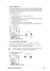
...pin [1-2] to clear CMOS then replace the jumper cap back to +1.85V. A7V600 SE ® A7V600 SE Clear RTC RAM CLRTC 2 1 Clear CMOS 3 2 Normal (Default) 4. A7V600 SE OVER_VOLT1 12 23 Enable Disable (Default) ® A7V600 SE OVER_VOLT Setting ASUS A7V600 SE Motherboard 1-19 You can clear the CMOS memory of date, time, and...clear the Real Time Clock (RTC) RAM in CMOS is recommended that you to the CPU. Setting to a very high core voltage may adjust the CPU VCORE through the BIOS Setup. Turn OFF the computer and unplug the power cord. 2. Re-install the battery. 5....
...pin [1-2] to clear CMOS then replace the jumper cap back to +1.85V. A7V600 SE ® A7V600 SE Clear RTC RAM CLRTC 2 1 Clear CMOS 3 2 Normal (Default) 4. A7V600 SE OVER_VOLT1 12 23 Enable Disable (Default) ® A7V600 SE OVER_VOLT Setting ASUS A7V600 SE Motherboard 1-19 You can clear the CMOS memory of date, time, and...clear the Real Time Clock (RTC) RAM in CMOS is recommended that you to the CPU. Setting to a very high core voltage may adjust the CPU VCORE through the BIOS Setup. Turn OFF the computer and unplug the power cord. 2. Re-install the battery. 5....
Motherboard DIY Troubleshooting Guide
Page 30
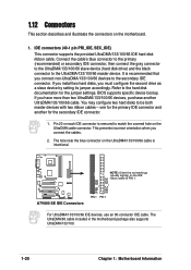
... UltraDMA/133/100/66 IDE hard disk ribbon cable. BIOS supports specific device bootup. You may configure two hard disks to the UltraDMA/133/100/66 master device. one for the primary IDE connector and another UltraDMA/133/100/66 cable. A7V600 SE NOTE: Orient the red markings (usually zigzag) on... connector on each IDE connector is recommended that you have more than two UltraDMA/133/100/66 devices, purchase another for the jumper settings. PRI_IDE SEC_IDE ® A7V600 SE IDE Connectors PIN 1 PIN 1 For UltraDMA/133/100/66 IDE devices, use an 80-conductor IDE cable.
... UltraDMA/133/100/66 IDE hard disk ribbon cable. BIOS supports specific device bootup. You may configure two hard disks to the UltraDMA/133/100/66 master device. one for the primary IDE connector and another UltraDMA/133/100/66 cable. A7V600 SE NOTE: Orient the red markings (usually zigzag) on... connector on each IDE connector is recommended that you have more than two UltraDMA/133/100/66 devices, purchase another for the jumper settings. PRI_IDE SEC_IDE ® A7V600 SE IDE Connectors PIN 1 PIN 1 For UltraDMA/133/100/66 IDE devices, use an 80-conductor IDE cable.
Motherboard DIY Troubleshooting Guide
Page 37
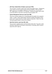
... that controls the system power. Pressing the power switch turns the system between ON and SLEEP, or ON and SOFT OFF, depending on the BIOS or OS settings. Pressing the power switch while in the ON mode for more than 4 seconds turns the system OFF. • System Management Interrupt Lead (2-pin SMI... to the primary or secondary IDE connector cause this 2-pin connector. • Hard Disk Activity Lead (2-pin IDE_LED) This connector supplies power to light up. ASUS A7V600 SE Motherboard 1-27
... that controls the system power. Pressing the power switch turns the system between ON and SLEEP, or ON and SOFT OFF, depending on the BIOS or OS settings. Pressing the power switch while in the ON mode for more than 4 seconds turns the system OFF. • System Management Interrupt Lead (2-pin SMI... to the primary or secondary IDE connector cause this 2-pin connector. • Hard Disk Activity Lead (2-pin IDE_LED) This connector supplies power to light up. ASUS A7V600 SE Motherboard 1-27
Motherboard DIY Troubleshooting Guide
Page 39
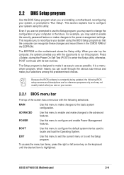
Detailed descriptions of the BIOS parameters are also provided. BIOS Information ASUS A7V600 SE Motherboard 2-1 Chapter 2 This chapter tells how to change the system settings through the BIOS setup menus.
Detailed descriptions of the BIOS parameters are also provided. BIOS Information ASUS A7V600 SE Motherboard 2-1 Chapter 2 This chapter tells how to change the system settings through the BIOS setup menus.
Motherboard DIY Troubleshooting Guide
Page 47
...see on your screen. 2.2.1 BIOS menu bar The top of .... It is highlighted. Because the BIOS software is designed to make changes to the basic system configuration. ASUS A7V600 SE Motherboard 2-9 The Setup program is... the current menu or to configure your system using the BIOS Setup program so that the computer can scroll through the ... RAM of the screen has a menu bar with the following BIOS setup screens and descriptions are for reference purposes only, and may...them in the future. 2.2 BIOS Setup program Use the BIOS Setup program when you are installing a motherboard, reconfiguring ...
...see on your screen. 2.2.1 BIOS menu bar The top of .... It is highlighted. Because the BIOS software is designed to make changes to the basic system configuration. ASUS A7V600 SE Motherboard 2-9 The Setup program is... the current menu or to configure your system using the BIOS Setup program so that the computer can scroll through the ... RAM of the screen has a menu bar with the following BIOS setup screens and descriptions are for reference purposes only, and may...them in the future. 2.2 BIOS Setup program Use the BIOS Setup program when you are installing a motherboard, reconfiguring ...
Motherboard DIY Troubleshooting Guide
Page 50
.... This password allows full access to the BIOS during system startup. Forgot the password? If you forget your BIOS" on a bootable floppy disk before setting passwords. Re-install the battery after about passwords The BIOS Setup program allows you to set to erase the CMOS RAM, unplug the ... RAM. You will need to [Disabled]. A note about 2 seconds, then power up to upload the BIOS file in case you did not set a Supervisor password, anyone can access the BIOS Setup program. The same dialog box as opposed to specify passwords in the future. The RAM data containing...
.... This password allows full access to the BIOS during system startup. Forgot the password? If you forget your BIOS" on a bootable floppy disk before setting passwords. Re-install the battery after about passwords The BIOS Setup program allows you to set to erase the CMOS RAM, unplug the ... RAM. You will need to [Disabled]. A note about 2 seconds, then power up to upload the BIOS file in case you did not set a Supervisor password, anyone can access the BIOS Setup program. The same dialog box as opposed to specify passwords in the future. The RAM data containing...
Motherboard DIY Troubleshooting Guide
Page 52
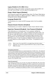
.... Refer to the drive documentation to determine the correct value. Maximum LBA Capacity This field shows the drive's maximum LBA capacity as calculated by the BIOS based on this field. for the hard disk drive that LBA Mode is installed or if you configured. Head This field configures the number of... in this sub-menu, press the key to return to the Main menu. Note that you are : [CD-ROM] - To make changes to this field, set the Type field to [User Type HDD] and the Translation Method field to [Manual]. CHS Capacity This field shows the drive's maximum CHS capacity as...
.... Refer to the drive documentation to determine the correct value. Maximum LBA Capacity This field shows the drive's maximum LBA capacity as calculated by the BIOS based on this field. for the hard disk drive that LBA Mode is installed or if you configured. Head This field configures the number of... in this sub-menu, press the key to return to the Main menu. Note that you are : [CD-ROM] - To make changes to this field, set the Type field to [User Type HDD] and the Translation Method field to [Manual]. CHS Capacity This field shows the drive's maximum CHS capacity as...
Motherboard DIY Troubleshooting Guide
Page 54
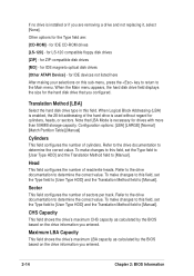
...frequency. CPU External Frequency (MHz) This feature tells the clock generator what frequency to send to [Auto]. 2-16 Chapter 2: BIOS Information Configuration options: [Auto] [266] [333] [400]. The bus frequency (external frequency) multiplied by the bus multiple equals the CPU ...speed. CPU VCore Setting [Auto] The [Manual] setting allows you keep the default setting [Auto] to allow the system to automatically determine the appropriate CPU core voltage. It is recommended that you ...
...frequency. CPU External Frequency (MHz) This feature tells the clock generator what frequency to send to [Auto]. 2-16 Chapter 2: BIOS Information Configuration options: [Auto] [266] [333] [400]. The bus frequency (external frequency) multiplied by the bus multiple equals the CPU ...speed. CPU VCore Setting [Auto] The [Manual] setting allows you keep the default setting [Auto] to allow the system to automatically determine the appropriate CPU core voltage. It is recommended that you ...
Motherboard DIY Troubleshooting Guide
Page 55
... legacy mode is enabled. Configuration options: [Disabled] [Enabled] ASUS A7V600 SE Motherboard 2-17 If a mouse is detected at startup. Otherwise, IRQ12 can only be used for expansion cards. Configuration options: [Disabled] [Enabled] PS/2 Mouse Function Control [Auto] The default setting [Auto] allows the system to [Enabled], BIOS reserves IRQ12, whether or not a PS/2 mouse is...
... legacy mode is enabled. Configuration options: [Disabled] [Enabled] ASUS A7V600 SE Motherboard 2-17 If a mouse is detected at startup. Otherwise, IRQ12 can only be used for expansion cards. Configuration options: [Disabled] [Enabled] PS/2 Mouse Function Control [Auto] The default setting [Auto] allows the system to [Enabled], BIOS reserves IRQ12, whether or not a PS/2 mouse is...

Motherboard DIY Troubleshooting Guide
Page 56
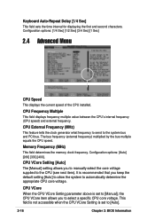
... stores critical information about the module, such as memory type, size, speed, voltage interface, and module banks. The default setting is automatically disabled. Configuration options: [1.5T] [2T] [2.5T] SDRAM RAS to [User Defined]. Instant Music CD ROM Allows...for items 2-5, depending on the memory modules that you wish to select the CD-ROM drive that you set the optimal timings for the Instant Music CD playback. The EEPROM on SDRAM SPD) This item controls the ...SPD (Serial Presence Detect) device. Configuration options: [5T] [4T] [3T] [2T]. 2-18 Chapter 2: BIOS Information
... stores critical information about the module, such as memory type, size, speed, voltage interface, and module banks. The default setting is automatically disabled. Configuration options: [1.5T] [2T] [2.5T] SDRAM RAS to [User Defined]. Instant Music CD ROM Allows...for items 2-5, depending on the memory modules that you wish to select the CD-ROM drive that you set the optimal timings for the Instant Music CD playback. The EEPROM on SDRAM SPD) This item controls the ...SPD (Serial Presence Detect) device. Configuration options: [5T] [4T] [3T] [2T]. 2-18 Chapter 2: BIOS Information
Motherboard DIY Troubleshooting Guide
Page 58
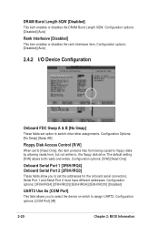
... the DRAM Burst Length 8QW. The default setting [R/W] allows both reads and writes. Configuration options: [COM Port] [IR] 2-20 Chapter 2: BIOS Information Configuration options: [Disabled] [Auto] 2.4.2 I/O Device Configuration Onboard FDC Swap A & B [No Swap] These fields set the addresses for the onboard serial connectors. ...[Disabled] UART2 Use As [COM Port] This field allows you to set option to , the floppy disk drive. Configuration Options: [No Swap] [Swap AB] Floppy Disk Access Control [R/W] When set to [Read Only], this item protects files from being copied to floppy ...
... the DRAM Burst Length 8QW. The default setting [R/W] allows both reads and writes. Configuration options: [COM Port] [IR] 2-20 Chapter 2: BIOS Information Configuration options: [Disabled] [Auto] 2.4.2 I/O Device Configuration Onboard FDC Swap A & B [No Swap] These fields set the addresses for the onboard serial connectors. ...[Disabled] UART2 Use As [COM Port] This field allows you to set option to , the floppy disk drive. Configuration Options: [No Swap] [Swap AB] Floppy Disk Access Control [R/W] When set to [Read Only], this item protects files from being copied to floppy ...
Motherboard DIY Troubleshooting Guide
Page 60
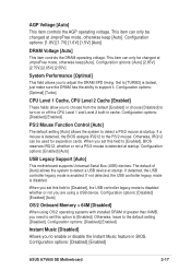
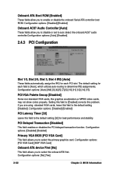
If you are using standard VGA cards, leave this problem. Setting this field to [Enabled] corrects this field to the default setting [Disabled]. PCI Delayed Transaction [Disabled] This field enables or disables the PCI delayed transaction function. Configuration options: [No] [Yes] 2-22 Chapter 2: BIOS Information Onboard ATA Boot ROM [Enabled] These fields allow you...
If you are using standard VGA cards, leave this problem. Setting this field to [Enabled] corrects this field to the default setting [Disabled]. PCI Delayed Transaction [Disabled] This field enables or disables the PCI delayed transaction function. Configuration options: [No] [Yes] 2-22 Chapter 2: BIOS Information Onboard ATA Boot ROM [Enabled] These fields allow you...
Motherboard DIY Troubleshooting Guide
Page 62
... Configuration options: [Disabled] [1~2 Min] [2~3 Min] [4~5 min] [8~9 Min] [20 Min] [30 Min] PWR Button < 4 Secs [Soft Off] When set in the Power Management Properties dialog box. Configuration options: [Blank Screen] [V/H SYNC+Blank] [DPMS Standby] [DPMS Suspend] [DPMS OFF] [DPMS Reduce ON] ...item "Advanced" in this feature, the +5VSB of the setting, holding the ATX switch for more than 4 seconds powers off ] [Suspend] 2-24 Chapter 2: BIOS Information Configuration options: [Disabled] [Enabled] Suspend Mode [Disabled] Sets the time period before the system goes into suspend mode....
... Configuration options: [Disabled] [1~2 Min] [2~3 Min] [4~5 min] [8~9 Min] [20 Min] [30 Min] PWR Button < 4 Secs [Soft Off] When set in the Power Management Properties dialog box. Configuration options: [Blank Screen] [V/H SYNC+Blank] [DPMS Standby] [DPMS Suspend] [DPMS OFF] [DPMS Reduce ON] ...item "Advanced" in this feature, the +5VSB of the setting, holding the ATX switch for more than 4 seconds powers off ] [Suspend] 2-24 Chapter 2: BIOS Information Configuration options: [Disabled] [Enabled] Suspend Mode [Disabled] Sets the time period before the system goes into suspend mode....
Motherboard DIY Troubleshooting Guide
Page 64
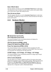
...+5V Voltage, +12V Voltage The onboard hardware monitor automatically detects the voltage output through the onboard voltage regulators. This allows you set to [Enabled], the Fan Speed Ratio and Speed Up/Down Response Time items appear to allow selection of the appropriate fan speeds... per minute (RPM). Configuration options: [Disabled] [Enabled] 2-26 Chapter 2: BIOS Information This allows you set the time of alarm after setting this field is not connected to enable or disable the ASUS Q-Fan feature that field shows N/A. When this item. Date of Month Alarm This...
...+5V Voltage, +12V Voltage The onboard hardware monitor automatically detects the voltage output through the onboard voltage regulators. This allows you set to [Enabled], the Fan Speed Ratio and Speed Up/Down Response Time items appear to allow selection of the appropriate fan speeds... per minute (RPM). Configuration options: [Disabled] [Enabled] 2-26 Chapter 2: BIOS Information This allows you set the time of alarm after setting this field is not connected to enable or disable the ASUS Q-Fan feature that field shows N/A. When this item. Date of Month Alarm This...
Motherboard DIY Troubleshooting Guide
Page 66
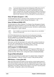
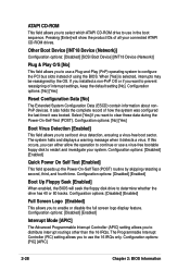
...ESCD) contain information about nonPnP devices. Configuration options: [Disabled] [Enabled] Interrupt Mode [APIC] The Advanced Programmable Interrupt Controller (APIC) setting allows you to enable or disable the full screen logo display feature. It also holds the complete record of all your system. Other Boot... field allows you to use the 16 IRQs only. Select [Yes] if you want to prevent reassigning of using the BIOS. The Programmable Interrupt Controller (PIC) setting allows you to use a Plug-and-Play (PnP) operating system to configure the PCI bus slots instead of interrupt...
...ESCD) contain information about nonPnP devices. Configuration options: [Disabled] [Enabled] Interrupt Mode [APIC] The Advanced Programmable Interrupt Controller (APIC) setting allows you to enable or disable the full screen logo display feature. It also holds the complete record of all your system. Other Boot... field allows you to use the 16 IRQs only. Select [Yes] if you want to prevent reassigning of using the BIOS. The Programmable Interrupt Controller (PIC) setting allows you to use a Plug-and-Play (PnP) operating system to configure the PCI bus slots instead of interrupt...
Motherboard DIY Troubleshooting Guide
Page 73
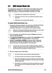
...) to Enabled. The Caps Lock LED is fixed to use for the connector location. When set it to the 4-pin CD-In connector (labeled CD1) on sound card. 3. ASUS A7V600 SE Motherboard 3-5 Instant Music Lite does not work if you wish to ON after enabling Instant Music...This feature is equipped with a BIOS-based audio playback feature called Instant Music Lite. Instant Music Lite only supports PS/2 keyboard. To enable ASUS Instant Music Lite: 1. In the Advanced Configuration menu, select the item Instant Music and set to set Instant Music CDROM item. If you...
...) to Enabled. The Caps Lock LED is fixed to use for the connector location. When set it to the 4-pin CD-In connector (labeled CD1) on sound card. 3. ASUS A7V600 SE Motherboard 3-5 Instant Music Lite does not work if you wish to ON after enabling Instant Music...This feature is equipped with a BIOS-based audio playback feature called Instant Music Lite. Instant Music Lite only supports PS/2 keyboard. To enable ASUS Instant Music Lite: 1. In the Advanced Configuration menu, select the item Instant Music and set to set Instant Music CDROM item. If you...

Motherboard DIY Troubleshooting Guide
Page 74
... to the Instant Music function key definitions on the drive and you enabled the Instant Music Lite in BIOS. DOWN VOL. If there is plugged to the Line Out (lime colored) port on the drive. ...6. Press F2 or Enter one of the two sets of special function keys on your keyboard to play the first track on the CD-ROM drive front ...to stop playing the CD. Press F2 or Enter once to the headphone jack on the CD. To use ASUS Instant Music Lite: 1. DOWN VOL. These keys only function as indicated if you press F1 or Space ...
... to the Instant Music function key definitions on the drive and you enabled the Instant Music Lite in BIOS. DOWN VOL. If there is plugged to the Line Out (lime colored) port on the drive. ...6. Press F2 or Enter one of the two sets of special function keys on your keyboard to play the first track on the CD-ROM drive front ...to stop playing the CD. Press F2 or Enter once to the headphone jack on the CD. To use ASUS Instant Music Lite: 1. DOWN VOL. These keys only function as indicated if you press F1 or Space ...


