
Motherboard DIY Troubleshooting Guide
Page 14
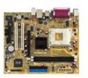
... RST 2 1 462 ZIF. 2 90°. У ! 14 ASUS A7S8X-MX усский 1 PS/2KBMS T: Mouse B: Keyboard CPU_FAN1 SPDIF_O Socket 462 DDR DIMM1 (64/72 bit, 184-pin module) DDR DIMM2 (64/72 bit, 184-pin module) ATXPWR PARALLEL PORT VGA1 USBPW1234 A7S8X-MX T:USB4 B:USB3 REL8201CL USB2.0 Top: T: USB1 RJ-45...
... RST 2 1 462 ZIF. 2 90°. У ! 14 ASUS A7S8X-MX усский 1 PS/2KBMS T: Mouse B: Keyboard CPU_FAN1 SPDIF_O Socket 462 DDR DIMM1 (64/72 bit, 184-pin module) DDR DIMM2 (64/72 bit, 184-pin module) ATXPWR PARALLEL PORT VGA1 USBPW1234 A7S8X-MX T:USB4 B:USB3 REL8201CL USB2.0 Top: T: USB1 RJ-45...
User manual for A7S8X-MX
Page 13
This chapter describes the motherboard features and the new technologies it supports. 1Product introduction ASUS A7S8X-MX 1-1
This chapter describes the motherboard features and the new technologies it supports. 1Product introduction ASUS A7S8X-MX 1-1
User manual for A7S8X-MX
Page 14
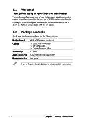
...with the list below. 1.2 Package contents Check your motherboard package for buying an ASUS® A7S8X-MX motherboard! Before you for the following items. Motherboard Cables Accessory Application CD Documentation ASUS A7S8X-MX motherboard 1 x Serial port (COM) cable 1 x Ultra DMA cable 1 x... Floppy disk drive cable I/O shield ASUS motherboard support CD User guide If any of ASUS quality motherboards! The motherboard delivers a host ...
...with the list below. 1.2 Package contents Check your motherboard package for buying an ASUS® A7S8X-MX motherboard! Before you for the following items. Motherboard Cables Accessory Application CD Documentation ASUS A7S8X-MX motherboard 1 x Serial port (COM) cable 1 x Ultra DMA cable 1 x... Floppy disk drive cable I/O shield ASUS motherboard support CD User guide If any of ASUS quality motherboards! The motherboard delivers a host ...
User manual for A7S8X-MX
Page 15
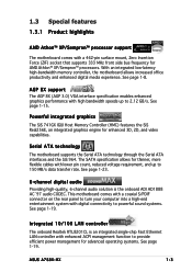
... office productivity and enhanced digital media experience. Integrated 10/100 LAN controller The onboard Realtek RTL8201CL is the onboard ADI AD1888 AC`97 audio CODEC. ASUS A7S8X-MX 1-3
... office productivity and enhanced digital media experience. Integrated 10/100 LAN controller The onboard Realtek RTL8201CL is the onboard ADI AD1888 AC`97 audio CODEC. ASUS A7S8X-MX 1-3

User manual for A7S8X-MX
Page 17
This is ON, in sleep mode, or in soft-off or the p o w e r c o r d i s d e t a c h e d f r o m t h e p o w e r s u p p l y . A7S8X-MX ® A7S8X-MX Onboard LED SB_PWR1 ON Standby Power OFF Powered Off ASUS A7S8X-MX 1-5 The illustration below shows the location of the following precautions before you install motherboard components or change any motherboard settings. • Unplug the power cord ...
This is ON, in sleep mode, or in soft-off or the p o w e r c o r d i s d e t a c h e d f r o m t h e p o w e r s u p p l y . A7S8X-MX ® A7S8X-MX Onboard LED SB_PWR1 ON Standby Power OFF Powered Off ASUS A7S8X-MX 1-5 The illustration below shows the location of the following precautions before you install motherboard components or change any motherboard settings. • Unplug the power cord ...
User manual for A7S8X-MX
Page 19
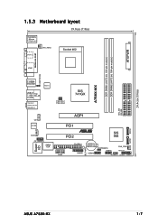
... CPU_FAN1 SPDIF_O Socket 462 DDR DIMM1 (64/72 bit, 184-pin module) DDR DIMM2 (64/72 bit, 184-pin module) ATXPWR PARALLEL PORT VGA1 USBPW1234 A7S8X-MX T:USB4 B:USB3 REL8201CL USB2.0 Top: T: USB1 RJ-45 B: USB2 Top:Line In Center:Line Out Below:Mic In FSB_SEL1 FSB_SEL0 SIS 741GX SEC_IDE PRI_IDE Super... PCI2 964 COM1 FLOPPY1 GAME1 CR2032 3V Lithium Cell CMOS Power USBPW5678 CHA_FAN1 USB78 PWRLED1 USB56 SPEAKER1 CLRTC1 PANEL1 24.4cm (9.6in) SB_PWR1 SATA1 SATA2 ASUS A7S8X-MX 1-7
... CPU_FAN1 SPDIF_O Socket 462 DDR DIMM1 (64/72 bit, 184-pin module) DDR DIMM2 (64/72 bit, 184-pin module) ATXPWR PARALLEL PORT VGA1 USBPW1234 A7S8X-MX T:USB4 B:USB3 REL8201CL USB2.0 Top: T: USB1 RJ-45 B: USB2 Top:Line In Center:Line Out Below:Mic In FSB_SEL1 FSB_SEL0 SIS 741GX SEC_IDE PRI_IDE Super... PCI2 964 COM1 FLOPPY1 GAME1 CR2032 3V Lithium Cell CMOS Power USBPW5678 CHA_FAN1 USB78 PWRLED1 USB56 SPEAKER1 CLRTC1 PANEL1 24.4cm (9.6in) SB_PWR1 SATA1 SATA2 ASUS A7S8X-MX 1-7
User manual for A7S8X-MX
Page 21
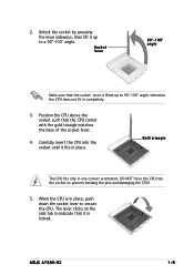
... into the socket to 90°-100° angle; otherwise the CPU does not fit in one correct orientation. When the CPU is in place. ASUS A7S8X-MX 1-9 Position the CPU above the socket such that it fits in place, push down the socket lever to a 90°-100° angle. Unlock the...
... into the socket to 90°-100° angle; otherwise the CPU does not fit in one correct orientation. When the CPU is in place. ASUS A7S8X-MX 1-9 Position the CPU above the socket such that it fits in place, push down the socket lever to a 90°-100° angle. Unlock the...
User manual for A7S8X-MX
Page 25
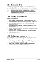
... it and make the necessary hardware settings for information on the system and change the necessary BIOS settings, if any. See Chapter 2 for the card. 2. ASUS A7S8X-MX 1-13 1.8 Expansion slots In the future, you may cause you removed earlier. 6. Before installing the expansion card, read the documentation that came with the slot...
... it and make the necessary hardware settings for information on the system and change the necessary BIOS settings, if any. See Chapter 2 for the card. 2. ASUS A7S8X-MX 1-13 1.8 Expansion slots In the future, you may cause you removed earlier. 6. Before installing the expansion card, read the documentation that came with the slot...

User manual for A7S8X-MX
Page 27
..., and other cards that they fit the AGP slot on this motherboard! When you buy an AGP card, make sure that supports +1.5V AGP cards. A7S8X-MX ASUS A7S8X-MX 1-15 1.8.4 PCI slots This motherboard has two PCI slots. The figure shows a LAN card installed on a PCI slot. 1.8.5 AGP slot This motherboard has... an Accelerated Graphics Port (AGP) slot that you ask for 1.5v A7S8X-MX Accelerated Graphics Port (AGP1) Install only 1.5V AGP cards on your motherboard. ® Keyed for one with PCI specifications.
..., and other cards that they fit the AGP slot on this motherboard! When you buy an AGP card, make sure that supports +1.5V AGP cards. A7S8X-MX ASUS A7S8X-MX 1-15 1.8.4 PCI slots This motherboard has two PCI slots. The figure shows a LAN card installed on a PCI slot. 1.8.5 AGP slot This motherboard has... an Accelerated Graphics Port (AGP) slot that you ask for 1.5v A7S8X-MX Accelerated Graphics Port (AGP1) Install only 1.5V AGP cards on your motherboard. ® Keyed for one with PCI specifications.
User manual for A7S8X-MX
Page 29
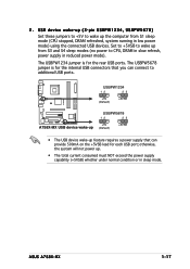
... (3-pin USBPW1234, USBPW5678) Set these jumpers to +5V to CPU, DRAM in slow refresh, power supply in low power mode) using the connected USB devices. ASUS A7S8X-MX 1-17 USB device wake-up feature requires a power supply that can provide 500mA on the +5VSB lead for the internal USB connectors that you can...
... (3-pin USBPW1234, USBPW5678) Set these jumpers to +5V to CPU, DRAM in slow refresh, power supply in low power mode) using the connected USB devices. ASUS A7S8X-MX 1-17 USB device wake-up feature requires a power supply that can provide 500mA on the +5VSB lead for the internal USB connectors that you can...
User manual for A7S8X-MX
Page 31
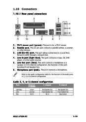
... Lime Pink Line In Line Out Mic In Rear Speaker Out Front Speaker Out Mic In 6-channel Rear Speaker Out Front Speaker Out Bass/Center ASUS A7S8X-MX 1-19 This port connects a microphone.
... Lime Pink Line In Line Out Mic In Rear Speaker Out Front Speaker Out Mic In 6-channel Rear Speaker Out Front Speaker Out Bass/Center ASUS A7S8X-MX 1-19 This port connects a microphone.
User manual for A7S8X-MX
Page 33
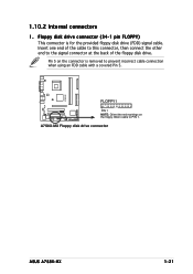
Pin 5 on the floppy ribbon cable to PIN 1. A7S8X-MX Floppy disk drive connector ASUS A7S8X-MX 1-21 1.10.2 Internal connectors 1 . Floppy disk drive connector (34-1 pin FLOPPY) This connector is removed to the signal connector at the back of the floppy disk drive. Insert one end of the cable to this connector, then connect the other end to prevent incorrect cable connection when using an FDD cable with a covered Pin 5. A7S8X-MX FLOPPY1 ® PIN 1 NOTE: Orient the red markings on the connector is for the provided floppy disk drive (FDD) signal cable.
Pin 5 on the floppy ribbon cable to PIN 1. A7S8X-MX Floppy disk drive connector ASUS A7S8X-MX 1-21 1.10.2 Internal connectors 1 . Floppy disk drive connector (34-1 pin FLOPPY) This connector is removed to the signal connector at the back of the floppy disk drive. Insert one end of the cable to this connector, then connect the other end to prevent incorrect cable connection when using an FDD cable with a covered Pin 5. A7S8X-MX FLOPPY1 ® PIN 1 NOTE: Orient the red markings on the connector is for the provided floppy disk drive (FDD) signal cable.

User manual for A7S8X-MX
Page 35
Refer to support S3 function. A7S8X-MX ® A7S8X-MX SATA connectors SATA2 GND RSATA_TXP2 RSATA_TXN2 GND RSATA_RXP2 RSATA_RXN2 GND SATA1 GND RSATA_TXP1 RSATA_TXN1 GND RSATA_RXP1 RSATA_RXN1 GND Important notes on the master port (SATA1) ... SE/Me, do not support native Serial ATA mode. Serial ATA Master/Slave connectors Connector SATA1 SATA2 Setting Master Slave Use Boot disk Data disk ASUS A7S8X-MX 1-23 Serial ATA connectors (7-pin SATA1, SATA2) These connectors are for the Serial ATA signal cables for details. 3. See page 2-23. • Plug your Serial...
Refer to support S3 function. A7S8X-MX ® A7S8X-MX SATA connectors SATA2 GND RSATA_TXP2 RSATA_TXN2 GND RSATA_RXP2 RSATA_RXN2 GND SATA1 GND RSATA_TXP1 RSATA_TXN1 GND RSATA_RXP1 RSATA_RXN1 GND Important notes on the master port (SATA1) ... SE/Me, do not support native Serial ATA mode. Serial ATA Master/Slave connectors Connector SATA1 SATA2 Setting Master Slave Use Boot disk Data disk ASUS A7S8X-MX 1-23 Serial ATA connectors (7-pin SATA1, SATA2) These connectors are for the Serial ATA signal cables for details. 3. See page 2-23. • Plug your Serial...
User manual for A7S8X-MX
Page 37
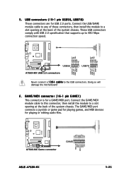
... USB_P8USB_P8+ GND NC USB+5V USB_P6USB_P6+ GND NC USB+7V USB_P7USB_P7+ GND USB+5V USB_P5USB_P5+ GND ® USB56 1 A7S8X-MX USB 2.0 connectors USB78 1 Never connect a 1 3 9 4 c a b l e to a slot opening at the back of the system chassis. The GAME/MIDI port connects a ... Connect the GAME/MIDI module cable to this connector, then install the module to 480 Mbps connection speed. A7S8X-MX +5V J1B2 J1CY GND GND J1CX J1B1 +5V ® A7S8X-MX Game connector GAME ASUS A7S8X-MX MIDI_IN J2B2 J2CY MIDI_OUT J2CX J2B1 +5V 1-25 GAME/MIDI connector (16-1 pin GAME1) This connector is...
... USB_P8USB_P8+ GND NC USB+5V USB_P6USB_P6+ GND NC USB+7V USB_P7USB_P7+ GND USB+5V USB_P5USB_P5+ GND ® USB56 1 A7S8X-MX USB 2.0 connectors USB78 1 Never connect a 1 3 9 4 c a b l e to a slot opening at the back of the system chassis. The GAME/MIDI port connects a ... Connect the GAME/MIDI module cable to this connector, then install the module to 480 Mbps connection speed. A7S8X-MX +5V J1B2 J1CY GND GND J1CX J1B1 +5V ® A7S8X-MX Game connector GAME ASUS A7S8X-MX MIDI_IN J2B2 J2CY MIDI_OUT J2CX J2B1 +5V 1-25 GAME/MIDI connector (16-1 pin GAME1) This connector is...
User manual for A7S8X-MX
Page 39
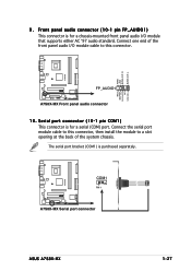
... a chassis-mounted front panel audio I /O module cable to this connector, then install the module to this connector. AGND +5VA BLINE_OUT_R BLINE_OUT_L A7S8X-MX MIC2 MICPWR Line out_R NC Line out_L 9 . FP_AUDIO1 ® A7S8X-MX Front panel audio connector 10. COM1 PIN 1 ® A7S8X-MX Serial port connector A7S8X-MX ASUS A7S8X-MX 1-27 The serial port bracket (COM1) is purchased separately.
... a chassis-mounted front panel audio I /O module cable to this connector, then install the module to this connector. AGND +5VA BLINE_OUT_R BLINE_OUT_L A7S8X-MX MIC2 MICPWR Line out_R NC Line out_L 9 . FP_AUDIO1 ® A7S8X-MX Front panel audio connector 10. COM1 PIN 1 ® A7S8X-MX Serial port connector A7S8X-MX ASUS A7S8X-MX 1-27 The serial port bracket (COM1) is purchased separately.
User manual for A7S8X-MX
Page 41
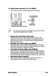
... up when you turn on the system power, and blinks when the system is in SLEEP or SOFT-OFF mode depending on the BIOS settings. ASUS A7S8X-MX 1-29 13. Pressing the power switch for more than four seconds while the system is ON turns the system OFF. • Reset button (Blue.... Refer to this connector. Connect the chassis power LED cable to the HDD. • Power/Soft-off the system power. Ground Reset ® A7S8X-MX System panel connector HDLED RST The sytem panel connector is read from or written to this connector. The system power LED lights up or flashes...
... up when you turn on the system power, and blinks when the system is in SLEEP or SOFT-OFF mode depending on the BIOS settings. ASUS A7S8X-MX 1-29 13. Pressing the power switch for more than four seconds while the system is ON turns the system OFF. • Reset button (Blue.... Refer to this connector. Connect the chassis power LED cable to the HDD. • Power/Soft-off the system power. Ground Reset ® A7S8X-MX System panel connector HDLED RST The sytem panel connector is read from or written to this connector. The system power LED lights up or flashes...
User manual for A7S8X-MX
Page 43
Detailed descriptions of the BIOS parameters are also provided. 2 BIOS setup ASUS A7S8X-MX 2-1 This chapter tells how to change the system settings through the BIOS Setup menus.
Detailed descriptions of the BIOS parameters are also provided. 2 BIOS setup ASUS A7S8X-MX 2-1 This chapter tells how to change the system settings through the BIOS Setup menus.
User manual for A7S8X-MX
Page 45
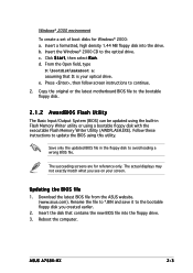
...Save only the updated BIOS file in Flash Memory Writer utility or using this utility. Insert the disk that D: is your screen. ASUS A7S8X-MX 2-3 Rename the file to *.BIN and save it to update the BIOS using a bootable floppy disk with the executable Flash Memory ...Writer Utility (AWDFLASH.EXE). c. d. Download the latest BIOS file from the ASUS website. (www.asus.com). Copy the original or the latest motherboard BIOS file to the optical drive. Reboot the computer. b. Click S t a r t, then select...
...Save only the updated BIOS file in Flash Memory Writer utility or using this utility. Insert the disk that D: is your screen. ASUS A7S8X-MX 2-3 Rename the file to *.BIN and save it to update the BIOS using a bootable floppy disk with the executable Flash Memory ...Writer Utility (AWDFLASH.EXE). c. d. Download the latest BIOS file from the ASUS website. (www.asus.com). Copy the original or the latest motherboard BIOS file to the optical drive. Reboot the computer. b. Click S t a r t, then select...
User manual for A7S8X-MX
Page 47
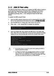
... to go through the long process of booting from a floppy disk and using EZ Flash: 1. Start erasing.......| Start programming...| Flashed successfully. ASUS A7S8X-MX 2-5 Press + during the Power-On Self Tests (POST). Floppy found !" error message appears if there is not found in the floppy disk... floppy disk, then restart the system. 3. Visit the ASUS website (www.asus.com) to download the latest BIOS file for the motherboard and rename the same to A7S8X-MX.ROM. EZFlash starting BIOS update Checking for floppy... An "A7S8X-MX.ROM not found ! Make sure that contains the BIOS ...
... to go through the long process of booting from a floppy disk and using EZ Flash: 1. Start erasing.......| Start programming...| Flashed successfully. ASUS A7S8X-MX 2-5 Press + during the Power-On Self Tests (POST). Floppy found !" error message appears if there is not found in the floppy disk... floppy disk, then restart the system. 3. Visit the ASUS website (www.asus.com) to download the latest BIOS file for the motherboard and rename the same to A7S8X-MX.ROM. EZFlash starting BIOS update Checking for floppy... An "A7S8X-MX.ROM not found ! Make sure that contains the BIOS ...
User manual for A7S8X-MX
Page 49
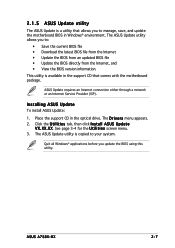
... motherboard BIOS in the support CD that comes with the motherboard package. Click the U t i l i t i e s tab, then click I n s t a l l A S U S U p d a t e V X . ASUS A7S8X-MX 2-7 Quit all Windows® applications before you update the BIOS using this utility. The D r i v e r s menu appears. 2. ASUS Update requires an Internet connection either through a network or an Internet Service Provider (ISP). Place the support...
... motherboard BIOS in the support CD that comes with the motherboard package. Click the U t i l i t i e s tab, then click I n s t a l l A S U S U p d a t e V X . ASUS A7S8X-MX 2-7 Quit all Windows® applications before you update the BIOS using this utility. The D r i v e r s menu appears. 2. ASUS Update requires an Internet connection either through a network or an Internet Service Provider (ISP). Place the support...


