
A7S-VM User Manual
Page 1
® A7S-VM SiS730S Ultra-AGP Socket A Motherboard USER'S MANUAL
® A7S-VM SiS730S Ultra-AGP Socket A Motherboard USER'S MANUAL
A7S-VM User Manual
Page 2
... PRODUCT. Copyright © 2001 ASUSTeK COMPUTER INC. Product Name: ASUS A7S-VM Manual Revision: 1.03 E762 Release Date: April 2001 2 ASUS A7S-VM User's Manual The product name and revision number are trademarks of Trend Micro Incorporated. Manual revisions are represented by the third digit in this manual, including the products and software described in it, may not be registered trademarks...
... PRODUCT. Copyright © 2001 ASUSTeK COMPUTER INC. Product Name: ASUS A7S-VM Manual Revision: 1.03 E762 Release Date: April 2001 2 ASUS A7S-VM User's Manual The product name and revision number are trademarks of Trend Micro Incorporated. Manual revisions are represented by the third digit in this manual, including the products and software described in it, may not be registered trademarks...
A7S-VM User Manual
Page 3
...) Notebook (Tel): +886-2-2890-7122 (English) Desktop/Server (Tel):+886-2-2890-7123 (English) Fax: +886-2-2893-7775 Email: tsd@asus.com.tw WWW: www.asus.com.tw FTP: ftp.asus.com.tw/pub/ASUS ASUS COMPUTER INTERNATIONAL (America) Marketing Address: 6737 Mowry Avenue, Mowry Business Center, Building 2 Newark, CA 94560, USA Fax: +1-510-608-4555... Fax: +49-2102-9599-11 Support (Email): www.asuscom.de/de/support (for online support) WWW: www.asuscom.de FTP: ftp.asuscom.de/pub/ASUSCOM ASUS A7S-VM User's Manual 3
...) Notebook (Tel): +886-2-2890-7122 (English) Desktop/Server (Tel):+886-2-2890-7123 (English) Fax: +886-2-2893-7775 Email: tsd@asus.com.tw WWW: www.asus.com.tw FTP: ftp.asus.com.tw/pub/ASUS ASUS COMPUTER INTERNATIONAL (America) Marketing Address: 6737 Mowry Avenue, Mowry Business Center, Building 2 Newark, CA 94560, USA Fax: +1-510-608-4555... Fax: +49-2102-9599-11 Support (Email): www.asuscom.de/de/support (for online support) WWW: www.asuscom.de FTP: ftp.asuscom.de/pub/ASUSCOM ASUS A7S-VM User's Manual 3

A7S-VM User Manual
Page 4
INTRODUCTION 7 1.1 How This Manual Is Organized 7 1.2 Item Checklist 7 2. HARDWARE SETUP 14 3.1 Motherboard Layout 14 3.2 Layout Contents 15 3.3 Hardware Setup Procedure 16 3.4 ...2.1 ASUS A7S-VM Motherboard 8 2.1.1 Specifications 8 2.1.2 Performance 10 2.1.3 Intelligence 11 2.2 Motherboard Components 12 2.2.1 Component Locations 13 3. BIOS SETUP 41 4.1 Managing and Updating Your BIOS 41 4.1.1 Upon First Use of the Computer System 41 4.1.2 Updating BIOS Procedures 43 4.2 BIOS Setup Program 45 4.2.1 BIOS Menu Bar 46 4.2.2 Legend Bar 46 4 ASUS A7S-VM User's Manual
INTRODUCTION 7 1.1 How This Manual Is Organized 7 1.2 Item Checklist 7 2. HARDWARE SETUP 14 3.1 Motherboard Layout 14 3.2 Layout Contents 15 3.3 Hardware Setup Procedure 16 3.4 ...2.1 ASUS A7S-VM Motherboard 8 2.1.1 Specifications 8 2.1.2 Performance 10 2.1.3 Intelligence 11 2.2 Motherboard Components 12 2.2.1 Component Locations 13 3. BIOS SETUP 41 4.1 Managing and Updating Your BIOS 41 4.1.1 Upon First Use of the Computer System 41 4.1.2 Updating BIOS Procedures 43 4.2 BIOS Setup Program 45 4.2.1 BIOS Menu Bar 46 4.2.2 Legend Bar 46 4 ASUS A7S-VM User's Manual
A7S-VM User Manual
Page 5
... 4.4.4 Shadow Configuration 65 4.5 Power Menu 66 4.5.1 Power Up Control 68 4.5.2 Hardware Monitor 69 4.6 Boot Menu 70 4.7 Exit Menu 72 5. SOFTWARE REFERENCE 77 6.1 ASUS PC Probe 77 7. SOFTWARE SETUP 75 5.1 Operating Systems 75 5.1.1 Windows 98 First Time Installation 75 5.2 A7S-VM Motherboard Support CD 75 5.2.1 Installation Menus 75 6. APPENDIX 83 7.1 Glossary 83 INDEX 87 ASUS A7S-VM User's Manual 5
... 4.4.4 Shadow Configuration 65 4.5 Power Menu 66 4.5.1 Power Up Control 68 4.5.2 Hardware Monitor 69 4.6 Boot Menu 70 4.7 Exit Menu 72 5. SOFTWARE REFERENCE 77 6.1 ASUS PC Probe 77 7. SOFTWARE SETUP 75 5.1 Operating Systems 75 5.1.1 Windows 98 First Time Installation 75 5.2 A7S-VM Motherboard Support CD 75 5.2.1 Installation Menus 75 6. APPENDIX 83 7.1 Glossary 83 INDEX 87 ASUS A7S-VM User's Manual 5
A7S-VM User Manual
Page 6
... modifications to radio communications. This equipment generates, uses and can be determined by turning the equipment off and on, the user is encouraged to try to correct the interference by the manufacturer could result in a residential installation. If this product not ...installation. Government Printing Office. Cet appareil numérique de la classe B est conforme à la norme NMB-003 du Canada. 6 ASUS A7S-VM User's Manual Canadian Department of the FCC Rules. Washington DC: Office of Federal Regulations #47, part 15.193, 1993. However, there is connected. ...
... modifications to radio communications. This equipment generates, uses and can be determined by turning the equipment off and on, the user is encouraged to try to correct the interference by the manufacturer could result in a residential installation. If this product not ...installation. Government Printing Office. Cet appareil numérique de la classe B est conforme à la norme NMB-003 du Canada. 6 ASUS A7S-VM User's Manual Canadian Department of the FCC Rules. Washington DC: Office of Federal Regulations #47, part 15.193, 1993. However, there is connected. ...

A7S-VM User Manual
Page 7
... that your retailer. INTRODUCTION Manual / Checklist 1. If you discover damaged or missing items, contact your package is divided into the following sections: 1. INTRODUCTION 2. SOFTWARE SETUP 6. FEATURES 3. INTRODUCTION 1.1 How This Manual Is Organized This manual is complete. HARDWARE SETUP 4. SOFTWARE REFERENCE 7. Instructions on setting up the BIOS Instructions on LAN models only) (1) User's Manual ASUS A7S-VM User's Manual 7 1. BIOS SETUP...
... that your retailer. INTRODUCTION Manual / Checklist 1. If you discover damaged or missing items, contact your package is divided into the following sections: 1. INTRODUCTION 2. SOFTWARE SETUP 6. FEATURES 3. INTRODUCTION 1.1 How This Manual Is Organized This manual is complete. HARDWARE SETUP 4. SOFTWARE REFERENCE 7. Instructions on setting up the BIOS Instructions on LAN models only) (1) User's Manual ASUS A7S-VM User's Manual 7 1. BIOS SETUP...

A7S-VM User Manual
Page 8
.../South Bridge System Chipset: Features the SiS730S single chip that complements the powers of frequency and Vcore voltage through the onboard hardware ASUS ASIC and the bundled ASUS PC Probe. 8 ASUS A7S-VM User's Manual The motherboard is enabled. • UltraDMA/100 Support: Comes with an onboard PCI Bus Master IDE controller with EPP and ECP capabilities...
.../South Bridge System Chipset: Features the SiS730S single chip that complements the powers of frequency and Vcore voltage through the onboard hardware ASUS ASIC and the bundled ASUS PC Probe. 8 ASUS A7S-VM User's Manual The motherboard is enabled. • UltraDMA/100 Support: Comes with an onboard PCI Bus Master IDE controller with EPP and ECP capabilities...

A7S-VM User Manual
Page 9
... that support integrated audio and modem features that comprise digital audio engine with system diagnostic display area, system status LEDs, USB ports, and hot keys. ASUS A7S-VM User's Manual 9 FEATURES Specifications 2. The AFPANEL connector on -chip sample rate converter, and a professional wavetable. • Connectivity Interface: Supports an optional...
... that support integrated audio and modem features that comprise digital audio engine with system diagnostic display area, system status LEDs, USB ports, and hot keys. ASUS A7S-VM User's Manual 9 FEATURES Specifications 2. The AFPANEL connector on -chip sample rate converter, and a professional wavetable. • Connectivity Interface: Supports an optional...

A7S-VM User Manual
Page 10
2. Color-coded connectors and descriptive icons make identification easy as Windows 98/2000/Millenium. • PC'99 Compliant: Both the BIOS and hardware levels of ASUS smart series motherboards are based on the following high-level goals: Support for Plugn-Play compatibility and power management for configuring and managing all system ... requires a 40-pin 80-conductor cable). • Concurrent PCI: Concurrent PCI allows multiple PCI transfers from PCI master busses to the memory and processor. 10 ASUS A7S-VM User's Manual
2. Color-coded connectors and descriptive icons make identification easy as Windows 98/2000/Millenium. • PC'99 Compliant: Both the BIOS and hardware levels of ASUS smart series motherboards are based on the following high-level goals: Support for Plugn-Play compatibility and power management for configuring and managing all system ... requires a 40-pin 80-conductor cable). • Concurrent PCI: Concurrent PCI allows multiple PCI transfers from PCI master busses to the memory and processor. 10 ASUS A7S-VM User's Manual
A7S-VM User Manual
Page 11
...ensure proper system configuration and management. • Chassis Intrusion Detection: Supports chassis-intrusion monitoring through the ASUS ASIC. FEATURES Intelligence 2. The system resource monitor warns the user before the system resources are set for its normal RPM range and alarm thresholds. • Power LED...the BIOS or OS setting (see PWR Button < 4 Secs in sleep mode. ASUS A7S-VM User's Manual 11 When you to present enormous user interfaces and run large applications. With this benefit onhand, users can be monitored for more memory and hard drive space to turn off the ...
...ensure proper system configuration and management. • Chassis Intrusion Detection: Supports chassis-intrusion monitoring through the ASUS ASIC. FEATURES Intelligence 2. The system resource monitor warns the user before the system resources are set for its normal RPM range and alarm thresholds. • Power LED...the BIOS or OS setting (see PWR Button < 4 Secs in sleep mode. ASUS A7S-VM User's Manual 11 When you to present enormous user interfaces and run large applications. With this benefit onhand, users can be monitored for more memory and hard drive space to turn off the ...
A7S-VM User Manual
Page 12
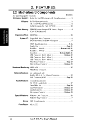
...SDRAM support Expansion Slots 4 PCI Slots 18 System I/O Floppy Disk Drive Connector 6 IDE Connectors (UltraDMA/100 Support 5 ASUS iPanel Connectors 9, 16 Parallel Port Top) 21 Serial Port 1 (COM1 Bottom Left) 21 Serial Port 2 (COM2 14...11 USB Connectors (Port 4 & Port 5 13 PS/2 Mouse Connector Top) 23 PS/2 Keyboard Connector Bottom) 23 Hardware Monitoring ASUS ASIC 15 3 Fan Power Connectors Network Features (on LAN models only) RealTek RTL8100 Fast Ethernet Controller 19 LAN Connector (RJ-45 ... Power ATX Power Connector 1 Form Factor Micro ATX 12 ASUS A7S-VM User's Manual
...SDRAM support Expansion Slots 4 PCI Slots 18 System I/O Floppy Disk Drive Connector 6 IDE Connectors (UltraDMA/100 Support 5 ASUS iPanel Connectors 9, 16 Parallel Port Top) 21 Serial Port 1 (COM1 Bottom Left) 21 Serial Port 2 (COM2 14...11 USB Connectors (Port 4 & Port 5 13 PS/2 Mouse Connector Top) 23 PS/2 Keyboard Connector Bottom) 23 Hardware Monitoring ASUS ASIC 15 3 Fan Power Connectors Network Features (on LAN models only) RealTek RTL8100 Fast Ethernet Controller 19 LAN Connector (RJ-45 ... Power ATX Power Connector 1 Form Factor Micro ATX 12 ASUS A7S-VM User's Manual
A7S-VM User Manual
Page 14
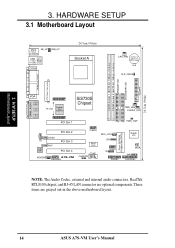
... 3 PCI Slot 4 MODEM A7S-VM AAPANEL USBP2 ASUS ASIC COM2 CHASSIS WOL_CON CIR USBP1 IR PANEL Flash EEPROM (Programable BIOS) Super I/O WOR SMB AFPANEL NOTE: The Audio Codec, external and internal audio connectors, RealTek RTL8100 chipset, and RJ-45 LAN connector are grayed out in the above motherboard layout. 14 ASUS A7S-VM User's Manual These items are...
... 3 PCI Slot 4 MODEM A7S-VM AAPANEL USBP2 ASUS ASIC COM2 CHASSIS WOL_CON CIR USBP1 IR PANEL Flash EEPROM (Programable BIOS) Super I/O WOR SMB AFPANEL NOTE: The Audio Codec, external and internal audio connectors, RealTek RTL8100 chipset, and RJ-45 LAN connector are grayed out in the above motherboard layout. 14 ASUS A7S-VM User's Manual These items are...

A7S-VM User Manual
Page 15
... Fan Connectors (3-pin) p. 32 Chassis Intrusion Lead (4-1 pin) p. 32 SMBus Connector (5-1 pin) p. 33 Standard Infrared Module Connector (5-pin) p. 33 Consumer Infrared Module Connector (5-pin) p. 34 ASUS iPanel Connector (12-1 pin) p. 34 Audio Panel Connector (12-1 pin) p. 35 USB Headers (two 10-1 pin) p. 35 Internal Audio Connectors (4-1 pin) p. 36 LCD Headers (two... (4-pin) p. 38 System Message LED Lead (2-pin) p. 38 System Management Interrupt Lead (2-pin) p. 38 ATX / Soft-Off Switch Lead (2-pin) p. 38 Reset Switch Lead (2-pin) ASUS A7S-VM User's Manual 15 3.
... Fan Connectors (3-pin) p. 32 Chassis Intrusion Lead (4-1 pin) p. 32 SMBus Connector (5-1 pin) p. 33 Standard Infrared Module Connector (5-pin) p. 33 Consumer Infrared Module Connector (5-pin) p. 34 ASUS iPanel Connector (12-1 pin) p. 34 Audio Panel Connector (12-1 pin) p. 35 USB Headers (two 10-1 pin) p. 35 Internal Audio Connectors (4-1 pin) p. 36 LCD Headers (two... (4-pin) p. 38 System Message LED Lead (2-pin) p. 38 System Management Interrupt Lead (2-pin) p. 38 ATX / Soft-Off Switch Lead (2-pin) p. 38 Reset Switch Lead (2-pin) ASUS A7S-VM User's Manual 15 3.
A7S-VM User Manual
Page 16
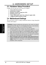
... motherboard settings 2. Hold components by the edges and try not to change motherboard function settings through the switches and/or jumpers. H/W SETUP Motherboard Settings 16 ASUS A7S-VM User's Manual Configure the BIOS parameter settings 3.4 Motherboard Settings This section tells you uninstall any component, ensure that came with the components. 5. Use a grounded wrist strap or...
... motherboard settings 2. Hold components by the edges and try not to change motherboard function settings through the switches and/or jumpers. H/W SETUP Motherboard Settings 16 ASUS A7S-VM User's Manual Configure the BIOS parameter settings 3.4 Motherboard Settings This section tells you uninstall any component, ensure that came with the components. 5. Use a grounded wrist strap or...

A7S-VM User Manual
Page 17
... to ENABLE if you wish to use the USB devices to enable or disable the keyboard wake up . 2. A7S-VM A7S-VM Keyboard Wake Up KB_UP 2 1 Disable (Default) 3 2 Enable ASUS A7S-VM User's Manual 17 This feature requires an ATX power supply that can supply at least 2A on the +5VSB lead. Before ... is DISABLE. The total current consumed must NOT exceed the power supply capability (+5VSB) whether under normal working conditions or in sleep mode. A7S-VM A7S-VM USB Wake Up USB_UP 2 1 Disable (Default) 3 2 Enable 2) Keyboard Wake-up Jumper (3-pin KB_UP) This jumper allows you to ...
... to ENABLE if you wish to use the USB devices to enable or disable the keyboard wake up . 2. A7S-VM A7S-VM Keyboard Wake Up KB_UP 2 1 Disable (Default) 3 2 Enable ASUS A7S-VM User's Manual 17 This feature requires an ATX power supply that can supply at least 2A on the +5VSB lead. Before ... is DISABLE. The total current consumed must NOT exceed the power supply capability (+5VSB) whether under normal working conditions or in sleep mode. A7S-VM A7S-VM USB Wake Up USB_UP 2 1 Disable (Default) 3 2 Enable 2) Keyboard Wake-up Jumper (3-pin KB_UP) This jumper allows you to ...
A7S-VM User Manual
Page 18
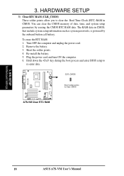
... data in CMOS. Hold down the key during the boot process and enter BIOS setup to Clear CMOS A7S-VM A7S-VM Clear RTC RAM 3. Re-install the battery. 5. Short the solder points. 4. H/W SETUP Motherboard Settings 18 ASUS A7S-VM User's Manual 3. You can clear the CMOS memory of date, time, and system setup parameters by the onboard button...
... data in CMOS. Hold down the key during the boot process and enter BIOS setup to Clear CMOS A7S-VM A7S-VM Clear RTC RAM 3. Re-install the battery. 5. Short the solder points. 4. H/W SETUP Motherboard Settings 18 ASUS A7S-VM User's Manual 3. You can clear the CMOS memory of date, time, and system setup parameters by the onboard button...

A7S-VM User Manual
Page 19
... up to operate 100MHz/133MHz, use can handle the specified SDRAM speeds, otherwise the computer will not boot. 3. H/W SETUP System Memory ASUS A7S-VM User's Manual 19 Make sure that have more than EDO (Extended Data Output) chips. • BIOS shows SDRAM memory on the motherboard. double-sided... come in 32, 64, 128, 256, 512MB. compliant DIMMs. • ASUS motherboards support Serial Presence Detect (SPD) DIMMs. This is the memory of choice for a system memory configuration of 16, 32, 64, 128, 256...
... up to operate 100MHz/133MHz, use can handle the specified SDRAM speeds, otherwise the computer will not boot. 3. H/W SETUP System Memory ASUS A7S-VM User's Manual 19 Make sure that have more than EDO (Extended Data Output) chips. • BIOS shows SDRAM memory on the motherboard. double-sided... come in 32, 64, 128, 256, 512MB. compliant DIMMs. • ASUS motherboards support Serial Presence Detect (SPD) DIMMs. This is the memory of choice for a system memory configuration of 16, 32, 64, 128, 256...

A7S-VM User Manual
Page 20
... fits in one direction. This motherboard supports four clock signals per DIMM. 20 ASUS A7S-VM User's Manual SDRAM DIMMs have different pin contacts on each side and have a higher pin density than DRAM SIMMs. 20 Pins 60 Pins 88 Pins A7S-VM A7S-VM 168-Pin DIMM Sockets Lock The DIMMs must tell your retailer the correct DIMM...
... fits in one direction. This motherboard supports four clock signals per DIMM. 20 ASUS A7S-VM User's Manual SDRAM DIMMs have different pin contacts on each side and have a higher pin density than DRAM SIMMs. 20 Pins 60 Pins 88 Pins A7S-VM A7S-VM 168-Pin DIMM Sockets Lock The DIMMs must tell your retailer the correct DIMM...
A7S-VM User Manual
Page 21
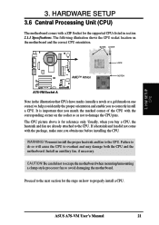
... socket so as not to correctly install a CPU. You must install the proper heatsink and fan to avoid damaging the motherboard. ASUS A7S-VM User's Manual 21 BLANK LEVER LOCK AMD™ Athlon NOTCH A7S-VM A7S-VM Socket A Note in section 2.1.1 Specifications. Failure to do so will cause the CPU to the CPU. Install an auxillary fan, if...
... socket so as not to correctly install a CPU. You must install the proper heatsink and fan to avoid damaging the motherboard. ASUS A7S-VM User's Manual 21 BLANK LEVER LOCK AMD™ Athlon NOTCH A7S-VM A7S-VM Socket A Note in section 2.1.1 Specifications. Failure to do so will cause the CPU to the CPU. Install an auxillary fan, if...

