
A7S-VM User Manual
Page 7
BIOS SETUP 5. Instructions on setting up the BIOS Instructions on setting up the included software Reference material for two 3.5" floppy disk drives (1) ASUS Support CD with drivers and utilities ASUS IrDA-compliant infrared module (1) Bag of spare jumper caps (1) ASUS 2-port USB Connector Set (1) I/O Plate (on setting up the motherboard. SOFTWARE REFERENCE 7. Package Contents (1) ASUS Motherboard Optional Items ASUS Modem MR (1) 40-pin 80-conductor ribbon cable for internal UltraDMA/ 100/66 or UltraDMA/33 IDE drives (1) Ribbon cable for the included software Optional items...
BIOS SETUP 5. Instructions on setting up the BIOS Instructions on setting up the included software Reference material for two 3.5" floppy disk drives (1) ASUS Support CD with drivers and utilities ASUS IrDA-compliant infrared module (1) Bag of spare jumper caps (1) ASUS 2-port USB Connector Set (1) I/O Plate (on setting up the motherboard. SOFTWARE REFERENCE 7. Package Contents (1) ASUS Motherboard Optional Items ASUS Modem MR (1) 40-pin 80-conductor ribbon cable for internal UltraDMA/ 100/66 or UltraDMA/33 IDE drives (1) Ribbon cable for the included software Optional items...

A7S-VM User Manual
Page 8
... Specifications 2. Supports UltraDMA/100, UltraDMA/66, UltraDMA/33, PIO Modes 3 & 4, Bus Master IDE DMA Mode 2, and Enhanced IDE devices, such as CPU and system voltages, temperatures, and fan status through the onboard hardware ASUS ASIC and the bundled ASUS PC Probe. 8 ASUS A7S-VM User's Manual FEATURES 2.1 ASUS A7S-VM Motherboard Powered by AMD Athlon / AMD Duron processors, the ASUS A7S-VM motherboard bundles advanced technology to 1.2GHz with EPP and ECP capabilities. UART2 can also be directed from COM2 to support two high-speed UART compatible serial ports...
... Specifications 2. Supports UltraDMA/100, UltraDMA/66, UltraDMA/33, PIO Modes 3 & 4, Bus Master IDE DMA Mode 2, and Enhanced IDE devices, such as CPU and system voltages, temperatures, and fan status through the onboard hardware ASUS ASIC and the bundled ASUS PC Probe. 8 ASUS A7S-VM User's Manual FEATURES 2.1 ASUS A7S-VM Motherboard Powered by AMD Athlon / AMD Duron processors, the ASUS A7S-VM motherboard bundles advanced technology to 1.2GHz with EPP and ECP capabilities. UART2 can also be directed from COM2 to support two high-speed UART compatible serial ports...

A7S-VM User Manual
Page 9
... devices for a virtual automatic setup. • Desktop Management Interface (DMI): Supports DMI through BIOS that allows hardware to -access box with system diagnostic display area, system status LEDs, USB ports, and hot keys. The AFPANEL connector on -chip sample rate converter, and a professional wavetable. • Connectivity Interface: Supports an optional ASUS iPanel, an easy-to communicate within a standard protocol and create a higher level of compatibility. (Requires DMI-enabled components.) • Onboard Audio (optional): Audio models...
... devices for a virtual automatic setup. • Desktop Management Interface (DMI): Supports DMI through BIOS that allows hardware to -access box with system diagnostic display area, system status LEDs, USB ports, and hot keys. The AFPANEL connector on -chip sample rate converter, and a professional wavetable. • Connectivity Interface: Supports an optional ASUS iPanel, an easy-to communicate within a standard protocol and create a higher level of compatibility. (Requires DMI-enabled components.) • Onboard Audio (optional): Audio models...

A7S-VM User Manual
Page 10
... memory and processor. 10 ASUS A7S-VM User's Manual Color-coded connectors and descriptive icons make identification easy as Windows 98/2000/Millenium. • PC'99 Compliant: Both the BIOS and hardware levels of ASUS smart series motherboards are based on the following high-level goals: Support for Plugn-Play compatibility and power management for configuring and managing all system components, and 32-bit device drivers and installation procedures for UltraDMA/100 through the onboard IDE bus...
... memory and processor. 10 ASUS A7S-VM User's Manual Color-coded connectors and descriptive icons make identification easy as Windows 98/2000/Millenium. • PC'99 Compliant: Both the BIOS and hardware levels of ASUS smart series motherboards are based on the following high-level goals: Support for Plugn-Play compatibility and power management for configuring and managing all system components, and 32-bit device drivers and installation procedures for UltraDMA/100 through the onboard IDE bus...
A7S-VM User Manual
Page 11
... working state places the system into one of Socket A to prevent system overheat and system damage. • Voltage Monitoring and Alert: System voltage levels are used up to ensure proper system configuration and management. • Chassis Intrusion Detection: Supports chassis-intrusion monitoring through an internal or external modem. With this benefit onhand, users can be monitored for future processors, so monitoring is an important feature in sleep mode. ASUS A7S-VM User's Manual...
... working state places the system into one of Socket A to prevent system overheat and system damage. • Voltage Monitoring and Alert: System voltage levels are used up to ensure proper system configuration and management. • Chassis Intrusion Detection: Supports chassis-intrusion monitoring through an internal or external modem. With this benefit onhand, users can be monitored for future processors, so monitoring is an important feature in sleep mode. ASUS A7S-VM User's Manual...
A7S-VM User Manual
Page 12
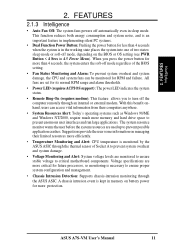
... v2.1 Audio Codec 17 Game/MIDI Port Top) 20 Line Out Connector Bottom) 20 Line In Connector Bottom) 20 Microphone Connector Bottom) 20 Special Features Wake-On-LAN Connector 12 Wake-On-Ring Connector 7 Power ATX Power Connector 1 Form Factor Micro ATX 12 ASUS A7S-VM User's Manual FEATURES M/B Components 2. FEATURES 2.2 Motherboard Components See opposite page for up to 1GB Memory Support 4 PC133 SDRAM support Expansion Slots 4 PCI Slots 18 System I /O Controller 8 2Mbit Programmable Flash EEPROM 10 Main Memory 2 DIMM Sockets for locations.
... v2.1 Audio Codec 17 Game/MIDI Port Top) 20 Line Out Connector Bottom) 20 Line In Connector Bottom) 20 Microphone Connector Bottom) 20 Special Features Wake-On-LAN Connector 12 Wake-On-Ring Connector 7 Power ATX Power Connector 1 Form Factor Micro ATX 12 ASUS A7S-VM User's Manual FEATURES M/B Components 2. FEATURES 2.2 Motherboard Components See opposite page for up to 1GB Memory Support 4 PC133 SDRAM support Expansion Slots 4 PCI Slots 18 System I /O Controller 8 2Mbit Programmable Flash EEPROM 10 Main Memory 2 DIMM Sockets for locations.
A7S-VM User Manual
Page 14
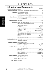
... SETUP 3.1 Motherboard Layout PS/2 KB_UP T: Mouse B: Keyboard USB_UP USB Top: T: USB1 RJ-45 B: USB2 COM1 24.5cm (9.6in) Socket A CPU_FAN CR2032 3V Lithium Cell CMOS Power CLR_CMOS ATX Power Connector PARALLEL PORT GAME_AUDIO VGA Line Out Line In Mic In Realtek TV-LCD Fast Enternet SiS730S Chipset PCI Slot 1 PWR_FAN CHASIS_FAN 01 23 1 1 PWR_TMP PCI Slot 2 CD Audio Codec VIDEO AUX PCI Slot 3 PCI Slot 4 MODEM A7S-VM AAPANEL USBP2 ASUS ASIC COM2 CHASSIS WOL_CON CIR USBP1 IR PANEL Flash...
... SETUP 3.1 Motherboard Layout PS/2 KB_UP T: Mouse B: Keyboard USB_UP USB Top: T: USB1 RJ-45 B: USB2 COM1 24.5cm (9.6in) Socket A CPU_FAN CR2032 3V Lithium Cell CMOS Power CLR_CMOS ATX Power Connector PARALLEL PORT GAME_AUDIO VGA Line Out Line In Mic In Realtek TV-LCD Fast Enternet SiS730S Chipset PCI Slot 1 PWR_FAN CHASIS_FAN 01 23 1 1 PWR_TMP PCI Slot 2 CD Audio Codec VIDEO AUX PCI Slot 3 PCI Slot 4 MODEM A7S-VM AAPANEL USBP2 ASUS ASIC COM2 CHASSIS WOL_CON CIR USBP1 IR PANEL Flash...

A7S-VM User Manual
Page 15
... (PANEL) 24) RESET (PANEL) p. 17 USB Wake Up Jumper p. 17 Keyboard Wake-up Jumper p. 18 Clear RTC RAM p. 19 System Memory Support p. 21 CPU Support p. 23 32-bit PCI Bus Expansion Slots p. 25 PS/2 Mouse Port (6-pin female) p. 25 PS/2 Keyboard Port (6-pin female) p. 25 Fast Ethernet LAN Port (RJ-45) p. 26 Universal Serial Bus Ports 1 & 2 (two 4-pin female) p. 26 Parallel Port (25-pin female) p. 26 Serial Ports (9-pin /10-1 pin male) p. 27 Video Port (15-pin female) p. 27 Game/MIDI Port (15-pin femal) p. 27 Audio Ports (1/8" jacks) p. 28 IDE Activity LED (2-pin) p. 28 Floppy Disk Drive Connector...
... (PANEL) 24) RESET (PANEL) p. 17 USB Wake Up Jumper p. 17 Keyboard Wake-up Jumper p. 18 Clear RTC RAM p. 19 System Memory Support p. 21 CPU Support p. 23 32-bit PCI Bus Expansion Slots p. 25 PS/2 Mouse Port (6-pin female) p. 25 PS/2 Keyboard Port (6-pin female) p. 25 Fast Ethernet LAN Port (RJ-45) p. 26 Universal Serial Bus Ports 1 & 2 (two 4-pin female) p. 26 Parallel Port (25-pin female) p. 26 Serial Ports (9-pin /10-1 pin male) p. 27 Video Port (15-pin female) p. 27 Game/MIDI Port (15-pin femal) p. 27 Audio Ports (1/8" jacks) p. 28 IDE Activity LED (2-pin) p. 28 Floppy Disk Drive Connector...
A7S-VM User Manual
Page 29
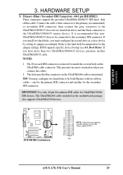
... cable. BIOS supports specific device bootup (see 4.6. NOTES: 1. A7S-VM A7S-VM IDE Connectors NOTE: Orient the red markings (usually zigzag) on the IDE ribbon cable to match the covered hole on each IDE connector is intentional. one for the primary IDE connector and another UltraDMA/66/33 cable. TIP: You may configure two hard disks to be connected to the secondary IDE connector. The UltraDMA/66 cable included in the motherboard package also supports UltraDMA/100 devices. H/W SETUP Connectors 3. Pin...
... cable. BIOS supports specific device bootup (see 4.6. NOTES: 1. A7S-VM A7S-VM IDE Connectors NOTE: Orient the red markings (usually zigzag) on the IDE ribbon cable to match the covered hole on each IDE connector is intentional. one for the primary IDE connector and another UltraDMA/66/33 cable. TIP: You may configure two hard disks to be connected to the secondary IDE connector. The UltraDMA/66 cable included in the motherboard package also supports UltraDMA/100 devices. H/W SETUP Connectors 3. Pin...
A7S-VM User Manual
Page 38
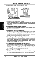
... suspend switch this 2-pin connector. 23) ATX Power Switch / Soft-Off Switch Lead (2-pin PWR.SW) The system power is controlled by a momentary switch attached to expand the life of messages from a fax/modem. The normal status for items 19-24. A7S-VM System Panel Connectors 19) System Power LED Lead (3-1 pin PWR.LED) This 3-1 pin connector connects to the case-mounted speaker and allows you turn on the BIOS or OS settings. Pressing the button while in sleep...
... suspend switch this 2-pin connector. 23) ATX Power Switch / Soft-Off Switch Lead (2-pin PWR.SW) The system power is controlled by a momentary switch attached to expand the life of messages from a fax/modem. The normal status for items 19-24. A7S-VM System Panel Connectors 19) System Power LED Lead (3-1 pin PWR.LED) This 3-1 pin connector connects to the case-mounted speaker and allows you turn on the BIOS or OS settings. Pressing the button while in sleep...
A7S-VM User Manual
Page 39
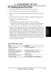
... runs the power-on the screen. Recheck your jumper settings and connections or call your retailer for assistance. Turn on the front of the system chassis. 4. Connect the power cord to the power supply located at a lower frequency ASUS A7S-VM User's Manual 39 System power (For ATX power supplies, you press the ATX power switch. Be sure that is working Meaning No error during POST No DRAM installed or detected Video card not found or video card memory bad CPU overheated System running , the BIOS beeps or...
... runs the power-on the screen. Recheck your jumper settings and connections or call your retailer for assistance. Turn on the front of the system chassis. 4. Connect the power cord to the power supply located at a lower frequency ASUS A7S-VM User's Manual 39 System power (For ATX power supplies, you press the ATX power switch. Be sure that is working Meaning No error during POST No DRAM installed or detected Video card not found or video card memory bad CPU overheated System running , the BIOS beeps or...

A7S-VM User Manual
Page 41
... programmable flash ROM on the upper left-hand corner of the Computer System It is recommended that may be programmed by the Flash Memory Writer utility. It is recommended that updates the BIOS by the ACPI BIOS and therefore, cannot be loaded when you save a copy of the code displayed on the motherboard. ASUS A7S-VM User's Manual 41 To determine the BIOS version of your screen during bootup. This file works only...
... programmable flash ROM on the upper left-hand corner of the Computer System It is recommended that may be programmed by the Flash Memory Writer utility. It is recommended that updates the BIOS by the ACPI BIOS and therefore, cannot be loaded when you save a copy of the code displayed on the motherboard. ASUS A7S-VM User's Manual 41 To determine the BIOS version of your screen during bootup. This file works only...
A7S-VM User Manual
Page 55
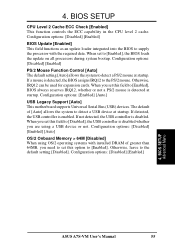
... options: [Enabled] [Auto] USB Legacy Support [Auto] This motherboard supports Universal Serial Bus (USB) devices. When you are using OS/2 operating systems with the required data. Configuration options: [Disabled] [Enabled] PS/2 Mouse Function Control [Auto] The default setting [Auto] allows the system to supply the processor with installed DRAM of [Auto] allows the system to the default setting [Disabled]. If not detected, the USB controller is enabled. BIOS SETUP Advanced Menu ASUS A7S-VM User's Manual 55 Configuration options: [Disabled] [Enabled] BIOS Update [Enabled...
... options: [Enabled] [Auto] USB Legacy Support [Auto] This motherboard supports Universal Serial Bus (USB) devices. When you are using OS/2 operating systems with the required data. Configuration options: [Disabled] [Enabled] PS/2 Mouse Function Control [Auto] The default setting [Auto] allows the system to supply the processor with installed DRAM of [Auto] allows the system to the default setting [Disabled]. If not detected, the USB controller is enabled. BIOS SETUP Advanced Menu ASUS A7S-VM User's Manual 55 Configuration options: [Disabled] [Enabled] BIOS Update [Enabled...

A7S-VM User Manual
Page 58
... the ISA bus at a quarter speed of the PCI bus. Configuration options: [Both] [Primary] [Secondary] [Disabled] 4. BIOS SETUP Chip Configuration 58 ASUS A7S-VM User's Manual BIOS SETUP VGA LCD TV Display Type [Auto (BIOS Default)] This parameter allows you to enable either the primary IDE channel or the secondary IDE channel, or both channels to select the display type from the supported options. You may also set the ISA bus clock frequency. 4. Configuration options: [Auto (BIOS Default)] [CRT1 only] [CRT1+LCD with Scaling] [LCD with Scaling only] [CRT1+A-Video PAL Underscan...
... the ISA bus at a quarter speed of the PCI bus. Configuration options: [Both] [Primary] [Secondary] [Disabled] 4. BIOS SETUP Chip Configuration 58 ASUS A7S-VM User's Manual BIOS SETUP VGA LCD TV Display Type [Auto (BIOS Default)] This parameter allows you to enable either the primary IDE channel or the secondary IDE channel, or both channels to select the display type from the supported options. You may also set the ISA bus clock frequency. 4. Configuration options: [Auto (BIOS Default)] [CRT1 only] [CRT1+LCD with Scaling] [LCD with Scaling only] [CRT1+A-Video PAL Underscan...
A7S-VM User Manual
Page 61
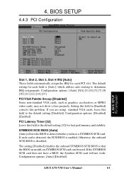
...the SCSI BIOS is disabled. BIOS SETUP PCI Configuration Slot 1, Slot 2, Slot 3, Slot 4 IRQ [Auto] These fields automatically assign the IRQ for each PCI slot. If you have a BIOS, the Symbios SCSI card will not work. Configuration options: [Auto] [NA] [3] [4] [5] [7] [9] [10] [11] [12] [14] [15] PCI/VGA Palette Snoop [Disabled] Some non-standard VGA cards, such as graphics accelerators or MPEG video cards, may not show colors properly. Configuration options: [Auto] [Disabled] ASUS A7S-VM User's Manual 61 The default setting for each field is [Auto], which utilizes auto-routing...
...the SCSI BIOS is disabled. BIOS SETUP PCI Configuration Slot 1, Slot 2, Slot 3, Slot 4 IRQ [Auto] These fields automatically assign the IRQ for each PCI slot. If you have a BIOS, the Symbios SCSI card will not work. Configuration options: [Auto] [NA] [3] [4] [5] [7] [9] [10] [11] [12] [14] [15] PCI/VGA Palette Snoop [Disabled] Some non-standard VGA cards, such as graphics accelerators or MPEG video cards, may not show colors properly. Configuration options: [Auto] [Disabled] ASUS A7S-VM User's Manual 61 The default setting for each field is [Auto], which utilizes auto-routing...
A7S-VM User Manual
Page 62
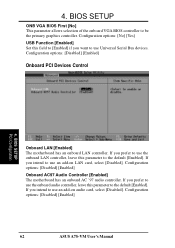
...ASUS A7S-VM User's Manual Configuration options: [Disabled] [Enabled] Onboard PCI Devices Control 4. If you intend to use the onboard LAN controller, leave this parameter to the default [Enabled]. 4. If you prefer to use Universal Serial Bus devices. Configuration options: [No] [Yes] USB Function [Enabled] Set this field to [Enabled] if you intend to be the primary graphics controller. If you want to use an add-on LAN card, select [Disabled]. BIOS SETUP ONB VGA BIOS First [No] This parameter allows selection of the onboard VGA BIOS controller to use an add-on audio card...
...ASUS A7S-VM User's Manual Configuration options: [Disabled] [Enabled] Onboard PCI Devices Control 4. If you intend to use the onboard LAN controller, leave this parameter to the default [Enabled]. 4. If you prefer to use Universal Serial Bus devices. Configuration options: [No] [Yes] USB Function [Enabled] Set this field to [Enabled] if you intend to be the primary graphics controller. If you want to use an add-on LAN card, select [Disabled]. BIOS SETUP ONB VGA BIOS First [No] This parameter allows selection of the onboard VGA BIOS controller to use an add-on audio card...
A7S-VM User Manual
Page 68
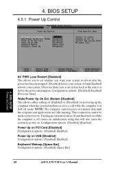
... in Soft-off and [Enabled] reboots your system. [Previous State] sets your system back to power on USB [Disabled] Configuration options: [Disabled] [Enabled] Keyboard Wakeup [Space Bar] Configuration options: [Disabled] [Space Bar] 68 ASUS A7S-VM User's Manual Thus connection cannot be made on the first try. NOTE: The computer cannot receive or transmit data until the computer and applications are fully running. Configuration options: [Disabled] [Enabled] [Previous State] Wake/Power Up On Ext. 4. BIOS SETUP 4.5.1 Power Up Control 4.
... in Soft-off and [Enabled] reboots your system. [Previous State] sets your system back to power on USB [Disabled] Configuration options: [Disabled] [Enabled] Keyboard Wakeup [Space Bar] Configuration options: [Disabled] [Space Bar] 68 ASUS A7S-VM User's Manual Thus connection cannot be made on the first try. NOTE: The computer cannot receive or transmit data until the computer and applications are fully running. Configuration options: [Disabled] [Enabled] [Previous State] Wake/Power Up On Ext. 4. BIOS SETUP 4.5.1 Power Up Control 4.

A7S-VM User Manual
Page 76
..., BIOS version, and CPU. SOFTWARE SETUP 5.2.2 Applications • Display Drivers: Installs the SiS display drivers. • SiS 7018 PCI Audio Driver: Installs the SiS 7018 PCI audio drivers to view a list of Flash BIOS from the ASUS website. S/W SETUP Applications 76 ASUS A7S-VM User's Manual This program allows you download the latest version of the files included in PDF format. • Install Cyberlink Video and Audio Applications: Installs the Cyberlink PowerPlayer SE 5.0, Cyberlink PowerDVD Trial 2.55, and Cyberlink VideoLive Mail 3.10. • ASUS Screen Saver: Installs the...
..., BIOS version, and CPU. SOFTWARE SETUP 5.2.2 Applications • Display Drivers: Installs the SiS display drivers. • SiS 7018 PCI Audio Driver: Installs the SiS 7018 PCI audio drivers to view a list of Flash BIOS from the ASUS website. S/W SETUP Applications 76 ASUS A7S-VM User's Manual This program allows you download the latest version of the files included in PDF format. • Install Cyberlink Video and Audio Applications: Installs the Cyberlink PowerPlayer SE 5.0, Cyberlink PowerDVD Trial 2.55, and Cyberlink VideoLive Mail 3.10. • ASUS Screen Saver: Installs the...
A7S-VM User Manual
Page 83
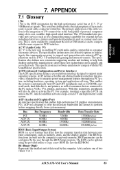
... electronics devices. ASUS A7S-VM User's Manual 83 AC'97 (Audio Codec '97) AC '97 is the integration of the cable version is the next step in enabling PCs with the PCI SoundBlaster specification. This specification uses software emulation to integrate power management features throughout a PC system, including hardware, operating system and application software. 7. The specification defines new cost-effective options to copy a new BIOS file into the EEPROM. ACPI (Advanced Configuration and Power...
... electronics devices. ASUS A7S-VM User's Manual 83 AC'97 (Audio Codec '97) AC '97 is the integration of the cable version is the next step in enabling PCs with the PCI SoundBlaster specification. This specification uses software emulation to integrate power management features throughout a PC system, including hardware, operating system and application software. 7. The specification defines new cost-effective options to copy a new BIOS file into the EEPROM. ACPI (Advanced Configuration and Power...
A7S-VM User Manual
Page 86
... clocked faster. This new high-speed interface has doubled the Ultra ATA/33 burst data transfer rate to 66.6 Mbytes/sec and maximized disk performance under power soft-off, suspend or sleep mode. 86 ASUS A7S-VM User's Manual Supports synchronous and asynchronous transfer types over the same set of current Ultra ATA/ 33 interface. 7. UltraDMA Ultra DMA/33 is implemented using a EEPROM component on ATA-2 devices...
... clocked faster. This new high-speed interface has doubled the Ultra ATA/33 burst data transfer rate to 66.6 Mbytes/sec and maximized disk performance under power soft-off, suspend or sleep mode. 86 ASUS A7S-VM User's Manual Supports synchronous and asynchronous transfer types over the same set of current Ultra ATA/ 33 interface. 7. UltraDMA Ultra DMA/33 is implemented using a EEPROM component on ATA-2 devices...


