A7S-VM User Manual
Page 2
... OF MERCHANTABILITY OR FITNESS FOR A PARTICULAR PURPOSE. Manual updates are trademarks of the means indicated on the product itself. Product Name: ASUS A7S-VM Manual Revision: 1.03 E762 Release Date: April 2001 2 ASUS A7S-VM User's Manual Products and corporate names appearing in this manual, including the products and software described in any form or by...
... OF MERCHANTABILITY OR FITNESS FOR A PARTICULAR PURPOSE. Manual updates are trademarks of the means indicated on the product itself. Product Name: ASUS A7S-VM Manual Revision: 1.03 E762 Release Date: April 2001 2 ASUS A7S-VM User's Manual Products and corporate names appearing in this manual, including the products and software described in any form or by...
A7S-VM User Manual
Page 3
...) Notebook (Tel): +886-2-2890-7122 (English) Desktop/Server (Tel):+886-2-2890-7123 (English) Fax: +886-2-2893-7775 Email: tsd@asus.com.tw WWW: www.asus.com.tw FTP: ftp.asus.com.tw/pub/ASUS ASUS COMPUTER INTERNATIONAL (America) Marketing Address: 6737 Mowry Avenue, Mowry Business Center, Building 2 Newark, CA 94560, USA Fax: +1-510-608-4555... Fax: +49-2102-9599-11 Support (Email): www.asuscom.de/de/support (for online support) WWW: www.asuscom.de FTP: ftp.asuscom.de/pub/ASUSCOM ASUS A7S-VM User's Manual 3
...) Notebook (Tel): +886-2-2890-7122 (English) Desktop/Server (Tel):+886-2-2890-7123 (English) Fax: +886-2-2893-7775 Email: tsd@asus.com.tw WWW: www.asus.com.tw FTP: ftp.asus.com.tw/pub/ASUS ASUS COMPUTER INTERNATIONAL (America) Marketing Address: 6737 Mowry Avenue, Mowry Business Center, Building 2 Newark, CA 94560, USA Fax: +1-510-608-4555... Fax: +49-2102-9599-11 Support (Email): www.asuscom.de/de/support (for online support) WWW: www.asuscom.de FTP: ftp.asuscom.de/pub/ASUSCOM ASUS A7S-VM User's Manual 3

A7S-VM User Manual
Page 4
... 24 3.8 Connectors 25 3.8.1 External Connectors 25 3.8.2 Internal Connectors 28 3.9 Starting Up the First Time 39 4. INTRODUCTION 7 1.1 How This Manual Is Organized 7 1.2 Item Checklist 7 2. CONTENTS 1. FEATURES 8 2.1 ASUS A7S-VM Motherboard 8 2.1.1 Specifications 8 2.1.2 Performance 10 2.1.3 Intelligence 11 2.2 Motherboard Components 12 2.2.1 Component Locations 13 3. BIOS SETUP 41 4.1 Managing and Updating Your BIOS 41 4.1.1 Upon First Use of...
... 24 3.8 Connectors 25 3.8.1 External Connectors 25 3.8.2 Internal Connectors 28 3.9 Starting Up the First Time 39 4. INTRODUCTION 7 1.1 How This Manual Is Organized 7 1.2 Item Checklist 7 2. CONTENTS 1. FEATURES 8 2.1 ASUS A7S-VM Motherboard 8 2.1.1 Specifications 8 2.1.2 Performance 10 2.1.3 Intelligence 11 2.2 Motherboard Components 12 2.2.1 Component Locations 13 3. BIOS SETUP 41 4.1 Managing and Updating Your BIOS 41 4.1.1 Upon First Use of...
A7S-VM User Manual
Page 5
... 4.4.3 PCI Configuration 61 4.4.4 Shadow Configuration 65 4.5 Power Menu 66 4.5.1 Power Up Control 68 4.5.2 Hardware Monitor 69 4.6 Boot Menu 70 4.7 Exit Menu 72 5. SOFTWARE REFERENCE 77 6.1 ASUS PC Probe 77 7. APPENDIX 83 7.1 Glossary 83 INDEX 87 ASUS A7S-VM User's Manual 5 SOFTWARE SETUP 75 5.1 Operating Systems 75 5.1.1 Windows 98 First Time Installation 75...
... 4.4.3 PCI Configuration 61 4.4.4 Shadow Configuration 65 4.5 Power Menu 66 4.5.1 Power Up Control 68 4.5.2 Hardware Monitor 69 4.6 Boot Menu 70 4.7 Exit Menu 72 5. SOFTWARE REFERENCE 77 6.1 ASUS PC Probe 77 7. APPENDIX 83 7.1 Glossary 83 INDEX 87 ASUS A7S-VM User's Manual 5 SOFTWARE SETUP 75 5.1 Operating Systems 75 5.1.1 Windows 98 First Time Installation 75...
A7S-VM User Manual
Page 6
... the Federal Register, National Archives and Records Administration, U.S. Cet appareil numérique de la classe B est conforme à la norme NMB-003 du Canada. 6 ASUS A7S-VM User's Manual Reprinted from digital apparatus set out in accordance with the limits for help. This Class B digital apparatus complies with FCC Rules Part 15...
... the Federal Register, National Archives and Records Administration, U.S. Cet appareil numérique de la classe B est conforme à la norme NMB-003 du Canada. 6 ASUS A7S-VM User's Manual Reprinted from digital apparatus set out in accordance with the limits for help. This Class B digital apparatus complies with FCC Rules Part 15...

A7S-VM User Manual
Page 7
...and specifications Instructions on LAN models only) (1) User's Manual ASUS A7S-VM User's Manual 7 INTRODUCTION 1.1 How This Manual Is Organized This manual is complete. Package Contents (1) ASUS Motherboard Optional Items ASUS Modem MR (1) 40-pin 80-conductor ribbon cable for internal...on setting up the included software Reference material for two 3.5" floppy disk drives (1) ASUS Support CD with drivers and utilities ASUS IrDA-compliant infrared module (1) Bag of spare jumper caps (1) ASUS 2-port USB Connector Set (1) I/O Plate (on setting up the motherboard. SOFTWARE SETUP...
...and specifications Instructions on LAN models only) (1) User's Manual ASUS A7S-VM User's Manual 7 INTRODUCTION 1.1 How This Manual Is Organized This manual is complete. Package Contents (1) ASUS Motherboard Optional Items ASUS Modem MR (1) 40-pin 80-conductor ribbon cable for internal...on setting up the included software Reference material for two 3.5" floppy disk drives (1) ASUS Support CD with drivers and utilities ASUS IrDA-compliant infrared module (1) Bag of spare jumper caps (1) ASUS 2-port USB Connector Set (1) I/O Plate (on setting up the motherboard. SOFTWARE SETUP...

A7S-VM User Manual
Page 8
.../100 Fast Ethernet PCI card. • Wake-On-Ring: Supports Wake-On-Ring activity through the onboard hardware ASUS ASIC and the bundled ASUS PC Probe. 8 ASUS A7S-VM User's Manual UART2 can also be directed from COM2 to 1GB of memory using unbuffered PC133/100-compliant SDRAMs. ... Master IDE controller with Front Side Bus (FSB) frequency of the Socket A-based processor. FEATURES 2.1 ASUS A7S-VM Motherboard Powered by AMD Athlon / AMD Duron processors, the ASUS A7S-VM motherboard bundles advanced technology to support two high-speed UART compatible serial ports and one parallel port with...
.../100 Fast Ethernet PCI card. • Wake-On-Ring: Supports Wake-On-Ring activity through the onboard hardware ASUS ASIC and the bundled ASUS PC Probe. 8 ASUS A7S-VM User's Manual UART2 can also be directed from COM2 to 1GB of memory using unbuffered PC133/100-compliant SDRAMs. ... Master IDE controller with Front Side Bus (FSB) frequency of the Socket A-based processor. FEATURES 2.1 ASUS A7S-VM Motherboard Powered by AMD Athlon / AMD Duron processors, the ASUS A7S-VM motherboard bundles advanced technology to support two high-speed UART compatible serial ports and one parallel port with...

A7S-VM User Manual
Page 9
... 2. The AFPANEL connector on -chip sample rate converter, and a professional wavetable. • Connectivity Interface: Supports an optional ASUS iPanel, an easy-to communicate within a standard protocol and create a higher level of most devices for Windows 98 compatibility, ...audio and modem features that comprise digital audio engine with system diagnostic display area, system status LEDs, USB ports, and hot keys. ASUS A7S-VM User's Manual 9 FEATURES • SMBus: Features the System Management Bus interface used to physically transport commands and information between SMBus devices....
... 2. The AFPANEL connector on -chip sample rate converter, and a professional wavetable. • Connectivity Interface: Supports an optional ASUS iPanel, an easy-to communicate within a standard protocol and create a higher level of most devices for Windows 98 compatibility, ...audio and modem features that comprise digital audio engine with system diagnostic display area, system status LEDs, USB ports, and hot keys. ASUS A7S-VM User's Manual 9 FEATURES • SMBus: Features the System Management Bus interface used to physically transport commands and information between SMBus devices....

A7S-VM User Manual
Page 10
... 80-conductor cable). • Concurrent PCI: Concurrent PCI allows multiple PCI transfers from PCI master busses to the memory and processor. 10 ASUS A7S-VM User's Manual Color-coded connectors and descriptive icons make identification easy as Windows 98/2000/Millenium. • PC'99 Compliant: Both the ...BIOS and hardware levels of ASUS smart series motherboards are based on the following high-level goals: Support for Plugn-Play compatibility and power management for configuring and ...
... 80-conductor cable). • Concurrent PCI: Concurrent PCI allows multiple PCI transfers from PCI master busses to the memory and processor. 10 ASUS A7S-VM User's Manual Color-coded connectors and descriptive icons make identification easy as Windows 98/2000/Millenium. • PC'99 Compliant: Both the ...BIOS and hardware levels of ASUS smart series motherboards are based on the following high-level goals: Support for Plugn-Play compatibility and power management for configuring and ...
A7S-VM User Manual
Page 11
... Ring-On (requires modem): This feature allows you press the power button for future processors, so monitoring is monitored by the ASUS ASIC through the ASUS ASIC. All fans are more critical for more than 4 seconds when the system is in the working state places the system ...and system damage. • Voltage Monitoring and Alert: System voltage levels are used up to present enormous user interfaces and run large applications. ASUS A7S-VM User's Manual 11 A chassis intrusion event is an important feature in implementing silent PC systems. • Dual Function Power Button: Pushing ...
... Ring-On (requires modem): This feature allows you press the power button for future processors, so monitoring is monitored by the ASUS ASIC through the ASUS ASIC. All fans are more critical for more than 4 seconds when the system is in the working state places the system ...and system damage. • Voltage Monitoring and Alert: System voltage levels are used up to present enormous user interfaces and run large applications. ASUS A7S-VM User's Manual 11 A chassis intrusion event is an important feature in implementing silent PC systems. • Dual Function Power Button: Pushing ...
A7S-VM User Manual
Page 12
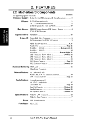
...SDRAM support Expansion Slots 4 PCI Slots 18 System I/O Floppy Disk Drive Connector 6 IDE Connectors (UltraDMA/100 Support 5 ASUS iPanel Connectors 9, 16 Parallel Port Top) 21 Serial Port 1 (COM1 Bottom Left) 21 Serial Port 2 (COM2 14...11 USB Connectors (Port 4 & Port 5 13 PS/2 Mouse Connector Top) 23 PS/2 Keyboard Connector Bottom) 23 Hardware Monitoring ASUS ASIC 15 3 Fan Power Connectors Network Features (on LAN models only) RealTek RTL8100 Fast Ethernet Controller 19 LAN Connector (RJ-45 ...Power ATX Power Connector 1 Form Factor Micro ATX 12 ASUS A7S-VM User's Manual 2.
...SDRAM support Expansion Slots 4 PCI Slots 18 System I/O Floppy Disk Drive Connector 6 IDE Connectors (UltraDMA/100 Support 5 ASUS iPanel Connectors 9, 16 Parallel Port Top) 21 Serial Port 1 (COM1 Bottom Left) 21 Serial Port 2 (COM2 14...11 USB Connectors (Port 4 & Port 5 13 PS/2 Mouse Connector Top) 23 PS/2 Keyboard Connector Bottom) 23 Hardware Monitoring ASUS ASIC 15 3 Fan Power Connectors Network Features (on LAN models only) RealTek RTL8100 Fast Ethernet Controller 19 LAN Connector (RJ-45 ...Power ATX Power Connector 1 Form Factor Micro ATX 12 ASUS A7S-VM User's Manual 2.
A7S-VM User Manual
Page 14
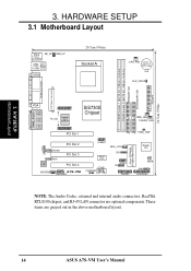
... Chipset PCI Slot 1 PWR_FAN CHASIS_FAN 01 23 1 1 PWR_TMP PCI Slot 2 CD Audio Codec VIDEO AUX PCI Slot 3 PCI Slot 4 MODEM A7S-VM AAPANEL USBP2 ASUS ASIC COM2 CHASSIS WOL_CON CIR USBP1 IR PANEL Flash EEPROM (Programable BIOS) Super I/O WOR SMB AFPANEL NOTE: The Audio Codec, external and internal... audio connectors, RealTek RTL8100 chipset, and RJ-45 LAN connector are grayed out in the above motherboard layout. 14 ASUS A7S-VM User's Manual DIMM Socket 1 (64/72-bit, 168-pin module) DIMM Socket 2 (64/72-bit, 168-pin module) PRIMARY IDE SECONDARY...
... Chipset PCI Slot 1 PWR_FAN CHASIS_FAN 01 23 1 1 PWR_TMP PCI Slot 2 CD Audio Codec VIDEO AUX PCI Slot 3 PCI Slot 4 MODEM A7S-VM AAPANEL USBP2 ASUS ASIC COM2 CHASSIS WOL_CON CIR USBP1 IR PANEL Flash EEPROM (Programable BIOS) Super I/O WOR SMB AFPANEL NOTE: The Audio Codec, external and internal... audio connectors, RealTek RTL8100 chipset, and RJ-45 LAN connector are grayed out in the above motherboard layout. 14 ASUS A7S-VM User's Manual DIMM Socket 1 (64/72-bit, 168-pin module) DIMM Socket 2 (64/72-bit, 168-pin module) PRIMARY IDE SECONDARY...

A7S-VM User Manual
Page 15
... Fan Connectors (3-pin) p. 32 Chassis Intrusion Lead (4-1 pin) p. 32 SMBus Connector (5-1 pin) p. 33 Standard Infrared Module Connector (5-pin) p. 33 Consumer Infrared Module Connector (5-pin) p. 34 ASUS iPanel Connector (12-1 pin) p. 34 Audio Panel Connector (12-1 pin) p. 35 USB Headers (two 10-1 pin) p. 35 Internal Audio Connectors (4-1 pin) p. 36 LCD Headers (two... (4-pin) p. 38 System Message LED Lead (2-pin) p. 38 System Management Interrupt Lead (2-pin) p. 38 ATX / Soft-Off Switch Lead (2-pin) p. 38 Reset Switch Lead (2-pin) ASUS A7S-VM User's Manual 15
... Fan Connectors (3-pin) p. 32 Chassis Intrusion Lead (4-1 pin) p. 32 SMBus Connector (5-1 pin) p. 33 Standard Infrared Module Connector (5-pin) p. 33 Consumer Infrared Module Connector (5-pin) p. 34 ASUS iPanel Connector (12-1 pin) p. 34 Audio Panel Connector (12-1 pin) p. 35 USB Headers (two 10-1 pin) p. 35 Internal Audio Connectors (4-1 pin) p. 36 LCD Headers (two... (4-pin) p. 38 System Message LED Lead (2-pin) p. 38 System Management Interrupt Lead (2-pin) p. 38 ATX / Soft-Off Switch Lead (2-pin) p. 38 Reset Switch Lead (2-pin) ASUS A7S-VM User's Manual 15
A7S-VM User Manual
Page 16
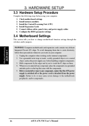
... parameter settings 3.4 Motherboard Settings This section tells you install or remove any component, place the components on the internal components. 2. WARNING! H/W SETUP Motherboard Settings 16 ASUS A7S-VM User's Manual HARDWARE SETUP 3.3 Hardware Setup Procedure Complete the following steps before handling computer components. 3. Connect ribbon cables, panel wires, and power supply cables 6. Install...
... parameter settings 3.4 Motherboard Settings This section tells you install or remove any component, place the components on the internal components. 2. WARNING! H/W SETUP Motherboard Settings 16 ASUS A7S-VM User's Manual HARDWARE SETUP 3.3 Hardware Setup Procedure Complete the following steps before handling computer components. 3. Connect ribbon cables, panel wires, and power supply cables 6. Install...

A7S-VM User Manual
Page 17
... total current consumed must NOT exceed the power supply capability (+5VSB) whether under normal working conditions or in sleep mode. A7S-VM A7S-VM Keyboard Wake Up KB_UP 2 1 Disable (Default) 3 2 Enable ASUS A7S-VM User's Manual 17 A7S-VM A7S-VM USB Wake Up USB_UP 2 1 Disable (Default) 3 2 Enable 2) Keyboard Wake-up Jumper (3-pin KB_UP) This jumper allows you to wake up...
... total current consumed must NOT exceed the power supply capability (+5VSB) whether under normal working conditions or in sleep mode. A7S-VM A7S-VM Keyboard Wake Up KB_UP 2 1 Disable (Default) 3 2 Enable ASUS A7S-VM User's Manual 17 A7S-VM A7S-VM USB Wake Up USB_UP 2 1 Disable (Default) 3 2 Enable 2) Keyboard Wake-up Jumper (3-pin KB_UP) This jumper allows you to wake up...
A7S-VM User Manual
Page 18
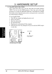
... RAM data. The RAM data in CMOS. Short the solder points. 4. H/W SETUP Motherboard Settings 18 ASUS A7S-VM User's Manual Re-install the battery. 5. HARDWARE SETUP 3) Clear RTC RAM (CLR_CMOS) These solder points allow you to Clear CMOS A7S-VM A7S-VM Clear RTC RAM 3. You can clear the CMOS memory of date, time, and system setup...
... RAM data. The RAM data in CMOS. Short the solder points. 4. H/W SETUP Motherboard Settings 18 ASUS A7S-VM User's Manual Re-install the battery. 5. HARDWARE SETUP 3) Clear RTC RAM (CLR_CMOS) These solder points allow you to Clear CMOS A7S-VM A7S-VM Clear RTC RAM 3. You can clear the CMOS memory of date, time, and system setup...

A7S-VM User Manual
Page 19
... 64,128, 256MB; 3. One side (with higher pin density than 18 chips are not supported on the motherboard. compliant DIMMs. • ASUS motherboards support Serial Presence Detect (SPD) DIMMs. This is the memory of 32MB up one row on this motherboard. • For the system...can handle the specified SDRAM speeds, otherwise the computer will not boot. 3. Install memory in 32, 64, 128, 256, 512MB. H/W SETUP System Memory ASUS A7S-VM User's Manual 19 double-sided come in any combination as follows: DIMM Location Socket 1 (Rows 0&1) Socket 2 (Rows 2&3) 168-pin DIMM SDRAM 16, ...
... 64,128, 256MB; 3. One side (with higher pin density than 18 chips are not supported on the motherboard. compliant DIMMs. • ASUS motherboards support Serial Presence Detect (SPD) DIMMs. This is the memory of 32MB up one row on this motherboard. • For the system...can handle the specified SDRAM speeds, otherwise the computer will not boot. 3. Install memory in 32, 64, 128, 256, 512MB. H/W SETUP System Memory ASUS A7S-VM User's Manual 19 double-sided come in any combination as follows: DIMM Location Socket 1 (Rows 0&1) Socket 2 (Rows 2&3) 168-pin DIMM SDRAM 16, ...

A7S-VM User Manual
Page 20
...-Pin DIMM Sockets Lock The DIMMs must tell your retailer the correct DIMM type before purchasing. This motherboard supports four clock signals per DIMM. 20 ASUS A7S-VM User's Manual HARDWARE SETUP 3.5.2 Memory Installation WARNING! 3. Make sure that you unplug the power supply when adding or removing memory modules or other system components...
...-Pin DIMM Sockets Lock The DIMMs must tell your retailer the correct DIMM type before purchasing. This motherboard supports four clock signals per DIMM. 20 ASUS A7S-VM User's Manual HARDWARE SETUP 3.5.2 Memory Installation WARNING! 3. Make sure that you unplug the power supply when adding or removing memory modules or other system components...
A7S-VM User Manual
Page 21
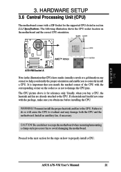
... one corner) to help you identify the proper orientation and enable you to damage the CPU pins. BLANK LEVER LOCK AMD™ Athlon NOTCH A7S-VM A7S-VM Socket A Note in section 2.1.1 Specifications. It is for the steps on the motherboard and the correct CPU orientation. WARNING! Be careful not... corner on one before installing the CPU. Failure to do so will cause the CPU to the CPU. Proceed to properly install a CPU. ASUS A7S-VM User's Manual 21 H/W SETUP CPU 3. You must install the proper heatsink and fan to overheat and may damage both the CPU and the ...
... one corner) to help you identify the proper orientation and enable you to damage the CPU pins. BLANK LEVER LOCK AMD™ Athlon NOTCH A7S-VM A7S-VM Socket A Note in section 2.1.1 Specifications. It is for the steps on the motherboard and the correct CPU orientation. WARNING! Be careful not... corner on one before installing the CPU. Failure to do so will cause the CPU to the CPU. Proceed to properly install a CPU. ASUS A7S-VM User's Manual 21 H/W SETUP CPU 3. You must install the proper heatsink and fan to overheat and may damage both the CPU and the ...

A7S-VM User Manual
Page 22
... sure that it firmly on the socket indicating that the CPU is available only on the motherboard. 2. Refer to install a CPU. 1. H/W SETUP CPU Installation 22 ASUS A7S-VM User's Manual
... sure that it firmly on the socket indicating that the CPU is available only on the motherboard. 2. Refer to install a CPU. 1. H/W SETUP CPU Installation 22 ASUS A7S-VM User's Manual


