
Motherboard DIY Troubleshooting Guide
Page 85
LEDs RJ45 LAN Activity Output Signal Intel Chipset Wake on LAN Output Signal ASUS Motherboard type Other
LEDs RJ45 LAN Activity Output Signal Intel Chipset Wake on LAN Output Signal ASUS Motherboard type Other

A7S-VM User Manual
Page 1
® A7S-VM SiS730S Ultra-AGP Socket A Motherboard USER'S MANUAL
® A7S-VM SiS730S Ultra-AGP Socket A Motherboard USER'S MANUAL

A7S-VM User Manual
Page 4
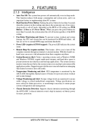
FEATURES 8 2.1 ASUS A7S-VM Motherboard 8 2.1.1 Specifications 8 2.1.2 Performance 10 2.1.3 Intelligence 11 2.2 Motherboard Components 12 2.2.1 Component Locations 13 3. INTRODUCTION 7 1.1 How This Manual Is Organized 7 1.2 Item Checklist 7 2. HARDWARE SETUP 14 3.1 Motherboard Layout 14 3.2 Layout Contents 15 3.3 Hardware Setup Procedure 16 3.4 Motherboard Settings 16 3.5 System Memory 19 3.5.1 General DIMM Notes 19 3.5.2 Memory Installation... Updating BIOS Procedures 43 4.2 BIOS Setup Program 45 4.2.1 BIOS Menu Bar 46 4.2.2 Legend Bar 46 4 ASUS A7S-VM User's Manual
FEATURES 8 2.1 ASUS A7S-VM Motherboard 8 2.1.1 Specifications 8 2.1.2 Performance 10 2.1.3 Intelligence 11 2.2 Motherboard Components 12 2.2.1 Component Locations 13 3. INTRODUCTION 7 1.1 How This Manual Is Organized 7 1.2 Item Checklist 7 2. HARDWARE SETUP 14 3.1 Motherboard Layout 14 3.2 Layout Contents 15 3.3 Hardware Setup Procedure 16 3.4 Motherboard Settings 16 3.5 System Memory 19 3.5.1 General DIMM Notes 19 3.5.2 Memory Installation... Updating BIOS Procedures 43 4.2 BIOS Setup Program 45 4.2.1 BIOS Menu Bar 46 4.2.2 Legend Bar 46 4 ASUS A7S-VM User's Manual
A7S-VM User Manual
Page 5
APPENDIX 83 7.1 Glossary 83 INDEX 87 ASUS A7S-VM User's Manual 5 SOFTWARE REFERENCE 77 6.1 ASUS PC Probe 77 7. SOFTWARE SETUP 75 5.1 Operating Systems 75 5.1.1 Windows 98 First Time Installation 75 5.2 A7S-VM Motherboard Support CD 75 5.2.1 Installation Menus 75 6. CONTENTS 4.3 Main Menu 48 4.3.1 Primary & Secondary Master/Slave 49 4.3.2 Keyboard Features 52 4.4 Advanced Menu 54 4.4.1 Chip Configuration 56 4.4.2 I/O Device...
APPENDIX 83 7.1 Glossary 83 INDEX 87 ASUS A7S-VM User's Manual 5 SOFTWARE REFERENCE 77 6.1 ASUS PC Probe 77 7. SOFTWARE SETUP 75 5.1 Operating Systems 75 5.1.1 Windows 98 First Time Installation 75 5.2 A7S-VM Motherboard Support CD 75 5.2.1 Installation Menus 75 6. CONTENTS 4.3 Main Menu 48 4.3.1 Primary & Secondary Master/Slave 49 4.3.2 Keyboard Features 52 4.4 Advanced Menu 54 4.4.1 Chip Configuration 56 4.4.2 I/O Device...

A7S-VM User Manual
Page 7
Instructions on setting up the BIOS Instructions on LAN models only) (1) User's Manual ASUS A7S-VM User's Manual 7 Package Contents (1) ASUS Motherboard Optional Items ASUS Modem MR (1) 40-pin 80-conductor ribbon cable for internal UltraDMA/ 100/66 or ... software Reference material for two 3.5" floppy disk drives (1) ASUS Support CD with drivers and utilities ASUS IrDA-compliant infrared module (1) Bag of spare jumper caps (1) ASUS 2-port USB Connector Set (1) I/O Plate (on setting up the motherboard. INTRODUCTION Manual / Checklist 1. 1. INTRODUCTION 1.1 How This...
Instructions on setting up the BIOS Instructions on LAN models only) (1) User's Manual ASUS A7S-VM User's Manual 7 Package Contents (1) ASUS Motherboard Optional Items ASUS Modem MR (1) 40-pin 80-conductor ribbon cable for internal UltraDMA/ 100/66 or ... software Reference material for two 3.5" floppy disk drives (1) ASUS Support CD with drivers and utilities ASUS IrDA-compliant infrared module (1) Bag of spare jumper caps (1) ASUS 2-port USB Connector Set (1) I/O Plate (on setting up the motherboard. INTRODUCTION Manual / Checklist 1. 1. INTRODUCTION 1.1 How This...

A7S-VM User Manual
Page 8
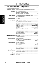
...the JumperFree™ mode is designed with EPP and ECP capabilities. FEATURES Specifications 2. FEATURES 2.1 ASUS A7S-VM Motherboard Powered by AMD Athlon / AMD Duron processors, the ASUS A7S-VM motherboard bundles advanced technology to 1GB of memory using unbuffered PC133/100-compliant SDRAMs. • JumperFree&#...LAN controller that complements the powers of frequency and Vcore voltage through the onboard hardware ASUS ASIC and the bundled ASUS PC Probe. 8 ASUS A7S-VM User's Manual The motherboard is enabled. • UltraDMA/100 Support: Comes with an onboard PCI Bus ...
...the JumperFree™ mode is designed with EPP and ECP capabilities. FEATURES Specifications 2. FEATURES 2.1 ASUS A7S-VM Motherboard Powered by AMD Athlon / AMD Duron processors, the ASUS A7S-VM motherboard bundles advanced technology to 1GB of memory using unbuffered PC133/100-compliant SDRAMs. • JumperFree&#...LAN controller that complements the powers of frequency and Vcore voltage through the onboard hardware ASUS ASIC and the bundled ASUS PC Probe. 8 ASUS A7S-VM User's Manual The motherboard is enabled. • UltraDMA/100 Support: Comes with an onboard PCI Bus ...

A7S-VM User Manual
Page 9
... box with system diagnostic display area, system status LEDs, USB ports, and hot keys. ASUS A7S-VM User's Manual 9 FEATURES Specifications 2. The AFPANEL connector on -chip sample rate converter, and a professional wavetable. •... Connectivity Interface: Supports an optional ASUS iPanel, an easy-to communicate within a standard protocol and create a higher level of compatibility. (Requires DMI-... engine with 3D-hardware accelerator, on the motherboard accommodates the ASUS iPanel.
... box with system diagnostic display area, system status LEDs, USB ports, and hot keys. ASUS A7S-VM User's Manual 9 FEATURES Specifications 2. The AFPANEL connector on -chip sample rate converter, and a professional wavetable. •... Connectivity Interface: Supports an optional ASUS iPanel, an easy-to communicate within a standard protocol and create a higher level of compatibility. (Requires DMI-... engine with 3D-hardware accelerator, on the motherboard accommodates the ASUS iPanel.

A7S-VM User Manual
Page 10
...-coded connectors and descriptive icons make identification easy as Windows 98/2000/Millenium. • PC'99 Compliant: Both the BIOS and hardware levels of ASUS smart series motherboards are based on the following high-level goals: Support for Plugn-Play compatibility and power management for configuring and managing all system components, and... requires a 40-pin 80-conductor cable). • Concurrent PCI: Concurrent PCI allows multiple PCI transfers from PCI master busses to the memory and processor. 10 ASUS A7S-VM User's Manual 2.
...-coded connectors and descriptive icons make identification easy as Windows 98/2000/Millenium. • PC'99 Compliant: Both the BIOS and hardware levels of ASUS smart series motherboards are based on the following high-level goals: Support for Plugn-Play compatibility and power management for configuring and managing all system components, and... requires a 40-pin 80-conductor cable). • Concurrent PCI: Concurrent PCI allows multiple PCI transfers from PCI master busses to the memory and processor. 10 ASUS A7S-VM User's Manual 2.
A7S-VM User Manual
Page 11
With this benefit onhand, users can be monitored for future processors, so monitoring is monitored by the ASUS ASIC through the thermal sensor of Socket A to present enormous user interfaces and run large applications. A chassis intrusion event is...ASUS A7S-VM User's Manual 11 FEATURES 2.1.3 Intelligence • Auto Fan Off: The system fans powers off the computer remotely through the ASUS ASIC. The system resource monitor warns the user before the system resources are more efficiently. • Temperature Monitoring and Alert: CPU temperature is necessary to critical motherboard...
With this benefit onhand, users can be monitored for future processors, so monitoring is monitored by the ASUS ASIC through the thermal sensor of Socket A to present enormous user interfaces and run large applications. A chassis intrusion event is...ASUS A7S-VM User's Manual 11 FEATURES 2.1.3 Intelligence • Auto Fan Off: The system fans powers off the computer remotely through the ASUS ASIC. The system resource monitor warns the user before the system resources are more efficiently. • Temperature Monitoring and Alert: CPU temperature is necessary to critical motherboard...
A7S-VM User Manual
Page 12
...AMD Duron Processors 3 Chipsets SiS730S System Controller 2 iTE IT8705F Super I/O Controller 8 2Mbit Programmable Flash EEPROM 10 Main Memory 2 DIMM Sockets for locations. FEATURES 2.2 Motherboard Components See opposite page for up to 1GB Memory Support 4 PC133 SDRAM support Expansion Slots 4 PCI Slots 18 System I/O Floppy Disk Drive Connector 6 IDE Connectors... Connector Bottom) 20 Special Features Wake-On-LAN Connector 12 Wake-On-Ring Connector 7 Power ATX Power Connector 1 Form Factor Micro ATX 12 ASUS A7S-VM User's Manual FEATURES M/B Components 2. 2.
...AMD Duron Processors 3 Chipsets SiS730S System Controller 2 iTE IT8705F Super I/O Controller 8 2Mbit Programmable Flash EEPROM 10 Main Memory 2 DIMM Sockets for locations. FEATURES 2.2 Motherboard Components See opposite page for up to 1GB Memory Support 4 PC133 SDRAM support Expansion Slots 4 PCI Slots 18 System I/O Floppy Disk Drive Connector 6 IDE Connectors... Connector Bottom) 20 Special Features Wake-On-LAN Connector 12 Wake-On-Ring Connector 7 Power ATX Power Connector 1 Form Factor Micro ATX 12 ASUS A7S-VM User's Manual FEATURES M/B Components 2. 2.
A7S-VM User Manual
Page 14
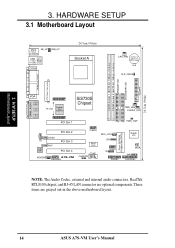
These items are optional components. HARDWARE SETUP 3.1 Motherboard Layout PS/2 KB_UP T: Mouse B: Keyboard USB_UP USB Top: T: USB1 RJ-45 B: USB2 COM1 24.5cm (9.6in) Socket A CPU_FAN CR2032 3V Lithium Cell CMOS Power CLR_CMOS ... AFPANEL NOTE: The Audio Codec, external and internal audio connectors, RealTek RTL8100 chipset, and RJ-45 LAN connector are grayed out in the above motherboard layout. 14 ASUS A7S-VM User's Manual DIMM Socket 1 (64/72-bit, 168-pin module) DIMM Socket 2 (64/72-bit, 168-pin module) PRIMARY IDE SECONDARY IDE FLOPPY 24...
These items are optional components. HARDWARE SETUP 3.1 Motherboard Layout PS/2 KB_UP T: Mouse B: Keyboard USB_UP USB Top: T: USB1 RJ-45 B: USB2 COM1 24.5cm (9.6in) Socket A CPU_FAN CR2032 3V Lithium Cell CMOS Power CLR_CMOS ... AFPANEL NOTE: The Audio Codec, external and internal audio connectors, RealTek RTL8100 chipset, and RJ-45 LAN connector are grayed out in the above motherboard layout. 14 ASUS A7S-VM User's Manual DIMM Socket 1 (64/72-bit, 168-pin module) DIMM Socket 2 (64/72-bit, 168-pin module) PRIMARY IDE SECONDARY IDE FLOPPY 24...

A7S-VM User Manual
Page 15
HARDWARE SETUP 3.2 Layout Contents 3. H/W SETUP Layout Contents Motherboard Settings 1) USB_UP 2) KB_UP 3) CLR_CMOS Expansion Slots/Sockets 1) DIMM 1/2 2) Socket A 3) PCI 1/2/3/4 External Connectors 1) PS2KBMS 2) PS2KBMS 3)...pin) p. 32 SMBus Connector (5-1 pin) p. 33 Standard Infrared Module Connector (5-pin) p. 33 Consumer Infrared Module Connector (5-pin) p. 34 ASUS iPanel Connector (12-1 pin) p. 34 Audio Panel Connector (12-1 pin) p. 35 USB Headers (two 10-1 pin) p. 35 Internal Audio... 38 ATX / Soft-Off Switch Lead (2-pin) p. 38 Reset Switch Lead (2-pin) ASUS A7S-VM User's Manual 15 3.
HARDWARE SETUP 3.2 Layout Contents 3. H/W SETUP Layout Contents Motherboard Settings 1) USB_UP 2) KB_UP 3) CLR_CMOS Expansion Slots/Sockets 1) DIMM 1/2 2) Socket A 3) PCI 1/2/3/4 External Connectors 1) PS2KBMS 2) PS2KBMS 3)...pin) p. 32 SMBus Connector (5-1 pin) p. 33 Standard Infrared Module Connector (5-pin) p. 33 Consumer Infrared Module Connector (5-pin) p. 34 ASUS iPanel Connector (12-1 pin) p. 34 Audio Panel Connector (12-1 pin) p. 35 USB Headers (two 10-1 pin) p. 35 Internal Audio... 38 ATX / Soft-Off Switch Lead (2-pin) p. 38 Reset Switch Lead (2-pin) ASUS A7S-VM User's Manual 15 3.
A7S-VM User Manual
Page 16
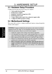
..., panel wires, and power supply cables 6. WARNING! H/W SETUP Motherboard Settings 16 ASUS A7S-VM User's Manual 3. Computer motherboards and expansion cards contain very delicate Integrated Circuit (IC) chips. Unplug the computer when working on them due to static electricity, follow these precautions whenever you how to change motherboard function settings through the switches and/or jumpers...
..., panel wires, and power supply cables 6. WARNING! H/W SETUP Motherboard Settings 16 ASUS A7S-VM User's Manual 3. Computer motherboards and expansion cards contain very delicate Integrated Circuit (IC) chips. Unplug the computer when working on them due to static electricity, follow these precautions whenever you how to change motherboard function settings through the switches and/or jumpers...

A7S-VM User Manual
Page 17
...disable the USB device wake up the computer. HARDWARE SETUP 1) USB Device Wake-up Jumper (3-pin USB_UP) This jumper allows you press the . A7S-VM A7S-VM USB Wake Up USB_UP 2 1 Disable (Default) 3 2 Enable 2) Keyboard Wake-up Jumper (3-pin KB_UP) This jumper allows you have the ...mode. A7S-VM A7S-VM Keyboard Wake Up KB_UP 2 1 Disable (Default) 3 2 Enable ASUS A7S-VM User's Manual 17 Before setting either of this jumper to ENABLE if you wish to use the USB devices to ENABLE, make sure that can supply at least 2A on the +5VSB lead. 3. H/W SETUP Motherboard Settings ...
...disable the USB device wake up the computer. HARDWARE SETUP 1) USB Device Wake-up Jumper (3-pin USB_UP) This jumper allows you press the . A7S-VM A7S-VM USB Wake Up USB_UP 2 1 Disable (Default) 3 2 Enable 2) Keyboard Wake-up Jumper (3-pin KB_UP) This jumper allows you have the ...mode. A7S-VM A7S-VM Keyboard Wake Up KB_UP 2 1 Disable (Default) 3 2 Enable ASUS A7S-VM User's Manual 17 Before setting either of this jumper to ENABLE if you wish to use the USB devices to ENABLE, make sure that can supply at least 2A on the +5VSB lead. 3. H/W SETUP Motherboard Settings ...
A7S-VM User Manual
Page 18
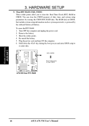
...RAM in CMOS, that include system setup information such as system passwords, is powered by erasing the CMOS RTC RAM data. H/W SETUP Motherboard Settings 18 ASUS A7S-VM User's Manual To erase the RTC RAM: 1. HARDWARE SETUP 3) Clear RTC RAM (CLR_CMOS) These solder points allow you to re-...enter data. Plug the power cord and turn ON the computer. 6. CLR_CMOS Short solder points to Clear CMOS A7S-VM A7S-VM Clear RTC RAM 3. Short the solder...
...RAM in CMOS, that include system setup information such as system passwords, is powered by erasing the CMOS RTC RAM data. H/W SETUP Motherboard Settings 18 ASUS A7S-VM User's Manual To erase the RTC RAM: 1. HARDWARE SETUP 3) Clear RTC RAM (CLR_CMOS) These solder points allow you to re-...enter data. Plug the power cord and turn ON the computer. 6. CLR_CMOS Short solder points to Clear CMOS A7S-VM A7S-VM Clear RTC RAM 3. Short the solder...

A7S-VM User Manual
Page 19
... best performance vs. stability. • SDRAM chips are not supported on this motherboard. • For the system CPU bus to 1GB. WARNING! double-sided come in 16, 32, 64,128, 256MB; H/W SETUP System Memory ASUS A7S-VM User's Manual 19 Install memory in 32, 64, 128, 256, 512MB. ... 1GB) Total Memory x1 x1 = 3.5.1 General DIMM Notes • DIMMs that the DIMM you use only PC100-/PC133- compliant DIMMs. • ASUS motherboards support Serial Presence Detect (SPD) DIMMs. This is the memory of choice for a system memory configuration of the DIMM takes up to operate 100MHz...
... best performance vs. stability. • SDRAM chips are not supported on this motherboard. • For the system CPU bus to 1GB. WARNING! double-sided come in 16, 32, 64,128, 256MB; H/W SETUP System Memory ASUS A7S-VM User's Manual 19 Install memory in 32, 64, 128, 256, 512MB. ... 1GB) Total Memory x1 x1 = 3.5.1 General DIMM Notes • DIMMs that the DIMM you use only PC100-/PC133- compliant DIMMs. • ASUS motherboards support Serial Presence Detect (SPD) DIMMs. This is the memory of choice for a system memory configuration of the DIMM takes up to operate 100MHz...

A7S-VM User Manual
Page 20
... tell your retailer the correct DIMM type before purchasing. 3. HARDWARE SETUP 3.5.2 Memory Installation WARNING! H/W SETUP System Memory The notches on the motherboard. This motherboard supports four clock signals per DIMM. 20 ASUS A7S-VM User's Manual Failure to do so may cause severe damage to prevent the wrong type from being inserted into the DIMM...
... tell your retailer the correct DIMM type before purchasing. 3. HARDWARE SETUP 3.5.2 Memory Installation WARNING! H/W SETUP System Memory The notches on the motherboard. This motherboard supports four clock signals per DIMM. 20 ASUS A7S-VM User's Manual Failure to do so may cause severe damage to prevent the wrong type from being inserted into the DIMM...
A7S-VM User Manual
Page 21
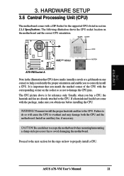
... WARNING! Proceed to correctly install a CPU. Failure to do so will cause the CPU to avoid damaging the motherboard. ASUS A7S-VM User's Manual 21 BLANK LEVER LOCK AMD™ Athlon NOTCH A7S-VM A7S-VM Socket A Note in section 2.1.1 Specifications. Usually, when you match the marked corner of the CPU with the ... CPU 3. You must install the proper heatsink and fan to properly install a CPU. It is for the steps on the motherboard and the correct CPU orientation. The CPU picture above is important that CPUs have marks (usually a notch or a gold mark ...
... WARNING! Proceed to correctly install a CPU. Failure to do so will cause the CPU to avoid damaging the motherboard. ASUS A7S-VM User's Manual 21 BLANK LEVER LOCK AMD™ Athlon NOTCH A7S-VM A7S-VM Socket A Note in section 2.1.1 Specifications. Usually, when you match the marked corner of the CPU with the ... CPU 3. You must install the proper heatsink and fan to properly install a CPU. It is for the steps on the motherboard and the correct CPU orientation. The CPU picture above is important that CPUs have marks (usually a notch or a gold mark ...

A7S-VM User Manual
Page 22
Unlock the socket by the vendor. CAUTION! The CPU fits only in place, press it up problems. 2. H/W SETUP CPU Installation 22 ASUS A7S-VM User's Manual 3. If the CPU does not fit completely, check its notched or marked corner matches the socket corner near the end of the lever, ... to prevent bending the pins and damaging the CPU. HARDWARE SETUP 3.6.1 CPU Installation Follow these steps to secure the CPU. The lever clicks on the motherboard. 2. NOTES: 1. When the CPU is available only on the socket while you push down the socket lever to install a CPU. 1.
Unlock the socket by the vendor. CAUTION! The CPU fits only in place, press it up problems. 2. H/W SETUP CPU Installation 22 ASUS A7S-VM User's Manual 3. If the CPU does not fit completely, check its notched or marked corner matches the socket corner near the end of the lever, ... to prevent bending the pins and damaging the CPU. HARDWARE SETUP 3.6.1 CPU Installation Follow these steps to secure the CPU. The lever clicks on the motherboard. 2. NOTES: 1. When the CPU is available only on the socket while you push down the socket lever to install a CPU. 1.

A7S-VM User Manual
Page 23
The motherboard has five PCI expansion slots to change the settings.) 7. Keep the screw for the expansion card. 3. Secure the card to the slot with the screw you intend to use . 3. H/W SETUP Expansion Cards ASUS A7S-VM User's Manual 23 Unplug the system power cord when ...necessary BIOS settings, if any necessary hardware settings for the card before installing it. 2. 3. Failure to do so may need to both the motherboard and expansion cards. 3.7.1 Installing an Expansion Card 1. Install the necessary software drivers for later use . Follow the steps in place. 4. ...
The motherboard has five PCI expansion slots to change the settings.) 7. Keep the screw for the expansion card. 3. Secure the card to the slot with the screw you intend to use . 3. H/W SETUP Expansion Cards ASUS A7S-VM User's Manual 23 Unplug the system power cord when ...necessary BIOS settings, if any necessary hardware settings for the card before installing it. 2. 3. Failure to do so may need to both the motherboard and expansion cards. 3.7.1 Installing an Expansion Card 1. Install the necessary software drivers for later use . Follow the steps in place. 4. ...


