
X223W LCD Monitor User's Guide
Page 1
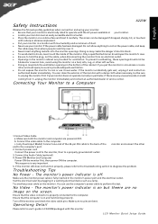
...first. If the monitor accidentally gets wet, unplug it carefully. Make sure both the monitor and computer are bent. Connect the Audio Cable.(optional) 4. Troubleshooting Tips No Power - Turn off . Connecting Your Monitor to the computer's port. 2. The monitor's power indicator is off the monitor and check the... power cable on a solid surface and treat it and contact an authorized dealer immediately. This sequence is very important. English Safety Instructions X223W Observe the folowing safety guidelines when connection and using the monitor on and functioning properly.
...first. If the monitor accidentally gets wet, unplug it carefully. Make sure both the monitor and computer are bent. Connect the Audio Cable.(optional) 4. Troubleshooting Tips No Power - Turn off . Connecting Your Monitor to the computer's port. 2. The monitor's power indicator is off the monitor and check the... power cable on a solid surface and treat it and contact an authorized dealer immediately. This sequence is very important. English Safety Instructions X223W Observe the folowing safety guidelines when connection and using the monitor on and functioning properly.
X223W LCD Monitor User's Guide
Page 18
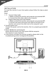
... diagnose the problem. b. Make sure both the monitor and computer are powered-OFF. If the monitor still does not function properly, please refer to the troubleshooting section to the computer's port. 2. This sequence is very important. 4. Power-ON Monitor and Computer Power-ON the monitor first, then power-ON the computer...
... diagnose the problem. b. Make sure both the monitor and computer are powered-OFF. If the monitor still does not function properly, please refer to the troubleshooting section to the computer's port. 2. This sequence is very important. 4. Power-ON Monitor and Computer Power-ON the monitor first, then power-ON the computer...
X223W LCD Monitor User's Guide
Page 25
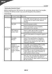
...ON. Abnormal Picture shift, or too small or too large in compliance which may be causing the input signal frequency mismatch. EN-19 X223W TROUBLESHOOTING Before sending your LCD monitor for a few seconds after adjusting the size of the image before changing or disconnecting the signal cable or...power of missing full-screen size image, please select other resolution or other vertical refresh timing. · Wait for servicing, please check the troubleshooting list below to see if you can self-diagnose the problem. (VGA Mode) Problems Current Status Remedy LED ON · Using OSD, ...
...ON. Abnormal Picture shift, or too small or too large in compliance which may be causing the input signal frequency mismatch. EN-19 X223W TROUBLESHOOTING Before sending your LCD monitor for a few seconds after adjusting the size of the image before changing or disconnecting the signal cable or...power of missing full-screen size image, please select other resolution or other vertical refresh timing. · Wait for servicing, please check the troubleshooting list below to see if you can self-diagnose the problem. (VGA Mode) Problems Current Status Remedy LED ON · Using OSD, ...
X223W LCD Service Guide
Page 21
.... Troubleshooting 5.1 No.display of screen (Screen is black, color of LED is connected normally. it is indicated with "Out Of Range" at the Yes time of computer, or change IC movement" section. NG OK Input the sync signal of the frequency that it is indicated with "No Signal Input". 20 ACER X223W Go...
.... Troubleshooting 5.1 No.display of screen (Screen is black, color of LED is connected normally. it is indicated with "Out Of Range" at the Yes time of computer, or change IC movement" section. NG OK Input the sync signal of the frequency that it is indicated with "No Signal Input". 20 ACER X223W Go...
X223W LCD Service Guide
Page 22
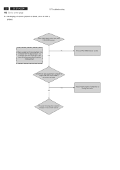
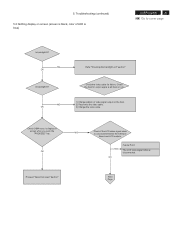
5. Proceed "Abnormal sreen" dection" Next Page Check the host for failure. Troubleshooting (continued) 5.2 Nothing display on screen (screen is display on the host. 2) Reconnect the video cable. 3) Change the video cable. OK NG Check if the LCD ... OK Refer "Checking the backlight unit" section" Check the video cable for output signal is all black or not. 1) Change pattern of LED is blue) ACER X223W 21 Go to cover page Is backlight lit? NG OK Is backlight lit? Check OSM menu is black, color of video signal output on screen...
5. Proceed "Abnormal sreen" dection" Next Page Check the host for failure. Troubleshooting (continued) 5.2 Nothing display on screen (screen is display on the host. 2) Reconnect the video cable. 3) Change the video cable. OK NG Check if the LCD ... OK Refer "Checking the backlight unit" section" Check the video cable for output signal is all black or not. 1) Change pattern of LED is blue) ACER X223W 21 Go to cover page Is backlight lit? NG OK Is backlight lit? Check OSM menu is black, color of video signal output on screen...
X223W LCD Service Guide
Page 23
..., I301 pin1 is failure.. 2) Q301 is failure. Check if the voltage on I305 pin 90 that outputted by I305 pin85 is High level. 22 ACER X223W Go to 1.6V. Troubleshooting (continued) 5.2 Nothing display on the P306 pin 4 (normal is high level, when push buttom, generated 1.6V) Failure Point I301 is failure. OK Check...
..., I301 pin1 is failure.. 2) Q301 is failure. Check if the voltage on I305 pin 90 that outputted by I305 pin85 is High level. 22 ACER X223W Go to 1.6V. Troubleshooting (continued) 5.2 Nothing display on the P306 pin 4 (normal is high level, when push buttom, generated 1.6V) Failure Point I301 is failure. OK Check...

X223W LCD Service Guide
Page 24
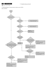
... of the DC input P301 pin2 at TTL high level. Check the BKLT_EN signal of the input P301 pin3 from I305 pin86 is a PWM signal. Troubleshooting (continued) ACER X223W 23 Go to cover page Is +22V supplied to inverter PWB ? (by the power board) NG OK Failure Point Power board of LCD module...
... of the DC input P301 pin2 at TTL high level. Check the BKLT_EN signal of the input P301 pin3 from I305 pin86 is a PWM signal. Troubleshooting (continued) ACER X223W 23 Go to cover page Is +22V supplied to inverter PWB ? (by the power board) NG OK Failure Point Power board of LCD module...
X223W LCD Service Guide
Page 25
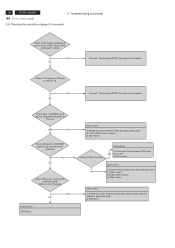
... cover page 5.4 Abnormal screen for VGA 5. Failure Point In the case of video connector. Troubleshooting (continued) Check the R, G, B video signal from host computer, check computer. 2) Video signal cable disconnection. Process "Checking the resolution change IC movement" section. 24 ACER X223W Go to 0.7Vp-p. NG OK Check the R, G, B input video signals on P302 of...
... cover page 5.4 Abnormal screen for VGA 5. Failure Point In the case of video connector. Troubleshooting (continued) Check the R, G, B video signal from host computer, check computer. 2) Video signal cable disconnection. Process "Checking the resolution change IC movement" section. 24 ACER X223W Go to 0.7Vp-p. NG OK Check the R, G, B input video signals on P302 of...
X223W LCD Service Guide
Page 26
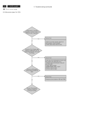
... I305 pin89. 3)C386,C388 ,C389,C390 are short. Failure Point I305 is failure. R369 and I305 pin90. 2) Printed wire broke among P306 pin4, pin5; Troubleshooting (continued) ACER X223W 25 Go to cover page Check the input TTL level whether was changed when pressed function keys on the P306 pin 4, 5 (normal is high level...
... I305 pin89. 3)C386,C388 ,C389,C390 are short. Failure Point I305 is failure. R369 and I305 pin90. 2) Printed wire broke among P306 pin4, pin5; Troubleshooting (continued) ACER X223W 25 Go to cover page Check the input TTL level whether was changed when pressed function keys on the P306 pin 4, 5 (normal is high level...
X223W LCD Service Guide
Page 27
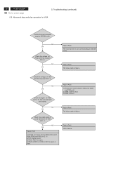
... Check the signal on I303 pin5, 6. NG OK Failure Point The host machine is failure. Failure Point I303 is not communicatiog in DDC2B mode. 26 ACER X223W Go to cover page 5.6 Abnormal plug and play operation for VGA 5. Troubleshooting (continued) Confirm the host computer supplies DDC2B mode.
... Check the signal on I303 pin5, 6. NG OK Failure Point The host machine is failure. Failure Point I303 is not communicatiog in DDC2B mode. 26 ACER X223W Go to cover page 5.6 Abnormal plug and play operation for VGA 5. Troubleshooting (continued) Confirm the host computer supplies DDC2B mode.
X223W LCD Service Guide
Page 28
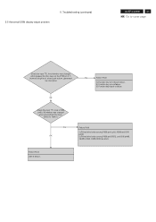
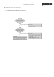
NG OK Failure Point Process "Checking the resolution change IC movement" section. Failure Point 1) Printed wire broke between P302 pin13 and I305 pin27. 2) FB309, R321 are short. 3) D307 or R324 or C327 is failure. Failure Point Video cable is short. 5. NG OK Check the horizontal sync signal on P302 pin13 TTL level. Troubleshooting (continued) 5.7 Checking the interface circuit of sync signal 5.7.1 Checking the control circuit of horizontal sync pulse ACER X223W 27 Go to cover page Check the horizontal sync signal on I305 pin27 TTL level.
NG OK Failure Point Process "Checking the resolution change IC movement" section. Failure Point 1) Printed wire broke between P302 pin13 and I305 pin27. 2) FB309, R321 are short. 3) D307 or R324 or C327 is failure. Failure Point Video cable is short. 5. NG OK Check the horizontal sync signal on P302 pin13 TTL level. Troubleshooting (continued) 5.7 Checking the interface circuit of sync signal 5.7.1 Checking the control circuit of horizontal sync pulse ACER X223W 27 Go to cover page Check the horizontal sync signal on I305 pin27 TTL level.
X223W LCD Service Guide
Page 29
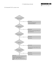
28 ACER X223W Go to I305 pin96 and pin97 at normal operation. Check +1.8V supply on I305 pin8, pin14, pin16, pin24 , pin32, pin49, pin56, pin75, pin98 NG OK ... or open. 3) X301 failure. OK 2) C381 is short. 3) R358, D328 is failure 4) I305 is failure Failure Point 1) Printed wire broke between I305 pin84 and C378. Troubleshooting (continued) 5.8 Checking the resolution change IC movement Check +3.3V supply on I305 pin 51, 66, 82, 34. NG OK Proceed " Checking the DC/DC converter...
28 ACER X223W Go to I305 pin96 and pin97 at normal operation. Check +1.8V supply on I305 pin8, pin14, pin16, pin24 , pin32, pin49, pin56, pin75, pin98 NG OK ... or open. 3) X301 failure. OK 2) C381 is short. 3) R358, D328 is failure 4) I305 is failure Failure Point 1) Printed wire broke between I305 pin84 and C378. Troubleshooting (continued) 5.8 Checking the resolution change IC movement Check +3.3V supply on I305 pin 51, 66, 82, 34. NG OK Proceed " Checking the DC/DC converter...
X223W LCD Service Guide
Page 30
Troubleshooting (continued) ACER X223W 29 Go to Q305 pin1. NG OK Failure Point 1) Power wire disconnection. 2) Power board is failure. Failure Point D326 is failure. Failure Point I302 is ...
Troubleshooting (continued) ACER X223W 29 Go to Q305 pin1. NG OK Failure Point 1) Power wire disconnection. 2) Power board is failure. Failure Point D326 is failure. Failure Point I302 is ...


