
X223W LCD Monitor User's Guide
Page 5
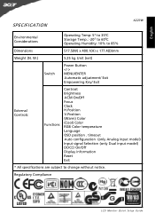
timeout Auto configuration (only Analog input model) Input signal Selection (only Dual input model) DDCCI On/Off Display information Reset Exit * All specifications are subject to 85% Dimensions 517.5(W) x 400.1(H) x 177.4(D)mm Weight (N. English SPECIFICATION X223W Environmental Considerations Operating Temp: 50 to 350C Storage Temp.: -200 to 600C Operating Humidity: 10% to change...
timeout Auto configuration (only Analog input model) Input signal Selection (only Dual input model) DDCCI On/Off Display information Reset Exit * All specifications are subject to 85% Dimensions 517.5(W) x 400.1(H) x 177.4(D)mm Weight (N. English SPECIFICATION X223W Environmental Considerations Operating Temp: 50 to 350C Storage Temp.: -200 to 600C Operating Humidity: 10% to change...
X223W LCD Monitor User's Guide
Page 14
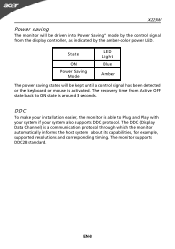
... Data Channel) is around 3 seconds. EN-8 State ON Power Saving Mode LED Light Blue Amber The power saving states will be kept until a control signal has been detected or the keyboard or mouse is activated. The monitor supports DDC2B standard. The recovery time from the display controller, as indicated by... informs the host system about its capabilities, for example, supported resolutions and corresponding timing. DDC To make your system also supports DDC protocol. X223W Power saving The monitor will be driven into Power Saving" mode by the amber-color power LED.
... Data Channel) is around 3 seconds. EN-8 State ON Power Saving Mode LED Light Blue Amber The power saving states will be kept until a control signal has been detected or the keyboard or mouse is activated. The monitor supports DDC2B standard. The recovery time from the display controller, as indicated by... informs the host system about its capabilities, for example, supported resolutions and corresponding timing. DDC To make your system also supports DDC protocol. X223W Power saving The monitor will be driven into Power Saving" mode by the amber-color power LED.
X223W LCD Monitor User's Guide
Page 15
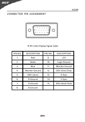
CONNECTOR PIN ASSIGNMENT X223W 15-Pin Color Display Signal Cable PIN NO. 1. 2. 3. 4. 5. 6. 7. 8. DESCRIPTION Red Green Blue Monitor Ground DDC-return R-Ground G-Ground B-Ground PIN NO. 9. 10. 11. 12. 13. 14. 15. DESCRIPTION +5V Logic Ground Monitor Ground DDC-Serial Data H-Sync V-Sync DDC-Serial Clock EN-9
CONNECTOR PIN ASSIGNMENT X223W 15-Pin Color Display Signal Cable PIN NO. 1. 2. 3. 4. 5. 6. 7. 8. DESCRIPTION Red Green Blue Monitor Ground DDC-return R-Ground G-Ground B-Ground PIN NO. 9. 10. 11. 12. 13. 14. 15. DESCRIPTION +5V Logic Ground Monitor Ground DDC-Serial Data H-Sync V-Sync DDC-Serial Clock EN-9
X223W LCD Monitor User's Guide
Page 16
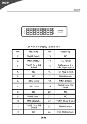
TMDS Data2- 13. NC 17. TMDS Data0+ 7. NC 20. NC 24. NC 2. Hot Plug Detect 5. TMDS Data1- 21. TMDS Data0- 6. TMDS Clock+ 12. TMDS Data 2/4 Shield 15. NC 9. NC 10. EN-10 GND(return for +5V hsync.vsync) 4. TMDS Data2+ 14. +5V Power 3. DDC Data 19. TMDS Data 1/3 Shield 23. DDC Clock 18. X223W 24-Pin Color Display Signal Cable PIN Meaning PIN Meaning 1. TMDS Data1+ 22. DDC TMDS Clock- NC 16. TMDS Data 0/5 Shield 8. TMDS Clock Shield 11.
TMDS Data2- 13. NC 17. TMDS Data0+ 7. NC 20. NC 24. NC 2. Hot Plug Detect 5. TMDS Data1- 21. TMDS Data0- 6. TMDS Clock+ 12. TMDS Data 2/4 Shield 15. NC 9. NC 10. EN-10 GND(return for +5V hsync.vsync) 4. TMDS Data2+ 14. +5V Power 3. DDC Data 19. TMDS Data 1/3 Shield 23. DDC Clock 18. X223W 24-Pin Color Display Signal Cable PIN Meaning PIN Meaning 1. TMDS Data1+ 22. DDC TMDS Clock- NC 16. TMDS Data 0/5 Shield 8. TMDS Clock Shield 11.
X223W LCD Monitor User's Guide
Page 17
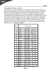
... is capable of the mode is matched, the user can store their preferred modes in the user modes. X223W Standard Timing Table To reduce the need for adjustment for vertical frequency or the sync signal polarities are most commonly used as given in the table below. For optimum adjustment, the user is...
... is capable of the mode is matched, the user can store their preferred modes in the user modes. X223W Standard Timing Table To reduce the need for adjustment for vertical frequency or the sync signal polarities are most commonly used as given in the table below. For optimum adjustment, the user is...
X223W LCD Monitor User's Guide
Page 23
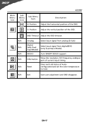
Main Menu Icon X223W Sub Menu Icon Sub Menu Item H. EN-17 N/A Reset Clear each old status of the OSD. Position Description Adjust the horizontal position of Autoconfigurationand set the color temperature to Cool. V. N/A Analog Select input signal from analog (D-Sub) N/A Digital (only DualInputModel) Select input signal from digital(DVI) (only Dual-Input Model...
Main Menu Icon X223W Sub Menu Icon Sub Menu Item H. EN-17 N/A Reset Clear each old status of the OSD. Position Description Adjust the horizontal position of Autoconfigurationand set the color temperature to Cool. V. N/A Analog Select input signal from analog (D-Sub) N/A Digital (only DualInputModel) Select input signal from digital(DVI) (only Dual-Input Model...
X223W LCD Monitor User's Guide
Page 25
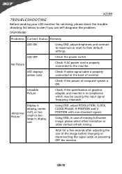
...settings. Abnormal Picture shift, or too small or too large in compliance which may be causing the input signal frequency mismatch. LED displays amber color · Check if video signal cable is properly connected at the back of monitor. · Check if the power of the image ... · Check if the specification of graphics adapter and monitor is in display · POSITION with non-standard signals. LED OFF · Check the power switch. EN-19 X223W TROUBLESHOOTING Before sending your LCD monitor for a few seconds after adjusting the size of computer system is ON. No...
...settings. Abnormal Picture shift, or too small or too large in compliance which may be causing the input signal frequency mismatch. LED displays amber color · Check if video signal cable is properly connected at the back of monitor. · Check if the power of the image ... · Check if the specification of graphics adapter and monitor is in display · POSITION with non-standard signals. LED OFF · Check the power switch. EN-19 X223W TROUBLESHOOTING Before sending your LCD monitor for a few seconds after adjusting the size of computer system is ON. No...

X223W LCD Monitor User's Guide
Page 26
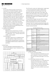
(DVI Mode) X223W Problems No Picture Current Status Remedy LED ON · Using OSD, adjust brightness and contrast to maximum or reset to the monitor. LED OFF · Check the power switch. · Check if AC power cord is ON. EN-20 LED displays amber color · Check if video signal cable is properly connected at the back of monitor. · Check if the power of computer system is properly connected to their default settings.
(DVI Mode) X223W Problems No Picture Current Status Remedy LED ON · Using OSD, adjust brightness and contrast to maximum or reset to the monitor. LED OFF · Check the power switch. · Check if AC power cord is ON. EN-20 LED displays amber color · Check if video signal cable is properly connected at the back of monitor. · Check if the power of computer system is properly connected to their default settings.
X223W LCD Service Guide
Page 3
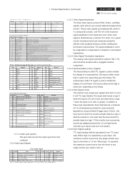
...OFF control over , shielded,triple row, 15 position, D-subminiature connector. The power cord shall be 1.8 +/-0.005 meters long. 2 ACER X223W Go to AC Inverter. The CPU connection shall have an IEC/CEE-22 type male power receptacle for an 20/22W inch diagonal ,...Clock ,Phase ,Analog/Digital,RESET, Color , Language select , Audio (option), etc. 19 User 9 Plug and Play VESA DDC2Bi Power Saving VESA DPMS Input Signal Counter Tolerance ≦ H ± 1kHz, ≦ V ± 1 Hz 1.3.1 Interface Connectors 1.3.1.1 Power Connector and Cables The AC input shall have ...
...OFF control over , shielded,triple row, 15 position, D-subminiature connector. The power cord shall be 1.8 +/-0.005 meters long. 2 ACER X223W Go to AC Inverter. The CPU connection shall have an IEC/CEE-22 type male power receptacle for an 20/22W inch diagonal ,...Clock ,Phase ,Analog/Digital,RESET, Color , Language select , Audio (option), etc. 19 User 9 Plug and Play VESA DDC2Bi Power Saving VESA DPMS Input Signal Counter Tolerance ≦ H ± 1kHz, ≦ V ± 1 Hz 1.3.1 Interface Connectors 1.3.1.1 Power Connector and Cables The AC input shall have ...
X223W LCD Service Guide
Page 4
... GND 6 SCL 16 HP 7 SCA 17 RX0- 8 Analog V-Sync (NC) 18 RX0+ 9 RX1- 19 GND 10 RX1+ 20 NC Pin Signal 21 NC 22 GND 23 RXC+ 24 RXC- 1. Product Specification (continued) ACER X223W 3 Go to cover page C o n n e c to r P in A ssig n m e n t D SU B P in 1 S ig n a l R e d -V id e o P in 6 2 G re e n -V id e o 7 3 B lu e -V id e o 8 4 NC 9 5 D D C -G N D 10 S ig...
... GND 6 SCL 16 HP 7 SCA 17 RX0- 8 Analog V-Sync (NC) 18 RX0+ 9 RX1- 19 GND 10 RX1+ 20 NC Pin Signal 21 NC 22 GND 23 RXC+ 24 RXC- 1. Product Specification (continued) ACER X223W 3 Go to cover page C o n n e c to r P in A ssig n m e n t D SU B P in 1 S ig n a l R e d -V id e o P in 6 2 G re e n -V id e o 7 3 B lu e -V id e o 8 4 NC 9 5 D D C -G N D 10 S ig...
X223W LCD Service Guide
Page 5
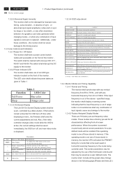
4 ACER X223W Go to the monitor 1.3.3.2 Power Indicator LED The monitor shall make use...input is not input (AC line power consumption 2W or less). COLOR BALANCE Select three kinds of R , G and B signal is active, the current settings shall be adjusted. The LED color shall indicate the power states as a user defined mode. ...front-of the monitor . Key MENU > < Auto Description When no circumstances shall any combination of R , G and B signal auto adjust. Speaker Volume/Plus 1. If the input frequency is adjusted. The screen parameters may be adjusted by the use of...
4 ACER X223W Go to the monitor 1.3.3.2 Power Indicator LED The monitor shall make use...input is not input (AC line power consumption 2W or less). COLOR BALANCE Select three kinds of R , G and B signal is active, the current settings shall be adjusted. The LED color shall indicate the power states as a user defined mode. ...front-of the monitor . Key MENU > < Auto Description When no circumstances shall any combination of R , G and B signal auto adjust. Speaker Volume/Plus 1. If the input frequency is adjusted. The screen parameters may be adjusted by the use of...
X223W LCD Service Guide
Page 6
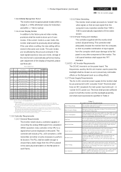
...''. (4) User mode : The code should memorize 9 timing mode exclusive of converting the analog RGB signal from 90 to 132 and 195 to user modes. Product Specification (continued) ACER X223W 5 Go to cover page 1.3.4.3 Mode Recognition Pull-in the CPU to DC Converter Requirements The operating... Voltage Range Input Frequency Range Power Consumption Line Fuse Initial Cold Start Inrush Current Hot Start Cycle Under Voltage Line Transient Table 2 AC to a signal which can display but doesn't guarantee. (2) fV < 55, or fV > 86 : warning invalid mode. (3) Factory model : After we...
...''. (4) User mode : The code should memorize 9 timing mode exclusive of converting the analog RGB signal from 90 to 132 and 195 to user modes. Product Specification (continued) ACER X223W 5 Go to cover page 1.3.4.3 Mode Recognition Pull-in the CPU to DC Converter Requirements The operating... Voltage Range Input Frequency Range Power Consumption Line Fuse Initial Cold Start Inrush Current Hot Start Cycle Under Voltage Line Transient Table 2 AC to a signal which can display but doesn't guarantee. (2) fV < 55, or fV > 86 : warning invalid mode. (3) Factory model : After we...
X223W LCD Service Guide
Page 21
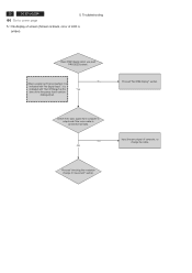
...ACER X223W Go to cover page 5. it is amber) Does OSM display when you push PROCEED buttom. Proceed "No OSM display" section. Proceed "checking the resolution change the cable. NG OK Input the sync signal of the frequency that it is connected normally. Check if the sync signal ...from computer is output and if the video cable is indicated with "Out Of Range" at the Yes time of computer, or change IC movement" section. No When a signal isn't being inputted, it can't be distinguished. ...
...ACER X223W Go to cover page 5. it is amber) Does OSM display when you push PROCEED buttom. Proceed "No OSM display" section. Proceed "checking the resolution change the cable. NG OK Input the sync signal of the frequency that it is connected normally. Check if the sync signal ...from computer is output and if the video cable is indicated with "Out Of Range" at the Yes time of computer, or change IC movement" section. No When a signal isn't being inputted, it can't be distinguished. ...
X223W LCD Service Guide
Page 22
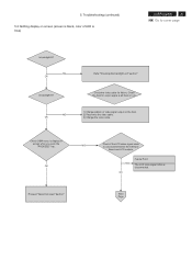
...Change the video cable. Proceed "Abnormal sreen" dection" Next Page NG OK Is backlight lit? NG OK Failure Point The LCD video signal cable is connected between the Interface Board and LCD module. NG OK Refer "Checking the backlight unit" section" Check the video cable for output... signal is all black or not. 1) Change pattern of LED is black, color of video signal output on screen when you push the "PROCEED" key. Troubleshooting (continued) 5.2 Nothing display on screen (screen is blue) ACER X223W 21 Go to cover page Is backlight ...
...Change the video cable. Proceed "Abnormal sreen" dection" Next Page NG OK Is backlight lit? NG OK Failure Point The LCD video signal cable is connected between the Interface Board and LCD module. NG OK Refer "Checking the backlight unit" section" Check the video cable for output... signal is all black or not. 1) Change pattern of LED is black, color of video signal output on screen when you push the "PROCEED" key. Troubleshooting (continued) 5.2 Nothing display on screen (screen is blue) ACER X223W 21 Go to cover page Is backlight ...
X223W LCD Service Guide
Page 23
... Point NG Failure Point 1) Printer wire between R307 and I305 pin85 is failure 2) I305 is failure. 1) Printed wire between P304 and I305 LVDS signals. 2) I305 is 1.8V NG Proceed "Checking the DC/DC converter circuit" section. Failure Point Printed wire broke between P304 and LCD module. 2)...) continued Continue Check the 5V power supply for P304 pin 1, 2, 3 NG Check the I302 pin2 NG if voltage is High level. 22 ACER X223W Go to 1.6V. Troubleshooting (continued) 5.2 Nothing display on I305 pin 90 that outputted by I305 pin85 is 3.3V Proceed "Checking the DC/...
... Point NG Failure Point 1) Printer wire between R307 and I305 pin85 is failure 2) I305 is failure. 1) Printed wire between P304 and I305 LVDS signals. 2) I305 is 1.8V NG Proceed "Checking the DC/DC converter circuit" section. Failure Point Printed wire broke between P304 and LCD module. 2)...) continued Continue Check the 5V power supply for P304 pin 1, 2, 3 NG Check the I302 pin2 NG if voltage is High level. 22 ACER X223W Go to 1.6V. Troubleshooting (continued) 5.2 Nothing display on I305 pin 90 that outputted by I305 pin85 is 3.3V Proceed "Checking the DC/...

X223W LCD Service Guide
Page 24
...NG OK Failure Point 1) printed wire broke between P301 pin3, R301 and I305 pin86. 2) I305 is failure. Check the BKLT_EN signal of Inverter part failure. Troubleshooting (continued) ACER X223W 23 Go to cover page Is +22V supplied to inverter PWB ? (by the power board) NG OK Failure Point Power ...board of the DC input P301 pin2 at TTL high level. Check the BKLT_ADJ signal of LCD module is failure. 2) ...
...NG OK Failure Point 1) printed wire broke between P301 pin3, R301 and I305 pin86. 2) I305 is failure. Check the BKLT_EN signal of Inverter part failure. Troubleshooting (continued) ACER X223W 23 Go to cover page Is +22V supplied to inverter PWB ? (by the power board) NG OK Failure Point Power ...board of the DC input P301 pin2 at TTL high level. Check the BKLT_ADJ signal of LCD module is failure. 2) ...
X223W LCD Service Guide
Page 25
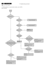
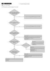
...check computer. 2) Video signal cable disconnection. Failure Point Printed wire broke between P302 pin1 and I306 pin23. 2) Video cable is failure. 3) FB303,FB304, R309 is open. 4) R311 is short or open. 5) C315 is 0.0 to cover page 5.4 Abnormal screen for VGA 5. 24 ACER X223W Go to 0.7Vp-p.... Troubleshooting (continued) Check the R, G, B video signal from computer input on I305 pin18, 20, 23 respectively that their level is short or open.
...check computer. 2) Video signal cable disconnection. Failure Point Printed wire broke between P302 pin1 and I306 pin23. 2) Video cable is failure. 3) FB303,FB304, R309 is open. 4) R311 is short or open. 5) C315 is 0.0 to cover page 5.4 Abnormal screen for VGA 5. 24 ACER X223W Go to 0.7Vp-p.... Troubleshooting (continued) Check the R, G, B video signal from computer input on I305 pin18, 20, 23 respectively that their level is short or open.
X223W LCD Service Guide
Page 27
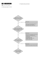
Failure Point The Video cable is open or short. NG OK Check the signal on I303 pin8 that is serial data / clock signal. NG OK Failure Point 1) Printed wire broke among I305 pin30, pin31, R328,R330 and P302 pin12, 15 . 2) I303 maybe failure. 3) R326, R327 are open. 4) ... Confirm the host computer supplies DDC2B mode. Failure Point The Video cable is failure. NG OK Check the voltage on I303 pin5, 6. 26 ACER X223W Go to cover page 5.6 Abnormal plug and play operation for VGA 5. NG OK Check the output signal of serial data/clock on P302 pin9 that is power DC 5 V.
Failure Point The Video cable is open or short. NG OK Check the signal on I303 pin8 that is serial data / clock signal. NG OK Failure Point 1) Printed wire broke among I305 pin30, pin31, R328,R330 and P302 pin12, 15 . 2) I303 maybe failure. 3) R326, R327 are open. 4) ... Confirm the host computer supplies DDC2B mode. Failure Point The Video cable is failure. NG OK Check the voltage on I303 pin5, 6. 26 ACER X223W Go to cover page 5.6 Abnormal plug and play operation for VGA 5. NG OK Check the output signal of serial data/clock on P302 pin9 that is power DC 5 V.
X223W LCD Service Guide
Page 28
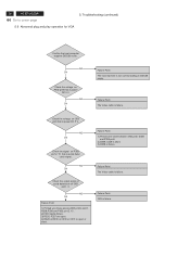
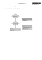
Failure Point 1) Printed wire broke between P302 pin13 and I305 pin27. 2) FB309, R321 are short. 3) D307 or R324 or C327 is failure. 5. NG OK Check the horizontal sync signal on P302 pin13 TTL level. NG OK Failure Point Process "Checking the resolution change IC movement" section. Troubleshooting (continued) 5.7 Checking the interface circuit of sync signal 5.7.1 Checking the control circuit of horizontal sync pulse ACER X223W 27 Go to cover page Check the horizontal sync signal on I305 pin27 TTL level. Failure Point Video cable is short.
Failure Point 1) Printed wire broke between P302 pin13 and I305 pin27. 2) FB309, R321 are short. 3) D307 or R324 or C327 is failure. 5. NG OK Check the horizontal sync signal on P302 pin13 TTL level. NG OK Failure Point Process "Checking the resolution change IC movement" section. Troubleshooting (continued) 5.7 Checking the interface circuit of sync signal 5.7.1 Checking the control circuit of horizontal sync pulse ACER X223W 27 Go to cover page Check the horizontal sync signal on I305 pin27 TTL level. Failure Point Video cable is short.
X223W LCD Service Guide
Page 29
... level at TTL level. Check X301 14.318MHz clock input to cover page 5. NG OK Check I305 pin37, pin38, pin39, pin40 SPI signal (Same as the IIC signal). NG OK Failure Point 1) Printed wire broke between I305 pin84 NG and C378 2) C78 is short or open. 3) X301 failure. Failure... Point 1) Printer wire broke between I305 pin37, pin38, pin39, pin40 and I306 pin1, pin2, pin5, pin6. 2) I306 failure. Failure Point I306 failure. 28 ACER X223W Go ...
... level at TTL level. Check X301 14.318MHz clock input to cover page 5. NG OK Check I305 pin37, pin38, pin39, pin40 SPI signal (Same as the IIC signal). NG OK Failure Point 1) Printed wire broke between I305 pin84 NG and C378 2) C78 is short or open. 3) X301 failure. Failure... Point 1) Printer wire broke between I305 pin37, pin38, pin39, pin40 and I306 pin1, pin2, pin5, pin6. 2) I306 failure. Failure Point I306 failure. 28 ACER X223W Go ...


