User Manual
Page 9
... includes Hardware Monitor, Fan Control, Overclocking, OC DNA and IES. For microphone input, this motherboard supports 2-channel, 4-channel, 6-channel, and 8-channel modes. For audio output, this motherboard supports both stereo and mono modes. ASRock Extreme Tuning Utility (AXTU) is already PCIE 3.0 hardware ready. In OC DNA, you implement Quad Channel Memory Technology, make sure to enable PCIE 3.0. We are allowed to adjust. Before you can work properly. 4. For Windows® OS with 64-bit CPU, there is...
... includes Hardware Monitor, Fan Control, Overclocking, OC DNA and IES. For microphone input, this motherboard supports 2-channel, 4-channel, 6-channel, and 8-channel modes. For audio output, this motherboard supports both stereo and mono modes. ASRock Extreme Tuning Utility (AXTU) is already PCIE 3.0 hardware ready. In OC DNA, you implement Quad Channel Memory Technology, make sure to enable PCIE 3.0. We are allowed to adjust. Before you can work properly. 4. For Windows® OS with 64-bit CPU, there is...
User Manual
Page 10
... the key during the POST or the key to RAM (S3), hibernation mode (S4) or power off (S5). Real-Time Analysis of ASRock Extreme Tuning Utility (AXTU). ASRock website: http://www.asrock.com/Feature/SmartView/index.asp 11. ASRock XFast USB can watch Youtube HD videos and download simultaneously. Traf c Shaping: You can boost USB storage device performance. LAN Application Prioritization: You can lower the latency in Flash ROM. With...
... the key during the POST or the key to RAM (S3), hibernation mode (S4) or power off (S5). Real-Time Analysis of ASRock Extreme Tuning Utility (AXTU). ASRock website: http://www.asrock.com/Feature/SmartView/index.asp 11. ASRock XFast USB can watch Youtube HD videos and download simultaneously. Traf c Shaping: You can boost USB storage device performance. LAN Application Prioritization: You can lower the latency in Flash ROM. With...
User Manual
Page 12
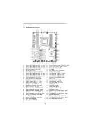
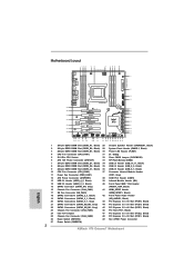
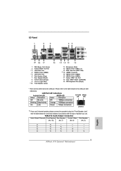
... Slot (DDR3_A1, Black) 28 Chassis Speaker Header (SPEAKER1, Black) 2 240-pin DDR3 DIMM Slot (DDR3_B2, Black) 29 System Panel Header (PANEL1, Black) 3 240-pin DDR3 DIMM Slot (DDR3_B1, Black) 30 Power LED Header (PLED1) 4 CPU Fan Connector (CPU_FAN1) 31 Dr. Debug 5 2011-Pin CPU Socket 32 Clear CMOS Jumper (CLRCMOS1) 6 ATX 12V Power Connector (ATX12V1) 33 SPI Flash Memory (64Mb) 7 240-pin DDR3 DIMM Slot (DDR3_D1, Black) 34 USB 2.0 Header (USB_10_11, Black) 8 240-pin DDR3 DIMM Slot (DDR3_D2, Black) 35 USB 2.0 Header (USB_8_9, Black) 9 240-pin...
... Slot (DDR3_A1, Black) 28 Chassis Speaker Header (SPEAKER1, Black) 2 240-pin DDR3 DIMM Slot (DDR3_B2, Black) 29 System Panel Header (PANEL1, Black) 3 240-pin DDR3 DIMM Slot (DDR3_B1, Black) 30 Power LED Header (PLED1) 4 CPU Fan Connector (CPU_FAN1) 31 Dr. Debug 5 2011-Pin CPU Socket 32 Clear CMOS Jumper (CLRCMOS1) 6 ATX 12V Power Connector (ATX12V1) 33 SPI Flash Memory (64Mb) 7 240-pin DDR3 DIMM Slot (DDR3_D1, Black) 34 USB 2.0 Header (USB_10_11, Black) 8 240-pin DDR3 DIMM Slot (DDR3_D2, Black) 35 USB 2.0 Header (USB_8_9, Black) 9 240-pin...
User Manual
Page 32
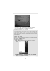
... VGA driver installed in your Windows® taskbar. Step 3. Click "View", select "CrossFireXTM", and then check the item "Enable CrossFireXTM". Step 5. AMD recommends Windows® XP Service Pack 2 or higher to your computer and boot into OS. Power on your system, there is an optional download. Install the required drivers to be installed (If you will nd "ATI Catalyst Control Center" on your system. Install the VGA card drivers to installation...
... VGA driver installed in your Windows® taskbar. Step 3. Click "View", select "CrossFireXTM", and then check the item "Enable CrossFireXTM". Step 5. AMD recommends Windows® XP Service Pack 2 or higher to your computer and boot into OS. Power on your system, there is an optional download. Install the required drivers to be installed (If you will nd "ATI Catalyst Control Center" on your system. Install the VGA card drivers to installation...
User Manual
Page 48
... Enable Setup Verifying Password Start of Setup Reserved for ASL (see ASL Status Codes section below) Setup Input Wait Reserved for ASL (see ASL Status Codes section below) Ready To Boot event Legacy Boot event Exit Boot Services event Runtime Set Virtual Address MAP Begin Runtime Set Virtual Address MAP End Legacy Option ROM Initialization System Reset USB hot plug PCI bus hot plug Clean-up of NVRAM Con guration Reset (reset of NVRAM settings) Reserved for future AMI codes...
... Enable Setup Verifying Password Start of Setup Reserved for ASL (see ASL Status Codes section below) Setup Input Wait Reserved for ASL (see ASL Status Codes section below) Ready To Boot event Legacy Boot event Exit Boot Services event Runtime Set Virtual Address MAP Begin Runtime Set Virtual Address MAP End Legacy Option ROM Initialization System Reset USB hot plug PCI bus hot plug Clean-up of NVRAM Con guration Reset (reset of NVRAM settings) Reserved for future AMI codes...
User Manual
Page 53
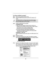
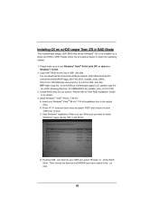
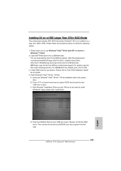
... Rapid Storage" will be auto-detected and listed on the support CD driver page. A. Enter UEFI SETUP UTILITY Advanced screen Storage Con guration. 2.21 Driver Installation Guide To install the drivers to your system, please insert the support CD to your system. Then, the drivers compatible to [RAID] for RAID con guration. Set the option "Marvell SATA3 Operation Mode" to your system can work properly. 2.22 Installing Windows® 7 / 7 64-bit / VistaTM / VistaTM 64-bit With RAID Functions RAID mode is located in...
... Rapid Storage" will be auto-detected and listed on the support CD driver page. A. Enter UEFI SETUP UTILITY Advanced screen Storage Con guration. 2.21 Driver Installation Guide To install the drivers to your system, please insert the support CD to your system. Then, the drivers compatible to [RAID] for RAID con guration. Set the option "Marvell SATA3 Operation Mode" to your system can work properly. 2.22 Installing Windows® 7 / 7 64-bit / VistaTM / VistaTM 64-bit With RAID Functions RAID mode is located in...
User Manual
Page 75
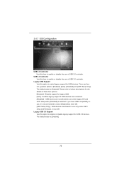
...Auto], [Disabled] and [UEFI Setup Only]. USB devices are allowed to use only under legacy OS and UEFI setup when [Disabled] is [Enabled]. 75 3.4.7 USB Configuration USB 2.0 Controller Use this item to enable or disable the use of USB 3.0 controller. The default value is selected. Enables support for the details of these four options: [Enabled] - If you have USB compatibility issue, it is [Enabled]. Legacy USB 3.0 Support Use this option to select legacy support for USB 3.0 devices. Legacy USB Support Use this item to enter OS. [UEFI Setup Only] - USB 3.0 Controller...
...Auto], [Disabled] and [UEFI Setup Only]. USB devices are allowed to use only under legacy OS and UEFI setup when [Disabled] is [Enabled]. 75 3.4.7 USB Configuration USB 2.0 Controller Use this item to enable or disable the use of USB 3.0 controller. The default value is selected. Enables support for the details of these four options: [Enabled] - If you have USB compatibility issue, it is [Enabled]. Legacy USB 3.0 Support Use this option to select legacy support for USB 3.0 devices. Legacy USB Support Use this item to enter OS. [UEFI Setup Only] - USB 3.0 Controller...
User Manual
Page 81
... support CD, insert the CD into your computer. or you need to contact ASRock or want to know more information. 4.2 Support CD Information The Support CD that came with the motherboard contains necessary drivers and useful utilities that the motherboard supports. Please install the necessary drivers to visit ASRock's website at http://www.asrock.com; Because motherboard settings and hardware options vary, use the setup procedures in your CD-ROM drive...
... support CD, insert the CD into your computer. or you need to contact ASRock or want to know more information. 4.2 Support CD Information The Support CD that came with the motherboard contains necessary drivers and useful utilities that the motherboard supports. Please install the necessary drivers to visit ASRock's website at http://www.asrock.com; Because motherboard settings and hardware options vary, use the setup procedures in your CD-ROM drive...
User Manual
Page 83
... the optical drive. Install Windows® VistaTM 64-bit / 7 64-bit: A. Press to launch boot menu at system POST and choose the item "UEFI:xxx" to install the operating system. 1. Then choose the directory (xx\AMD64\) you want to be installed on a large size HDD (>2TB). When you see "Where do you have copied in RAID Mode This motherboard adopts UEFI BIOS that allows Windows® OS to install Windows?" Please...
... the optical drive. Install Windows® VistaTM 64-bit / 7 64-bit: A. Press to launch boot menu at system POST and choose the item "UEFI:xxx" to install the operating system. 1. Then choose the directory (xx\AMD64\) you want to be installed on a large size HDD (>2TB). When you see "Where do you have copied in RAID Mode This motherboard adopts UEFI BIOS that allows Windows® OS to install Windows?" Please...
User Manual
Page 84
...-bit in the Start Menu. Then Press "Ok". 84 E. Type "systempropertiesprotection" in a large hard disk (ex. b. The steps listed below are Microsoft®'s suggested solution: A. Then Click "Turn System Restore Off" to install OS by following instructions to x this problem. Disk volume > 2TB), it may take more time to install OS. F. Follow Windows® Installation Guide to boot into Windows® or install driver/ utilities. Then press "Enter". Please keep the USB ash disk installed...
...-bit in the Start Menu. Then Press "Ok". 84 E. Type "systempropertiesprotection" in a large hard disk (ex. b. The steps listed below are Microsoft®'s suggested solution: A. Then Click "Turn System Restore Off" to install OS by following instructions to x this problem. Disk volume > 2TB), it may take more time to install OS. F. Follow Windows® Installation Guide to boot into Windows® or install driver/ utilities. Then press "Enter". Please keep the USB ash disk installed...
Quick Installation Guide
Page 2
... Slot (DDR3_A1, Black) 28 Chassis Speaker Header (SPEAKER1, Black) 2 240-pin DDR3 DIMM Slot (DDR3_B2, Black) 29 System Panel Header (PANEL1, Black) 3 240-pin DDR3 DIMM Slot (DDR3_B1, Black) 30 Power LED Header (PLED1) 4 CPU Fan Connector (CPU_FAN1) 31 Dr. Debug 5 2011-Pin CPU Socket 32 Clear CMOS Jumper (CLRCMOS1) 6 ATX 12V Power Connector (ATX12V1) 33 SPI Flash Memory (64Mb) 7 240-pin DDR3 DIMM Slot (DDR3_D1, Black) 34 USB 2.0 Header (USB_10_11, Black) 8 240-pin DDR3 DIMM Slot (DDR3_D2, Black) 35 USB 2.0 Header (USB_8_9, Black) 9 240-pin...
... Slot (DDR3_A1, Black) 28 Chassis Speaker Header (SPEAKER1, Black) 2 240-pin DDR3 DIMM Slot (DDR3_B2, Black) 29 System Panel Header (PANEL1, Black) 3 240-pin DDR3 DIMM Slot (DDR3_B1, Black) 30 Power LED Header (PLED1) 4 CPU Fan Connector (CPU_FAN1) 31 Dr. Debug 5 2011-Pin CPU Socket 32 Clear CMOS Jumper (CLRCMOS1) 6 ATX 12V Power Connector (ATX12V1) 33 SPI Flash Memory (64Mb) 7 240-pin DDR3 DIMM Slot (DDR3_D1, Black) 34 USB 2.0 Header (USB_10_11, Black) 8 240-pin DDR3 DIMM Slot (DDR3_D2, Black) 35 USB 2.0 Header (USB_8_9, Black) 9 240-pin...
Quick Installation Guide
Page 3
...) Front Speaker (Lime) 15 14 13 12 11 12 13 *** 14 15 16 17 18 19 Microphone (Pink) USB 3.0 Ports (USB3_0_1) IEEE 1394 Port (IEEE 1394) eSATA3 Connector USB 2.0 Ports (USB23) USB 2.0 Ports (USB01) Optical SPDIF Out Port Clear CMOS Switch (CLRCBTN) PS/2 Keyboard Port (Purple) * There are two LED next to the table below for connection details in accordance with the type of speaker you use . Please refer to the LAN port.
...) Front Speaker (Lime) 15 14 13 12 11 12 13 *** 14 15 16 17 18 19 Microphone (Pink) USB 3.0 Ports (USB3_0_1) IEEE 1394 Port (IEEE 1394) eSATA3 Connector USB 2.0 Ports (USB23) USB 2.0 Ports (USB01) Optical SPDIF Out Port Clear CMOS Switch (CLRCBTN) PS/2 Keyboard Port (Purple) * There are two LED next to the table below for connection details in accordance with the type of speaker you use . Please refer to the LAN port.
Quick Installation Guide
Page 5
... control. You may find the latest VGA cards and CPU support lists on ASRock website without notice. This Quick Installation Guide contains introduction of this manual will be updated, the content of the motherboard and step-bystep installation guide. Because the motherboard specifications and the BIOS software might be available on ASRock website as well. For the BIOS setup, please refer to AHCI mode. Introduction Thank you are using. In case...
... control. You may find the latest VGA cards and CPU support lists on ASRock website without notice. This Quick Installation Guide contains introduction of this manual will be updated, the content of the motherboard and step-bystep installation guide. Because the motherboard specifications and the BIOS software might be available on ASRock website as well. For the BIOS setup, please refer to AHCI mode. Introduction Thank you are using. In case...
Quick Installation Guide
Page 10
... key to enter into Standby mode (S1), Suspend to update system BIOS without sacrificing computing performance. This convenient BIOS update tool allows you keep in Flash ROM. ASRock XFast USB can watch Youtube HD videos and download simultaneously. ASRock website: http://www.asrock.com 8. With APP Charger driver installed, you to quickly charge many Apple devices simultaneously and even supports continuous charging when your PC enters into the BIOS setup menu...
... key to enter into Standby mode (S1), Suspend to update system BIOS without sacrificing computing performance. This convenient BIOS update tool allows you keep in Flash ROM. ASRock XFast USB can watch Youtube HD videos and download simultaneously. ASRock website: http://www.asrock.com 8. With APP Charger driver installed, you to quickly charge many Apple devices simultaneously and even supports continuous charging when your PC enters into the BIOS setup menu...
Quick Installation Guide
Page 29
... item "Enable CrossFireXTM". English 29 ASRock X79 Extreme7 Motherboard ATI Catalyst Control Center Step 6. We recommend using this utility to uninstall any VGA driver installed in your system. Install the required drivers to your system, and restart your system. Please check Microsoft website for ATITM driver updates. Then you have Windows® XP Service Pack 2 or higher installed in your computer. Power on your Windows® taskbar. Install the VGA card drivers to your...
... item "Enable CrossFireXTM". English 29 ASRock X79 Extreme7 Motherboard ATI Catalyst Control Center Step 6. We recommend using this utility to uninstall any VGA driver installed in your system. Install the required drivers to your system, and restart your system. Please check Microsoft website for ATITM driver updates. Then you have Windows® XP Service Pack 2 or higher installed in your computer. Power on your Windows® taskbar. Install the VGA card drivers to your...
Quick Installation Guide
Page 46
... ASRock X79 Extreme7 Motherboard English A. Set the option "Marvell SATA3 Operation Mode" to [IDE] for SATA3_0 and SATA3_1 ports. Therefore, the drivers you want to install Windows® 7 / 7 64-bit / VistaTM / VistaTM 64-bit on your SATA / SATA2 / SATA3 HDDs with RAID functions, please refer to the document at the following path in the Support CD for detailed procedures: ..\ RAID Installation Guide RAID mode is not supported under Windows® XP / XP 64-bit. 2.16 Installing Windows®...
... ASRock X79 Extreme7 Motherboard English A. Set the option "Marvell SATA3 Operation Mode" to [IDE] for SATA3_0 and SATA3_1 ports. Therefore, the drivers you want to install Windows® 7 / 7 64-bit / VistaTM / VistaTM 64-bit on your SATA / SATA2 / SATA3 HDDs with RAID functions, please refer to the document at the following path in the Support CD for detailed procedures: ..\ RAID Installation Guide RAID mode is not supported under Windows® XP / XP 64-bit. 2.16 Installing Windows®...
Quick Installation Guide
Page 53
... to display the menus. 53 ASRock X79 Extreme7 Motherboard English 3. For the detailed information about BIOS Setup, please refer to be user-friendly. If you start up the computer, please press or during the Power-On-Self-Test (POST) to enter BIOS Setup after POST, please restart the system by pressing + + , or pressing the reset button on the system chassis. When you wish to enter BIOS Setup utility; The BIOS Setup program is a menu-driven...
... to display the menus. 53 ASRock X79 Extreme7 Motherboard English 3. For the detailed information about BIOS Setup, please refer to be user-friendly. If you start up the computer, please press or during the Power-On-Self-Test (POST) to enter BIOS Setup after POST, please restart the system by pressing + + , or pressing the reset button on the system chassis. When you wish to enter BIOS Setup utility; The BIOS Setup program is a menu-driven...
Quick Installation Guide
Page 233
... a USB flash disk. Please refer to be installed on a HDD Larger Than 2TB in the first step. 233 ASRock X79 Extreme7 Motherboard English Plug the USB flash disk into your Windows® VistaTM 64-bit / 7 64-bit installation disc to install Windows?" Installing OS on a large size HDD (>2TB). D. Please follow the procedures below to boot. Press to launch boot menu at system POST and choose the item "UEFI:xxx" to install the...
... a USB flash disk. Please refer to be installed on a HDD Larger Than 2TB in the first step. 233 ASRock X79 Extreme7 Motherboard English Plug the USB flash disk into your Windows® VistaTM 64-bit / 7 64-bit installation disc to install Windows?" Installing OS on a large size HDD (>2TB). D. Please follow the procedures below to boot. Press to launch boot menu at system POST and choose the item "UEFI:xxx" to install the...
RAID Installation Guide
Page 7
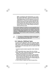
... SATA / SATAII / SATA3 driver diskette containing the Intel® RAID driver. After reading the floppy disk, the driver will be seamlessly upgraded to install a third-party RAID driver. Set up a "RAID Ready" system with a single SATA / SATAII / SATA3 hard disk. Begin Windows® setup by using "RAID Installation Guide" to set up system BIOS as step 2 of page 6. When prompted, insert the SATA / SATAII / SATA3 driver diskette containing the Intel® RAID driver. STEP 4: Install Windows® XP / XP 64-bit...
... SATA / SATAII / SATA3 driver diskette containing the Intel® RAID driver. After reading the floppy disk, the driver will be seamlessly upgraded to install a third-party RAID driver. Set up a "RAID Ready" system with a single SATA / SATAII / SATA3 hard disk. Begin Windows® setup by using "RAID Installation Guide" to set up system BIOS as step 2 of page 6. When prompted, insert the SATA / SATAII / SATA3 driver diskette containing the Intel® RAID driver. STEP 4: Install Windows® XP / XP 64-bit...
Intel Rapid Storage Guide
Page 13
... insert the disk labeled Manufacturer-supplied hardware support disk into Drive A:, insert ;a floppy disk containing the following steps to create the volume. 9. 7. Press Enter to install the Intel Rapid Storage Technology driver during text-mode phase). Use the up and down arrow keys to create a floppy disk with a screen asking you need to confirm your controller from the list of Windows XP* setup (during operating system setup: 1. Select 4: Exit and press Enter. 11. Press...
... insert the disk labeled Manufacturer-supplied hardware support disk into Drive A:, insert ;a floppy disk containing the following steps to create the volume. 9. 7. Press Enter to install the Intel Rapid Storage Technology driver during text-mode phase). Use the up and down arrow keys to create a floppy disk with a screen asking you need to confirm your controller from the list of Windows XP* setup (during operating system setup: 1. Select 4: Exit and press Enter. 11. Press...


