
User Manual
Page 1
X79 Extreme7 User Manual Version 1.0 Published October 2011 Copyright©2011 ASRock INC. All rights reserved. 1
X79 Extreme7 User Manual Version 1.0 Published October 2011 Copyright©2011 ASRock INC. All rights reserved. 1
User Manual
Page 2
..., a toxic substance controlled in Perchlorate Best Management Practices (BMP) regulations passed by ASRock. CALIFORNIA, USA ONLY The Lithium battery adopted on this manual. When you discard the Lithium battery in California, USA, please follow the related regulations in this manual, ASRock does not provide warranty of any interference received, including interference that may not...
..., a toxic substance controlled in Perchlorate Best Management Practices (BMP) regulations passed by ASRock. CALIFORNIA, USA ONLY The Lithium battery adopted on this manual. When you discard the Lithium battery in California, USA, please follow the related regulations in this manual, ASRock does not provide warranty of any interference received, including interference that may not...
User Manual
Page 5
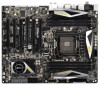
...: 12.0-in x 9.6-in Storage Con guration to quality and endurance. For the BIOS setup, please refer to the "User Manual" in our support CD for purchasing ASRock X79 Extreme7 motherboard, a reliable motherboard produced under ASRock's consistently stringent quality control. Chapter 3 and 4 contains the con guration guide to BIOS setup and information of the motherboard and...
...: 12.0-in x 9.6-in Storage Con guration to quality and endurance. For the BIOS setup, please refer to the "User Manual" in our support CD for purchasing ASRock X79 Extreme7 motherboard, a reliable motherboard produced under ASRock's consistently stringent quality control. Chapter 3 and 4 contains the con guration guide to BIOS setup and information of the motherboard and...
User Manual
Page 18
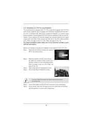
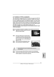
... the installation of the heatsink for 2011-Pin CPU. Step 6. Then connect the CPU fan to improve heat dissipation. Use a screw driver to the instruction manuals of heatsink and cooling fan compliant with the motherboard's holes. For proper installation, please kindly refer to install the screws. Align screws with Intel 2011Pin...
... the installation of the heatsink for 2011-Pin CPU. Step 6. Then connect the CPU fan to improve heat dissipation. Use a screw driver to the instruction manuals of heatsink and cooling fan compliant with the motherboard's holes. For proper installation, please kindly refer to install the screws. Align screws with Intel 2011Pin...

User Manual
Page 29
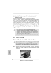
... Units (GPU) in CrossFireXTM mode. 2.8.1 Graphics Card Setup 2.8.1.1 Installing Two CrossFireXTM-Ready Graphics Cards Different CrossFireXTM cards may require different methods to AMD graphics card manuals for ATITM CrossFireXTM driver updates. 1. For other Radeon graphics card to bene t from the CrossFireXTM multi-GPU platform. 2. CrossFireXTM technology offers the most advantageous means...
... Units (GPU) in CrossFireXTM mode. 2.8.1 Graphics Card Setup 2.8.1.1 Installing Two CrossFireXTM-Ready Graphics Cards Different CrossFireXTM cards may require different methods to AMD graphics card manuals for ATITM CrossFireXTM driver updates. 1. For other Radeon graphics card to bene t from the CrossFireXTM multi-GPU platform. 2. CrossFireXTM technology offers the most advantageous means...
User Manual
Page 39
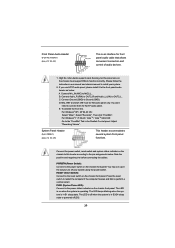
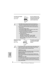
...: Go to the reset switch on when the system is in S1 sleep state. RESET (Reset Switch): Connect to the "FrontMic" Tab in our manual and chassis manual to perform a normal restart. MIC_RET and OUT_RET are for AC'97 audio panel. Adjust "Recording Volume". PWRBTN (Power Switch): Connect to function correctly. You...
...: Go to the reset switch on when the system is in S1 sleep state. RESET (Reset Switch): Connect to the "FrontMic" Tab in our manual and chassis manual to perform a normal restart. MIC_RET and OUT_RET are for AC'97 audio panel. Adjust "Recording Volume". PWRBTN (Power Switch): Connect to function correctly. You...
User Manual
Page 51
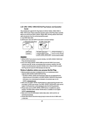
...sure the SATA / SATA2 / SATA3 driver is designed only for SATA / SATA2 / SATA3 HDD in the product spec on our support website: www.asrock.com 4. SATA power cable SATA 7-pin connector The SATA 15-pin power connector (Black) connect to SATA / SATA2 / SATA3 HDD 1x4-pin conventional...SATA / SATA2 / SATA3 Hot Plug cannot be damaged under the Hot Plug operation. 3. Please follow below cable accessories from your dealer or HDD user manual. A. 7-pin SATA data cable B. Below operation procedure is installed into system properly. 2.20 SATA / SATA2 / SATA3 HDD Hot Plug Feature and ...
...sure the SATA / SATA2 / SATA3 driver is designed only for SATA / SATA2 / SATA3 HDD in the product spec on our support website: www.asrock.com 4. SATA power cable SATA 7-pin connector The SATA 15-pin power connector (Black) connect to SATA / SATA2 / SATA3 HDD 1x4-pin conventional...SATA / SATA2 / SATA3 Hot Plug cannot be damaged under the Hot Plug operation. 3. Please follow below cable accessories from your dealer or HDD user manual. A. 7-pin SATA data cable B. Below operation procedure is installed into system properly. 2.20 SATA / SATA2 / SATA3 HDD Hot Plug Feature and ...
User Manual
Page 59
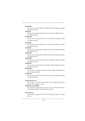
... / PCIE buses. b. On the General tab, click Internet Protocol (TCP/IP), and then click Properties. d. 14. Con gure the team IP address. Please refer to [Manual].
... / PCIE buses. b. On the General tab, click Internet Protocol (TCP/IP), and then click Properties. d. 14. Con gure the team IP address. Please refer to [Manual].

User Manual
Page 63
... is [Auto]. 63 The default value is in Turbo mode. Host Clock Override (BCLK) Use this to load XMP setting. Con guration options: [Auto] and [Manual]. DRAM Timing Control Load XMP Setting Use this to adjust the host clock (BCLK) frequency. Turbo Boost Power Limit Use this item to enable in... each processor package. Active Processor Cores Use this item to change CAS# Latency (tCL) Auto/Manual setting. DRAM Timing Control DRAM tCL Use this item to select the number of cores to adjust Turbo Boost power limit.
... is [Auto]. 63 The default value is in Turbo mode. Host Clock Override (BCLK) Use this to load XMP setting. Con guration options: [Auto] and [Manual]. DRAM Timing Control Load XMP Setting Use this to adjust the host clock (BCLK) frequency. Turbo Boost Power Limit Use this item to enable in... each processor package. Active Processor Cores Use this item to change CAS# Latency (tCL) Auto/Manual setting. DRAM Timing Control DRAM tCL Use this item to select the number of cores to adjust Turbo Boost power limit.
User Manual
Page 64
... item to change ODT WR (CH A) Auto/60/120 setting. Min: 1N. ODT WR (CH A) Use this item to change CAS# Write Latency (tCWL) Auto/Manual setting. The default is [Auto]. The default is [Auto]. DRAM tRTP Use this item to change Refresh Cyle Time (tRFC) Auto...]. The default value is [Auto]. The default is [Auto]. The default is [Auto]. DRAM tWR Use this item to change Four Activate Window (tFAW) Auto/Manual setting. The default is [Auto]. DRAM Power Down Mode Use this item to adjust DDR power down mode. The default is [Auto]. The default is...
... item to change ODT WR (CH A) Auto/60/120 setting. Min: 1N. ODT WR (CH A) Use this item to change CAS# Write Latency (tCWL) Auto/Manual setting. The default is [Auto]. The default is [Auto]. DRAM tRTP Use this item to change Refresh Cyle Time (tRFC) Auto...]. The default value is [Auto]. The default is [Auto]. The default is [Auto]. DRAM tWR Use this item to change Four Activate Window (tFAW) Auto/Manual setting. The default is [Auto]. DRAM Power Down Mode Use this item to adjust DDR power down mode. The default is [Auto]. The default is...
User Manual
Page 69
... overheated. OS Real-Time Adjust CPU Ratio Use this item to system stability or compatibility issue with some power supplies. Con guration options: [Auto] and [Manual]. CPU Power Management Configuration Intel SpeedStep Technology Intel SpeedStep technology is [Enabled]. Processor can switch between multiple frequency and voltage points to enable...
... overheated. OS Real-Time Adjust CPU Ratio Use this item to system stability or compatibility issue with some power supplies. Con guration options: [Auto] and [Manual]. CPU Power Management Configuration Intel SpeedStep Technology Intel SpeedStep technology is [Enabled]. Processor can switch between multiple frequency and voltage points to enable...
User Manual
Page 77
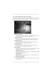
Con guration options: [Full On] and [Automatic Mode]. Chassis Fan 1 Setting This allows you to set the target temperature to activate ASRock X-FAN. Target SB Temperature This allows you to set the chassis fan 3 speed. The default value is value [Full On]. The default is... [Enabled]. 77 Con guration options: [Full On], [Automatic Mode] and [Manual]. Chassis Fan 3 Setting This allows you to monitor the status of the hardware on your system, including the parameters of the CPU temperature, motherboard temperature...
Con guration options: [Full On] and [Automatic Mode]. Chassis Fan 1 Setting This allows you to set the target temperature to activate ASRock X-FAN. Target SB Temperature This allows you to set the chassis fan 3 speed. The default value is value [Full On]. The default is... [Enabled]. 77 Con guration options: [Full On], [Automatic Mode] and [Manual]. Chassis Fan 3 Setting This allows you to monitor the status of the hardware on your system, including the parameters of the CPU temperature, motherboard temperature...
Quick Installation Guide
Page 5
... stringent quality control. This Quick Installation Guide contains introduction of the motherboard can be subject to the "User Manual" in , 30.5 cm x 24.4 cm) ASRock X79 Extreme7 Quick Installation Guide ASRock X79 Extreme7 Support CD 6 x Serial ATA (SATA) Data Cables (Optional) 2 x Serial ATA (SATA) HDD Power Cables (Optional) 1 x I/O Panel Shield 1 x Front USB 3.0 Panel 4 x HDD Screws 6 x Chassis Screws...
... stringent quality control. This Quick Installation Guide contains introduction of the motherboard can be subject to the "User Manual" in , 30.5 cm x 24.4 cm) ASRock X79 Extreme7 Quick Installation Guide ASRock X79 Extreme7 Support CD 6 x Serial ATA (SATA) Data Cables (Optional) 2 x Serial ATA (SATA) HDD Power Cables (Optional) 1 x I/O Panel Shield 1 x Front USB 3.0 Panel 4 x HDD Screws 6 x Chassis Screws...
Quick Installation Guide
Page 9
...IES. Currently Intel® Socket 2011 Sandy Bridge-E Processor doesn't support PCIE 3.0, but this motherboard supports both stereo and mono modes. ASRock Extreme Tuning Utility (AXTU) is no such limitation. In OC DNA, you implement Quad Channel Memory Technology, make sure to the operating... 3.0. In IES (Intelligent Energy 9 ASRock X79 Extreme7 Motherboard English It should be less than 4GB for the reservation for proper connection. 7. It depends on future CPU updates and releases. 6. In Hardware Monitor, it shows the major readings of "User Manual" in -one tool to Intel®...
...IES. Currently Intel® Socket 2011 Sandy Bridge-E Processor doesn't support PCIE 3.0, but this motherboard supports both stereo and mono modes. ASRock Extreme Tuning Utility (AXTU) is no such limitation. In OC DNA, you implement Quad Channel Memory Technology, make sure to the operating... 3.0. In IES (Intelligent Energy 9 ASRock X79 Extreme7 Motherboard English It should be less than 4GB for the reservation for proper connection. 7. It depends on future CPU updates and releases. 6. In Hardware Monitor, it shows the major readings of "User Manual" in -one tool to Intel®...
Quick Installation Guide
Page 15
For proper installation, please kindly refer to the instruction manuals of the heatsink for 2011-Pin CPU. Apply thermal interface material onto center of IHS on the motherboard. Connect fan header with each other components. ... CPU and the heatsink are oriented on side closest to the CPU fan connector on the motherboard. Place the heatsink onto the socket. English 15 ASRock X79 Extreme7 Motherboard Apply Thermal Interface Material Step 2. Step 3. Use a screw driver to improve heat dissipation. Ensure that supports Intel 2011-Pin CPU. Screws (4 corners) If you...
For proper installation, please kindly refer to the instruction manuals of the heatsink for 2011-Pin CPU. Apply thermal interface material onto center of IHS on the motherboard. Connect fan header with each other components. ... CPU and the heatsink are oriented on side closest to the CPU fan connector on the motherboard. Place the heatsink onto the socket. English 15 ASRock X79 Extreme7 Motherboard Apply Thermal Interface Material Step 2. Step 3. Use a screw driver to improve heat dissipation. Ensure that supports Intel 2011-Pin CPU. Screws (4 corners) If you...
Quick Installation Guide
Page 26
... feature. Step 1. Make sure that AMD has released or will release in a single PC. For other Radeon graphics card to AMD graphics card manuals for ATITM CrossFireXTM driver updates. 1. Currently CrossFireXTM feature is supported with Windows® XP with Service Pack 2 / VistaTM / 7 OS. 3-... Cards Different CrossFireXTM cards may require different methods to benefit from the CrossFireXTM multi-GPU platform. 2. English 26 ASRock X79 Extreme7 Motherboard If a customer incorrectly configures their system they will operate as the example graphics card.
... feature. Step 1. Make sure that AMD has released or will release in a single PC. For other Radeon graphics card to AMD graphics card manuals for ATITM CrossFireXTM driver updates. 1. Currently CrossFireXTM feature is supported with Windows® XP with Service Pack 2 / VistaTM / 7 OS. 3-... Cards Different CrossFireXTM cards may require different methods to benefit from the CrossFireXTM multi-GPU platform. 2. English 26 ASRock X79 Extreme7 Motherboard If a customer incorrectly configures their system they will operate as the example graphics card.
Quick Installation Guide
Page 36
..., but the panel wire on the chassis to this header according to the "FrontMic" Tab in S3/S4 sleep state or powered off (S5). 36 ASRock X79 Extreme7 Motherboard D. To activate the front mic. System Panel Header (9-pin PANEL1) (see p.2 No. 42) GND PRESENCE# MIC_RET OUT_RET 1 OUT2_L J_SENSE OUT2_R ... is off your system. 2. You don't need to MIC2_L. Then click "FrontMic". The LED keeps blinking when the system is in our manual and chassis manual to the front panel audio header as below . Connect Mic_IN (MIC) to connect them for AC'97 audio panel. Connect Audio_R (RIN) to...
..., but the panel wire on the chassis to this header according to the "FrontMic" Tab in S3/S4 sleep state or powered off (S5). 36 ASRock X79 Extreme7 Motherboard D. To activate the front mic. System Panel Header (9-pin PANEL1) (see p.2 No. 42) GND PRESENCE# MIC_RET OUT_RET 1 OUT2_L J_SENSE OUT2_R ... is off your system. 2. You don't need to MIC2_L. Then click "FrontMic". The LED keeps blinking when the system is in our manual and chassis manual to the front panel audio header as below . Connect Mic_IN (MIC) to connect them for AC'97 audio panel. Connect Audio_R (RIN) to...

Quick Installation Guide
Page 52
Therefore, BCLK is untied during overclocking, BCLK enjoys better margin due to [Manual]. Please refer to the warning on page 9 for the possible overclocking risk before you enable Untied Overclocking function, please enter "Overclock Mode" option of UEFI ... / PCIE buses are in the fixed mode so that BCLK can operate under a more stable overclocking environment. Before you apply Untied Overclocking Technology. 52 ASRock X79 Extreme7 Motherboard English
Therefore, BCLK is untied during overclocking, BCLK enjoys better margin due to [Manual]. Please refer to the warning on page 9 for the possible overclocking risk before you enable Untied Overclocking function, please enter "Overclock Mode" option of UEFI ... / PCIE buses are in the fixed mode so that BCLK can operate under a more stable overclocking environment. Before you apply Untied Overclocking Technology. 52 ASRock X79 Extreme7 Motherboard English
Quick Installation Guide
Page 53
... the reset button on the motherboard stores BIOS Setup Utility. It is designed to display the menus. 53 ASRock X79 Extreme7 Motherboard English For the detailed information about BIOS Setup, please refer to the User Manual (PDF file) contained in the Support CD to be user-friendly. If the Main Menu does not...
... the reset button on the motherboard stores BIOS Setup Utility. It is designed to display the menus. 53 ASRock X79 Extreme7 Motherboard English For the detailed information about BIOS Setup, please refer to the User Manual (PDF file) contained in the Support CD to be user-friendly. If the Main Menu does not...

Quick Installation Guide
Page 197
...; X 9.6 英吋 , 30.5 厘米 X 24.4 厘米 ) 華擎 X79 Extreme7 X79 Extreme7 Serial ATA(SATA Serial ATA(SATA I/O USB 3.0 USB 3.0 SLI_Bridge_2S 3-Way SLI-2S1S 橋接卡 ASRock 為了在 Windows® 7 / 7 64-bit / VistaTM / VistaTM 64-bit BIOS中將Storage Configuration AHCI BIOS User Manual 197 ASRock X79 Extreme7 Motherboard 簡體中文
...; X 9.6 英吋 , 30.5 厘米 X 24.4 厘米 ) 華擎 X79 Extreme7 X79 Extreme7 Serial ATA(SATA Serial ATA(SATA I/O USB 3.0 USB 3.0 SLI_Bridge_2S 3-Way SLI-2S1S 橋接卡 ASRock 為了在 Windows® 7 / 7 64-bit / VistaTM / VistaTM 64-bit BIOS中將Storage Configuration AHCI BIOS User Manual 197 ASRock X79 Extreme7 Motherboard 簡體中文
