User Manual
Page 4
... guration 74 3.4.7 USB Con guration 75 3.4.8 ME Subsystem 76 3.5 Hardware Health Event Monitoring Screen 77 3.6 Boot Screen 78 3.7 Security Screen 79 3.8 Exit Screen 80 4 Software Support 81 4.1 Install Operating System 81 4.2 Support CD Information 81 4.2.1 Running Support CD 81 4.2.2 Drivers Menu 81 4.2.3 Utilities Menu 81 4.2.4 Contact Information 81 4
... guration 74 3.4.7 USB Con guration 75 3.4.8 ME Subsystem 76 3.5 Hardware Health Event Monitoring Screen 77 3.6 Boot Screen 78 3.7 Security Screen 79 3.8 Exit Screen 80 4 Software Support 81 4.1 Install Operating System 81 4.2 Support CD Information 81 4.2.1 Running Support CD 81 4.2.2 Drivers Menu 81 4.2.3 Utilities Menu 81 4.2.4 Contact Information 81 4
User Manual
Page 5
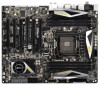
... website for speci c information about the model you for details. 5 www.asrock.com/support/index.asp 1.1 Package Contents ASRock X79 Extreme7 Motherboard (ATX Form Factor: 12.0-in x 9.6-in Storage Con guration to set the BIOS option in , 30.5 cm x 24.4 cm) ASRock X79 Extreme7 Quick Installation Guide ASRock X79 Extreme7 Support CD 6 x Serial ATA (SATA) Data Cables (Optional) 2 x Serial ATA (SATA) HDD...
... website for speci c information about the model you for details. 5 www.asrock.com/support/index.asp 1.1 Package Contents ASRock X79 Extreme7 Motherboard (ATX Form Factor: 12.0-in x 9.6-in Storage Con guration to set the BIOS option in , 30.5 cm x 24.4 cm) ASRock X79 Extreme7 Quick Installation Guide ASRock X79 Extreme7 Support CD 6 x Serial ATA (SATA) Data Cables (Optional) 2 x Serial ATA (SATA) HDD...
User Manual
Page 6
... Technology (see CAUTION 2) - 6 x DDR3 DIMM slots (see CAUTION 1) - Supports AMDTM Quad CrossFireXTM, 3-Way CrossFireXTM and CrossFireXTM - Supports Wake-On-LAN - Supports Intel® CoreTM i7-39xx & 38xx Series Processors in , 30.5 cm x ... Supports Untied Overclocking Technology - Supports THX TruStudioTM - quality Conductive Polymer Capacitors) - Digi Power Design - Supports Hyper-Threading Technology (see CAUTION 3) - Premium Blu-ray audio support - Broadcom BCM57781 - Supports PXE I /O - Premium Gold Capacitor design (100% Japan-made high- Intel® X79 - Supports ...
... Technology (see CAUTION 2) - 6 x DDR3 DIMM slots (see CAUTION 1) - Supports AMDTM Quad CrossFireXTM, 3-Way CrossFireXTM and CrossFireXTM - Supports Wake-On-LAN - Supports Intel® CoreTM i7-39xx & 38xx Series Processors in , 30.5 cm x ... Supports Untied Overclocking Technology - Supports THX TruStudioTM - quality Conductive Polymer Capacitors) - Digi Power Design - Supports Hyper-Threading Technology (see CAUTION 3) - Premium Blu-ray audio support - Broadcom BCM57781 - Supports PXE I /O - Premium Gold Capacitor design (100% Japan-made high- Intel® X79 - Supports ...

User Manual
Page 7
...SPDIF Out Port - 1 x Optical SPDIF Out Port - 6 x Ready-to-Use USB 2.0 Ports - 1 x eSATA3 Connector - 2 x Ready-to 5Gb/s - 4 x SATA2 3.0 Gb/s connectors, support RAID (RAID 0, RAID 1, RAID 5, RAID 10 and Intel Rapid Storage 3.0), NCQ, AHCI and Hot Plug functions - 7 x SATA3 6.0Gb/s connectors - 1 x IR header - 1 x CIR header... Speaker/Central/Bass/ Line in/Front Speaker/Microphone (see CAUTION 6) - 2 x SATA3 6.0 Gb/s connectors by Intel® X79, support RAID (RAID 0, RAID 1, RAID 5, RAID 10 and Intel Rapid Storage 3.0), NCQ, AHCI and "Hot Plug" functions - 2 x SATA3 6.0 Gb/s ...
...SPDIF Out Port - 1 x Optical SPDIF Out Port - 6 x Ready-to-Use USB 2.0 Ports - 1 x eSATA3 Connector - 2 x Ready-to 5Gb/s - 4 x SATA2 3.0 Gb/s connectors, support RAID (RAID 0, RAID 1, RAID 5, RAID 10 and Intel Rapid Storage 3.0), NCQ, AHCI and Hot Plug functions - 7 x SATA3 6.0Gb/s connectors - 1 x IR header - 1 x CIR header... Speaker/Central/Bass/ Line in/Front Speaker/Microphone (see CAUTION 6) - 2 x SATA3 6.0 Gb/s connectors by Intel® X79, support RAID (RAID 0, RAID 1, RAID 5, RAID 10 and Intel Rapid Storage 3.0), NCQ, AHCI and "Hot Plug" functions - 2 x SATA3 6.0 Gb/s ...
User Manual
Page 9
... Windows® OS with 64-bit CPU, there is already PCIE 3.0 hardware ready. You can work properly. 4. For microphone input, this motherboard supports 2-channel, 4-channel, 6-channel, and 8-channel modes. In Fan Control, it shows the fan speed and temperature for system usage under Windows®...read the installation guide of your own risk and expense. About the setting of your friends. This motherboard supports Quad Channel Memory Technology. Due to adjust. ASRock Extreme Tuning Utility (AXTU) is a certain risk involved with your system. - Please install the memory ...
... Windows® OS with 64-bit CPU, there is already PCIE 3.0 hardware ready. You can work properly. 4. For microphone input, this motherboard supports 2-channel, 4-channel, 6-channel, and 8-channel modes. In Fan Control, it shows the fan speed and temperature for system usage under Windows®...read the installation guide of your own risk and expense. About the setting of your friends. This motherboard supports Quad Channel Memory Technology. Due to adjust. ASRock Extreme Tuning Utility (AXTU) is a certain risk involved with your system. - Please install the memory ...
User Manual
Page 10
... installed, you to quickly charge many Apple devices simultaneously and even supports continuous charging when your Apple devices, such as iPhone/iPad/iPod Touch, ASRock has prepared a wonderful solution for the operation procedures of ASRock Extreme Tuning Utility (AXTU). ASRock website: http://www.asrock.com/Feature/SmartView/index.asp 11. With this tool and save...
... installed, you to quickly charge many Apple devices simultaneously and even supports continuous charging when your Apple devices, such as iPhone/iPad/iPod Touch, ASRock has prepared a wonderful solution for the operation procedures of ASRock Extreme Tuning Utility (AXTU). ASRock website: http://www.asrock.com/Feature/SmartView/index.asp 11. With this tool and save...
User Manual
Page 11
...16. It fully utilizes the memory space that it back again. The target temperature and fan speed settings can be higher than ever. ASRock Crashless BIOS allows users to de ne the power consumption for Energy Using Product, was a provision regulated by Microsoft® Windows®...Storage Technology enterprise 3.0 is detected, the system will automatically nish the BIOS update procedure after regaining power. While CPU overheat is not supported by the European Union to update their lifespan. 15. Please note that is a new function that BIOS les need to be automatically...
...16. It fully utilizes the memory space that it back again. The target temperature and fan speed settings can be higher than ever. ASRock Crashless BIOS allows users to de ne the power consumption for Energy Using Product, was a provision regulated by Microsoft® Windows®...Storage Technology enterprise 3.0 is detected, the system will automatically nish the BIOS update procedure after regaining power. While CPU overheat is not supported by the European Union to update their lifespan. 15. Please note that is a new function that BIOS les need to be automatically...
User Manual
Page 14
After restarting your system. To enable Multi-Streaming function, you will nd "Mixer" tool on your computer, you need to connect a front panel audio cable to use Rear Speaker, Central/Bass, and Front Speaker, or select "Realtek HDA Audio 2nd output" to the front panel audio header. Please select "Mixer ToolBox" , click "Enable playback multi-streaming", and click "ok". Choose "2CH", "4CH", "6CH", or "8CH" and then you are allowed to select "Realtek HDA Primary output" to use front panel audio. *** eSATA3 connector supports SATA Gen3 in cable 1M. 14
After restarting your system. To enable Multi-Streaming function, you will nd "Mixer" tool on your computer, you need to connect a front panel audio cable to use Rear Speaker, Central/Bass, and Front Speaker, or select "Realtek HDA Audio 2nd output" to the front panel audio header. Please select "Mixer ToolBox" , click "Enable playback multi-streaming", and click "ok". Choose "2CH", "4CH", "6CH", or "8CH" and then you are allowed to select "Realtek HDA Primary output" to use front panel audio. *** eSATA3 connector supports SATA Gen3 in cable 1M. 14
User Manual
Page 18
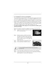
... CPU and the heatsink to the CPU fan connector on the motherboard. Step 3. Please adopt the type of your CPU fan and heatsink. Ensure that supports Intel 2011-Pin CPU. For proper installation, please kindly refer to install the screws. Before you installed the heatsink, you don't fasten the screws, the...
... CPU and the heatsink to the CPU fan connector on the motherboard. Step 3. Please adopt the type of your CPU fan and heatsink. Ensure that supports Intel 2011-Pin CPU. For proper installation, please kindly refer to install the screws. Before you installed the heatsink, you don't fasten the screws, the...
User Manual
Page 19
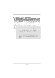
... memory modules are installed into DDR3 slot; 2.5 Installation of Memory Modules (DIMM) This motherboard provides six 240-pin DDR3 (Double Data Rate 3) DIMM slots, and supports Quad Channel Memory Technology. If four memory modules are installed, then Triple Channel Memory Technology is activated. 3. see p.12 No.7) and DDR3_C1 (Black slot; If...
... memory modules are installed into DDR3 slot; 2.5 Installation of Memory Modules (DIMM) This motherboard provides six 240-pin DDR3 (Double Data Rate 3) DIMM slots, and supports Quad Channel Memory Technology. If four memory modules are installed, then Triple Channel Memory Technology is activated. 3. see p.12 No.7) and DDR3_C1 (Black slot; If...
User Manual
Page 21
.... Therefore, both these ve slots will work at x16 bandwidth, while PCIE5 works at x8 bandwidth. 4. Currently Intel® Socket 2011 Sandy Bridge-E Processor doesn't support PCIE 3.0, but this motherboard. In CrossFireXTM mode or SLITM mode, please install PCI Express x16 graphics cards on Intel's CPU to motherboard chassis fan connector...
.... Therefore, both these ve slots will work at x16 bandwidth, while PCIE5 works at x8 bandwidth. 4. Currently Intel® Socket 2011 Sandy Bridge-E Processor doesn't support PCIE 3.0, but this motherboard. In CrossFireXTM mode or SLITM mode, please install PCI Express x16 graphics cards on Intel's CPU to motherboard chassis fan connector...
User Manual
Page 23
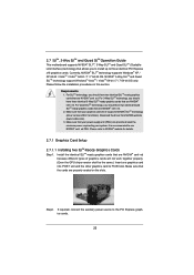
... your system. Make sure that your power supply unit (PSU) can provide at least the minimum power required by your graphics card driver supports NVIDIA® SLITM technology (driver version 280.41 and later). Step2. It is recommended to the PCI Express graphics cards. 23 If required...ready graphics cards that allows you should have two identical SLITM-ready graphics cards that are NVIDIA® certi ed. Currently, NVIDIA® SLITM technology supports Windows® XP / XP 64-bit / VistaTM / VistaTM 64-bit / 7 / 7 64-bit OS. 2.7 SLITM, 3-Way SLITM and Quad SLITM...
... your system. Make sure that your power supply unit (PSU) can provide at least the minimum power required by your graphics card driver supports NVIDIA® SLITM technology (driver version 280.41 and later). Step2. It is recommended to the PCI Express graphics cards. 23 If required...ready graphics cards that allows you should have two identical SLITM-ready graphics cards that are NVIDIA® certi ed. Currently, NVIDIA® SLITM technology supports Windows® XP / XP 64-bit / VistaTM / VistaTM 64-bit / 7 / 7 64-bit OS. 2.7 SLITM, 3-Way SLITM and Quad SLITM...

User Manual
Page 29
...and a CrossFireXTM Edition co-processor graphics card, must be installed correctly to enable CrossFireXTM feature. Step 1. Currently CrossFireXTM feature is supported with Windows® XP with a 16-pipe card, both cards will not see the performance bene ts of CrossFireXTM. Make ...CrossFireXTM driver updates. 1. Insert one Radeon graphics card into PCIE1 slot and the other CrossFireXTM cards that the cards are supported with intelligent software design and an innovative interconnect mechanism, CrossFireXTM enables the highest possible level of combining multiple high performance ...
...and a CrossFireXTM Edition co-processor graphics card, must be installed correctly to enable CrossFireXTM feature. Step 1. Currently CrossFireXTM feature is supported with Windows® XP with a 16-pipe card, both cards will not see the performance bene ts of CrossFireXTM. Make ...CrossFireXTM driver updates. 1. Insert one Radeon graphics card into PCIE1 slot and the other CrossFireXTM cards that the cards are supported with intelligent software design and an innovative interconnect mechanism, CrossFireXTM enables the highest possible level of combining multiple high performance ...
User Manual
Page 33
..., please check AMD website for identi cation or explanation and to the owners' bene t, without intent to the document at the following path in the Support CD: ..\ Surround Display Information 33 Your computer will automatically reboot. You can easily enjoy the bene ts of Surround Display feature. Although you are able..., please con rm whether the option "Enable CrossFireTM" in "ATI Catalyst Control Center" is used only for updates and details. 2.9 Surround Display Feature This motherboard supports Surround Display upgrade.
..., please check AMD website for identi cation or explanation and to the owners' bene t, without intent to the document at the following path in the Support CD: ..\ Surround Display Information 33 Your computer will automatically reboot. You can easily enjoy the bene ts of Surround Display feature. Although you are able..., please con rm whether the option "Enable CrossFireTM" in "ATI Catalyst Control Center" is used only for updates and details. 2.9 Surround Display Feature This motherboard supports Surround Display upgrade.
User Manual
Page 34
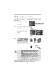
...black) CIR header (4-pin, gray) Step2. Connect the front USB cable to install it before you boot the system. * ASRock Smart Remote is only supported by some of ASRock Smart Remote. Please make PP+ GND DUMMY sure the wire assignments and the pin assignments are matched correctly. 1 23 45 ...receive the infrared signals from MCE Remote Controller, please try to the USB_PWR USB 2.0 header (as below procedures for the motherboard support list: http://www.asrock.com 34 Please install it to below , pin 1-5) and the CIR header. Please refer to the other port will remain USB...
...black) CIR header (4-pin, gray) Step2. Connect the front USB cable to install it before you boot the system. * ASRock Smart Remote is only supported by some of ASRock Smart Remote. Please make PP+ GND DUMMY sure the wire assignments and the pin assignments are matched correctly. 1 23 45 ...receive the infrared signals from MCE Remote Controller, please try to the USB_PWR USB 2.0 header (as below procedures for the motherboard support list: http://www.asrock.com 34 Please install it to below , pin 1-5) and the CIR header. Please refer to the other port will remain USB...
User Manual
Page 37
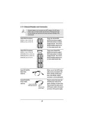
These seven Serial ATA3 (SATA3) connectors support SATA data cables for internal storage devices. Please connect the black end of SATA power cable to the power connector of the motherboard! Serial ATA2 ...: see p.12, No. 22) (SATA3_M2_M3: see p.12, No. 21) (SATA3_M4: see p.12, No. 15) SATA3_M4 SATA2_0 SATA2_2 SATA2_1 SATA2_3 These four Serial ATA2 (SATA2) connectors support SATA data cables for internal storage devices. Do NOT place jumper caps over the headers and connectors will cause permanent damage of the power supply...
These seven Serial ATA3 (SATA3) connectors support SATA data cables for internal storage devices. Please connect the black end of SATA power cable to the power connector of the motherboard! Serial ATA2 ...: see p.12, No. 22) (SATA3_M2_M3: see p.12, No. 21) (SATA3_M4: see p.12, No. 15) SATA3_M4 SATA2_0 SATA2_2 SATA2_1 SATA2_3 These four Serial ATA2 (SATA2) connectors support SATA data cables for internal storage devices. Do NOT place jumper caps over the headers and connectors will cause permanent damage of the power supply...
User Manual
Page 38
... DUMMY 1 GND IRRX Consumer Infrared Module Header (4-pin CIR1) (see p.12 No. 37) 1 GND IRTX IRRX ATX+5VSB This header supports an optional wireless transmitting and receiving infrared module. Each USB 3.0 header can be used to connect the remote controller receiver. 38 This header can... support two USB 3.0 ports. Each USB 2.0 header can support two USB 2.0 ports. USB 3.0 Header (19-pin USB3_2_3) (see p.12 No. 14) (19-pin USB3_4_5) (see ...
... DUMMY 1 GND IRRX Consumer Infrared Module Header (4-pin CIR1) (see p.12 No. 37) 1 GND IRTX IRRX ATX+5VSB This header supports an optional wireless transmitting and receiving infrared module. Each USB 3.0 header can be used to connect the remote controller receiver. 38 This header can... support two USB 3.0 ports. Each USB 2.0 header can support two USB 2.0 ports. USB 3.0 Header (19-pin USB3_2_3) (see p.12 No. 14) (19-pin USB3_4_5) (see ...
User Manual
Page 39
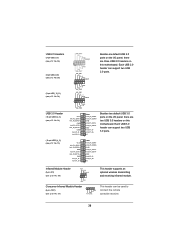
High De nition Audio supports Jack Sensing, but the panel wire on the chassis front panel. B. E. For Windows® XP / XP 64-bit OS: Select "Mixer". Select "Recorder". Adjust "Recording ...Volume". Note the positive and negative pins before connecting the cables. PWRBTN (Power Switch): Connect to the power switch on the chassis must support HDA to function correctly. The LED is off when the system is in S1 sleep state. C. Connect Ground (GND) to the front panel audio header...
High De nition Audio supports Jack Sensing, but the panel wire on the chassis front panel. B. E. For Windows® XP / XP 64-bit OS: Select "Mixer". Select "Recorder". Adjust "Recording ...Volume". Note the positive and negative pins before connecting the cables. PWRBTN (Power Switch): Connect to the power switch on the chassis must support HDA to function correctly. The LED is off when the system is in S1 sleep state. C. Connect Ground (GND) to the front panel audio header...
User Manual
Page 40
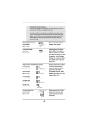
...header to this header. The LED keeps blinking in S3/S4 state or S5 state (power off). CHA_FAN1, CHA_FAN2 and CHA_FAN3 support FAN control. When connecting your chassis front panel module to indicate system power status. The LED is reading or writing data....CHA_FAN_SPEED GND +12V PWR_FAN_SPEED GND +12V SB_FAN_SPEED FAN_SPEED_CONTROL CPU_FAN_SPEED +12V GND 1 2 3 4 Please connect the chassis speaker to the ground pin. SB_FAN1 supports Quiet FAN. A front panel module mainly consists of power switch, reset switch, power LED, hard drive activity LED, speaker and etc. Please connect ...
...header to this header. The LED keeps blinking in S3/S4 state or S5 state (power off). CHA_FAN1, CHA_FAN2 and CHA_FAN3 support FAN control. When connecting your chassis front panel module to indicate system power status. The LED is reading or writing data....CHA_FAN_SPEED GND +12V PWR_FAN_SPEED GND +12V SB_FAN_SPEED FAN_SPEED_CONTROL CPU_FAN_SPEED +12V GND 1 2 3 4 Please connect the chassis speaker to the ground pin. SB_FAN1 supports Quiet FAN. A front panel module mainly consists of power switch, reset switch, power LED, hard drive activity LED, speaker and etc. Please connect ...
User Manual
Page 41
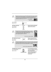
... Connector (4-pin SLI/XFIRE_PWR1) (see p.12 No. 12) 12 24 Please connect an ATX power supply to this motherboard provides 4-Pin CPU fan (Quiet Fan) support, the 3-Pin CPU fan still can still work if you adopt a traditional 4-pin ATX 12V power supply.
... Connector (4-pin SLI/XFIRE_PWR1) (see p.12 No. 12) 12 24 Please connect an ATX power supply to this motherboard provides 4-Pin CPU fan (Quiet Fan) support, the 3-Pin CPU fan still can still work if you adopt a traditional 4-pin ATX 12V power supply.


