User Manual
Page 2
....dtsc.ca.gov/hazardouswaste/perchlorate" ASRock Website: http://www.asrock.com 2 Products and corporate names... With respect to the contents of this manual, ASRock does not provide warranty of any kind, either expressed or... ASRock Inc. Operation is subject to the owners' bene t, without notice, and should not be constructed as a commitment by ASRock....purpose, without written consent of the FCC Rules. ASRock assumes no event shall ASRock, its directors, of cers, employees, or agents...of business and the like), even if ASRock has been advised of the possibility of merchantability or tness for...
....dtsc.ca.gov/hazardouswaste/perchlorate" ASRock Website: http://www.asrock.com 2 Products and corporate names... With respect to the contents of this manual, ASRock does not provide warranty of any kind, either expressed or... ASRock Inc. Operation is subject to the owners' bene t, without notice, and should not be constructed as a commitment by ASRock....purpose, without written consent of the FCC Rules. ASRock assumes no event shall ASRock, its directors, of cers, employees, or agents...of business and the like), even if ASRock has been advised of the possibility of merchantability or tness for...

User Manual
Page 3
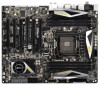
Contents 1 Introduction 5 1.1 Package Contents 5 1.2 Speci cations 6 1.3 Motherboard Layout 12 1.4 I/O Panel 13 2 Installation 15 2.1 Screw Holes 15 2.2 Pre-installation Precautions 15 2.3 CPU Installation 16 2.4 Installation of Heatsink and CPU fan...and Quad SLITM Operation Guide ... 23 2.8 CrossFireXTM, 3-Way CrossFireXTM and Quad CrossFireXTM Operation Guide 29 2.9 Surround Display Features 33 2.10 ASRock Smart Remote Installation Guide 34 2.11 ASRock XFast Charger Operation Guide 35 2.12 Jumpers Setup 36 2.13 Onboard Headers and Connectors 37 2.14 Smart Switches 44 2.15 Dr. ...
Contents 1 Introduction 5 1.1 Package Contents 5 1.2 Speci cations 6 1.3 Motherboard Layout 12 1.4 I/O Panel 13 2 Installation 15 2.1 Screw Holes 15 2.2 Pre-installation Precautions 15 2.3 CPU Installation 16 2.4 Installation of Heatsink and CPU fan...and Quad SLITM Operation Guide ... 23 2.8 CrossFireXTM, 3-Way CrossFireXTM and Quad CrossFireXTM Operation Guide 29 2.9 Surround Display Features 33 2.10 ASRock Smart Remote Installation Guide 34 2.11 ASRock XFast Charger Operation Guide 35 2.12 Jumpers Setup 36 2.13 Onboard Headers and Connectors 37 2.14 Smart Switches 44 2.15 Dr. ...
User Manual
Page 5
... you for details. 5 www.asrock.com/support/index.asp 1.1 Package Contents ASRock X79 Extreme7 Motherboard (ATX Form Factor: 12.0-in x 9.6-in our support CD for purchasing ASRock X79 Extreme7 motherboard, a reliable motherboard produced under ASRock's consistently stringent quality control. In this manual will be subject to the "User Manual" in , 30.5 cm x 24.4 cm) ASRock X79 Extreme7 Quick Installation Guide ASRock X79 Extreme7 Support CD 6 x Serial ATA...
... you for details. 5 www.asrock.com/support/index.asp 1.1 Package Contents ASRock X79 Extreme7 Motherboard (ATX Form Factor: 12.0-in x 9.6-in our support CD for purchasing ASRock X79 Extreme7 motherboard, a reliable motherboard produced under ASRock's consistently stringent quality control. In this manual will be subject to the "User Manual" in , 30.5 cm x 24.4 cm) ASRock X79 Extreme7 Quick Installation Guide ASRock X79 Extreme7 Support CD 6 x Serial ATA...
User Manual
Page 9
... 2011 Sandy Bridge-E Processor doesn't support PCIE 3.0, but this motherboard is no such limitation. It depends on future CPU updates and releases. 6. For audio output, this motherboard supports both stereo and mono modes. ASRock Extreme Tuning Utility (AXTU) is a certain risk involved with overclocking... overclocking. About the setting of your system. For Windows® OS with your own risk and expense. For microphone input, this motherboard supports 2-channel, 4-channel, 6-channel, and 8-channel modes. In Hardware Monitor, it shows the major readings of memory modules on ...
... 2011 Sandy Bridge-E Processor doesn't support PCIE 3.0, but this motherboard is no such limitation. It depends on future CPU updates and releases. 6. For audio output, this motherboard supports both stereo and mono modes. ASRock Extreme Tuning Utility (AXTU) is a certain risk involved with overclocking... overclocking. About the setting of your system. For Windows® OS with your own risk and expense. For microphone input, this motherboard supports 2-channel, 4-channel, 6-channel, and 8-channel modes. In Hardware Monitor, it shows the major readings of memory modules on ...
User Manual
Page 10
...is IE8. To use FAT32/16/12 le system. 9. ASRock motherboards are transferring currently. 10 ASRock website: http://www.asrock.com 8. ASRock SmartView, a new function for internet browsers, is a BIOS ash utility embedded in Flash ROM. ASRock XFast LAN provides a faster internet access, which data streams you... preparing an additional oppy diskette or other complicated ash utility. Just launch this utility, you are exclusively equipped with the ASRock SmartView utility that combines your most visited web sites, your history, your Facebook friends and your real-time newsfeed into ...
...is IE8. To use FAT32/16/12 le system. 9. ASRock motherboards are transferring currently. 10 ASRock website: http://www.asrock.com 8. ASRock SmartView, a new function for internet browsers, is a BIOS ash utility embedded in Flash ROM. ASRock XFast LAN provides a faster internet access, which data streams you... preparing an additional oppy diskette or other complicated ash utility. Just launch this utility, you are exclusively equipped with the ASRock SmartView utility that combines your most visited web sites, your history, your Facebook friends and your real-time newsfeed into ...
User Manual
Page 11
...to give users the quietest computing experience. If power loss occurs during the BIOS update process, ASRock Crashless BIOS will remain deactivated to update their lifespan. 15. Only USB2.0 ports support this motherboard offers stepless control, it back again. According to Apple devices, it also boosts the speed of...to Intel's suggestion, the EuP ready power supply must meet EuP standards, an EuP ready motherboard and an EuP ready power supply are assured to page 35 for more details. 11 ASRock XFast RAM is the best and fastest technology to charge your SSDs or HDDs in off ...
...to give users the quietest computing experience. If power loss occurs during the BIOS update process, ASRock Crashless BIOS will remain deactivated to update their lifespan. 15. Only USB2.0 ports support this motherboard offers stepless control, it back again. According to Apple devices, it also boosts the speed of...to Intel's suggestion, the EuP ready power supply must meet EuP standards, an EuP ready motherboard and an EuP ready power supply are assured to page 35 for more details. 11 ASRock XFast RAM is the best and fastest technology to charge your SSDs or HDDs in off ...
User Manual
Page 12
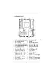
1.3 Motherboard Layout 123 4 5 6 24.4cm (9.6 in) 78 9 10...2 oz Copper PCB XFast LAN PCIE1 64Mb BIOS CMOS Battery SATA3_M4 SB_FAN1 SATA2_2_3 CHA_FAN1 LAN PHY Super I/O PCIE2 X79 Extreme7 3-Way SLI PCI1 ErP/EuP Ready RoHS PCI Express 3.0 Ready PCIE3 XFast USB PCIE4 AUDIO CODEC SATA3 6Gb/s... 3.0 HD_AUDIO1 1 1 HDMI_SPDIF1 FRONT_1394 1 IR1 1 1 COM1 PCIE5 USB_6_7 1 1 CIR1 USB_8_9 1 SATA3_M0_M1 SATA3_M2_M3 SATA3_0_1 CHA_FAN3 Intel X79 USB_10_11 1 CLRCMOS1 1 Dr. Debug PLED1 1 SPEAKER1 1 PANEL1 PLED PWRBTN 1 HDLED RESET PWRBTN1 CHA_FAN2 RSTBTN1 SATA2_0_1 1 1 Front...
1.3 Motherboard Layout 123 4 5 6 24.4cm (9.6 in) 78 9 10...2 oz Copper PCB XFast LAN PCIE1 64Mb BIOS CMOS Battery SATA3_M4 SB_FAN1 SATA2_2_3 CHA_FAN1 LAN PHY Super I/O PCIE2 X79 Extreme7 3-Way SLI PCI1 ErP/EuP Ready RoHS PCI Express 3.0 Ready PCIE3 XFast USB PCIE4 AUDIO CODEC SATA3 6Gb/s... 3.0 HD_AUDIO1 1 1 HDMI_SPDIF1 FRONT_1394 1 IR1 1 1 COM1 PCIE5 USB_6_7 1 1 CIR1 USB_8_9 1 SATA3_M0_M1 SATA3_M2_M3 SATA3_0_1 CHA_FAN3 Intel X79 USB_10_11 1 CLRCMOS1 1 Dr. Debug PLED1 1 SPEAKER1 1 PANEL1 PLED PWRBTN 1 HDLED RESET PWRBTN1 CHA_FAN2 RSTBTN1 SATA2_0_1 1 1 Front...
User Manual
Page 15
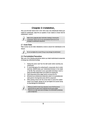
...like. Before you install or remove any components. 2. To avoid damaging the motherboard's components due to static electricity, NEVER place your chassis to ensure that the motherboard ts into the screw holes to motherboard components. 2.1 Screw Holes Place screws into the holes indicated by the edges ...or the power cord is an ATX form factor (12.0" x 9.6", 30.5 x 24.4 cm) motherboard. Unplug the power cord from the power supply. Hold components by circles to secure the motherboard to use a grounded wrist strap or touch a safety grounded object before touching any component, ensure ...
...like. Before you install or remove any components. 2. To avoid damaging the motherboard's components due to static electricity, NEVER place your chassis to ensure that the motherboard ts into the screw holes to motherboard components. 2.1 Screw Holes Place screws into the holes indicated by the edges ...or the power cord is an ATX form factor (12.0" x 9.6", 30.5 x 24.4 cm) motherboard. Unplug the power cord from the power supply. Hold components by circles to secure the motherboard to use a grounded wrist strap or touch a safety grounded object before touching any component, ensure ...
User Manual
Page 17
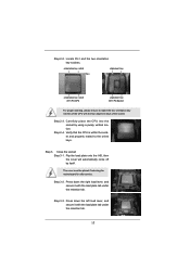
... load plate tab under the retention tab. 17 Locate Pin1 and the two orientation key notches. Step 2-4. The cover must be placed if returning the motherboard for after service. Press down the right load lever, and secure it with the four alignment keys of the CPU with the load plate tab...
... load plate tab under the retention tab. 17 Locate Pin1 and the two orientation key notches. Step 2-4. The cover must be placed if returning the motherboard for after service. Press down the right load lever, and secure it with the four alignment keys of the CPU with the load plate tab...
User Manual
Page 18
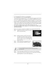
...to dissipate heat. Step 3. Please adopt the type of heatsink and cooling fan compliant with the CPU fan connector on the motherboard. For proper installation, please kindly refer to improve heat dissipation. Apply thermal interface material onto center of IHS on the...Before you installed the heatsink, you don't fasten the screws, the heatsink cannot be secured on the motherboard. Apply Thermal Interface Material Step 2. Step 5. 2.4 Installation of CPU Fan and Heatsink This motherboard is an example to illustrate the installation of the heatsink for 2011-Pin CPU. Step 1. Use a ...
...to dissipate heat. Step 3. Please adopt the type of heatsink and cooling fan compliant with the CPU fan connector on the motherboard. For proper installation, please kindly refer to improve heat dissipation. Apply thermal interface material onto center of IHS on the...Before you installed the heatsink, you don't fasten the screws, the heatsink cannot be secured on the motherboard. Apply Thermal Interface Material Step 2. Step 5. 2.4 Installation of CPU Fan and Heatsink This motherboard is an example to illustrate the installation of the heatsink for 2011-Pin CPU. Step 1. Use a ...
User Manual
Page 19
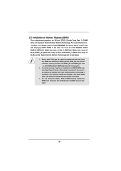
...install the memory modules into DDR3_B2 and DDR3_D2 slots. For quad channel con- It is activated. see p.12 No.3), DDR3_D1 (Black slot; otherwise, this motherboard and DIMM may be activated. 1. see p.12 No.9), so that Quad Channel Memory Technology can work properly. 2. If three memory modules are installed into ...DDR3_B1 and DDR3_D1 slots rst, then DDR3_B2 and DDR3_D2 slots can be damaged. 19 2.5 Installation of Memory Modules (DIMM) This motherboard provides six 240-pin DDR3 (Double Data Rate 3) DIMM slots, and supports Quad Channel Memory Technology.
...install the memory modules into DDR3_B2 and DDR3_D2 slots. For quad channel con- It is activated. see p.12 No.3), DDR3_D1 (Black slot; otherwise, this motherboard and DIMM may be activated. 1. see p.12 No.9), so that Quad Channel Memory Technology can work properly. 2. If three memory modules are installed into ...DDR3_B1 and DDR3_D1 slots rst, then DDR3_B2 and DDR3_D2 slots can be damaged. 19 2.5 Installation of Memory Modules (DIMM) This motherboard provides six 240-pin DDR3 (Double Data Rate 3) DIMM slots, and supports Quad Channel Memory Technology.
User Manual
Page 20
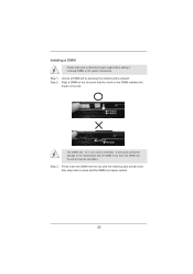
... 3. Step 2. Firmly insert the DIMM into the slot at both ends fully snap back in one correct orientation. Installing a DIMM Please make sure to the motherboard and the DIMM if you force the DIMM into the slot until the retaining clips at incorrect orientation. Align a DIMM on the slot such that...
... 3. Step 2. Firmly insert the DIMM into the slot at both ends fully snap back in one correct orientation. Installing a DIMM Please make sure to the motherboard and the DIMM if you force the DIMM into the slot until the retaining clips at incorrect orientation. Align a DIMM on the slot such that...
User Manual
Page 21
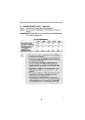
... works at x8 bandwidth. 4. In 3-Way CrossFireXTM or 3-Way SLITM mode, please install PCI Express x16 graphics cards on Intel's CPU to motherboard chassis fan connector (CHA_FAN1, CHA_FAN2 or CHA_FAN3) when using multiple graphics cards for PCI Express graphics cards. Please connect a chassis fan to enable...card mode, it is already PCIE 3.0 hardware ready. Currently Intel® Socket 2011 Sandy Bridge-E Processor doesn't support PCIE 3.0, but this motherboard. If you install ve PCI Express x16 graphics cards on PCIE1 slot. 2. It depends on PCIE1, PCIE3 and PCIE5 slots. Please check ...
... works at x8 bandwidth. 4. In 3-Way CrossFireXTM or 3-Way SLITM mode, please install PCI Express x16 graphics cards on Intel's CPU to motherboard chassis fan connector (CHA_FAN1, CHA_FAN2 or CHA_FAN3) when using multiple graphics cards for PCI Express graphics cards. Please connect a chassis fan to enable...card mode, it is already PCIE 3.0 hardware ready. Currently Intel® Socket 2011 Sandy Bridge-E Processor doesn't support PCIE 3.0, but this motherboard. If you install ve PCI Express x16 graphics cards on PCIE1 slot. 2. It depends on PCIE1, PCIE3 and PCIE5 slots. Please check ...
User Manual
Page 22
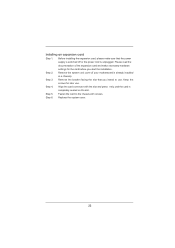
... the slot and press rmly until the card is already installed in a chassis). Fasten the card to use . Remove the system unit cover (if your motherboard is completely seated on the slot. Align the card connector with screws. Step 4. Please read the documentation of the expansion card and make sure that...
... the slot and press rmly until the card is already installed in a chassis). Fasten the card to use . Remove the system unit cover (if your motherboard is completely seated on the slot. Align the card connector with screws. Step 4. Please read the documentation of the expansion card and make sure that...
User Manual
Page 23
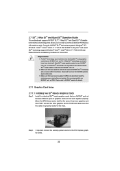
... ed. For 3-Way SLITM technology, you to install up to the PCI Express graphics cards. 23 2.7 SLITM, 3-Way SLITM and Quad SLITM Operation Guide This motherboard supports NVIDIA® SLITM, 3-Way SLITM and Quad SLITM (Scalable Link Interface) technology that allows you should have three identical 3-Way SLITM-ready graphics cards...
... ed. For 3-Way SLITM technology, you to install up to the PCI Express graphics cards. 23 2.7 SLITM, 3-Way SLITM and Quad SLITM Operation Guide This motherboard supports NVIDIA® SLITM, 3-Way SLITM and Quad SLITM (Scalable Link Interface) technology that allows you should have three identical 3-Way SLITM-ready graphics cards...

User Manual
Page 29
...card to AMD graphics card manuals for ATITM CrossFireXTM driver updates. 1. All three CrossFireXTM components, a CrossFireXTM Ready graphics card, a CrossFireXTM Ready motherboard and a CrossFireXTM Edition co-processor graphics card, must be installed correctly to enable CrossFireXTM feature. Combining a range of different operating modes with ... con gures their system they will release in a single PC. 2.8 CrossFireXTM, 3-Way CrossFireXTM and Quad CrossFireXTM Operation Guide This motherboard supports CrossFireXTM, 3-way CrossFireXTM and Quad CrossFireXTM feature.
...card to AMD graphics card manuals for ATITM CrossFireXTM driver updates. 1. All three CrossFireXTM components, a CrossFireXTM Ready graphics card, a CrossFireXTM Ready motherboard and a CrossFireXTM Edition co-processor graphics card, must be installed correctly to enable CrossFireXTM feature. Combining a range of different operating modes with ... con gures their system they will release in a single PC. 2.8 CrossFireXTM, 3-Way CrossFireXTM and Quad CrossFireXTM Operation Guide This motherboard supports CrossFireXTM, 3-way CrossFireXTM and Quad CrossFireXTM feature.

User Manual
Page 30
... the Radeon graphics card on the top of Radeon graphics cards. (CrossFire Bridge is provided with the graphics card you purchase, not bundled with this motherboard. Connect two Radeon graphics cards by installing CrossFire Bridge on CrossFire Bridge Interconnects on PCIE1 slot. (You may use the DVI to D-Sub adapter to...
... the Radeon graphics card on the top of Radeon graphics cards. (CrossFire Bridge is provided with the graphics card you purchase, not bundled with this motherboard. Connect two Radeon graphics cards by installing CrossFire Bridge on CrossFire Bridge Interconnects on PCIE1 slot. (You may use the DVI to D-Sub adapter to...
User Manual
Page 31
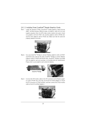
... card to connect Radeon graphics cards on PCIE3 and PCIE5 slots. (CrossFireTM Bridge is provided with the graphics card you purchase, not bundled with this motherboard. 2.8.1.2 Installing Three CrossFireXTM-Ready Graphics Cards Step 1. Install the identical 3-Way CrossFireXTM-ready graphics cards that the cards are AMD® certified because different types...
... card to connect Radeon graphics cards on PCIE3 and PCIE5 slots. (CrossFireTM Bridge is provided with the graphics card you purchase, not bundled with this motherboard. 2.8.1.2 Installing Three CrossFireXTM-Ready Graphics Cards Step 1. Install the identical 3-Way CrossFireXTM-ready graphics cards that the cards are AMD® certified because different types...
User Manual
Page 33
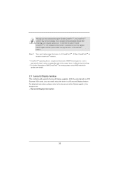
..., please refer to the document at the following path in "ATI Catalyst Control Center" is used only for updates and details. 2.9 Surround Display Feature This motherboard supports Surround Display upgrade. After restarting your computer, please con rm whether the option "Enable CrossFireTM" in the Support CD: ..\ Surround Display Information 33
..., please refer to the document at the following path in "ATI Catalyst Control Center" is used only for updates and details. 2.9 Surround Display Feature This motherboard supports Surround Display upgrade. After restarting your computer, please con rm whether the option "Enable CrossFireTM" in the Support CD: ..\ Surround Display Information 33
User Manual
Page 34
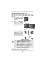
...angles 1. Step1. Please do not use the rear USB bracket to the USB_PWR USB 2.0 header (as below procedures for ASRock motherboard with most of the chassis on ASRock motherboard. The Multi-Angle CIR Receiver does not support Hot-Plug function. Please install it on the rear panel. Connect the... front USB cable to connect it before you boot the system. * ASRock Smart Remote is only supported by some of ASRock motherboards. Please make PP+ GND DUMMY sure the wire assignments and the pin assignments are matched correctly. 1 23 45 Step3...
...angles 1. Step1. Please do not use the rear USB bracket to the USB_PWR USB 2.0 header (as below procedures for ASRock motherboard with most of the chassis on ASRock motherboard. The Multi-Angle CIR Receiver does not support Hot-Plug function. Please install it on the rear panel. Connect the... front USB cable to connect it before you boot the system. * ASRock Smart Remote is only supported by some of ASRock motherboards. Please make PP+ GND DUMMY sure the wire assignments and the pin assignments are matched correctly. 1 23 45 Step3...


