User Manual
Page 13
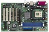
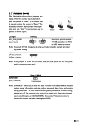
... the jumpers JL1 and JR1 are setup. Note: To select +5VSB, it requires 2 Amp and higher standby current provided by power supply. To clear and reset the system parameters to default setup, please turn off the computer and unplug the power cord, then use a jumper cap to remove the jumper cap...
... the jumpers JL1 and JR1 are setup. Note: To select +5VSB, it requires 2 Amp and higher standby current provided by power supply. To clear and reset the system parameters to default setup, please turn off the computer and unplug the power cord, then use a jumper cap to remove the jumper cap...

User Manual
Page 16
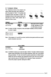
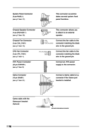
... installed. 1 +5V JAB2 JAY GND GND JAX JAB1 +5V connect to the connector. Chassis Fan Connector (3-pin CHA_FAN1) (see p.7 item 16) PLED+ PLEDPWRBTN# GND 1 DUMMY RESET# GND HDLEDHDLED+ 1 SPEAKER DUMMY DUMMY +5V This connector accommodates several system front panel functions.
... installed. 1 +5V JAB2 JAY GND GND JAX JAB1 +5V connect to the connector. Chassis Fan Connector (3-pin CHA_FAN1) (see p.7 item 16) PLED+ PLEDPWRBTN# GND 1 DUMMY RESET# GND HDLEDHDLED+ 1 SPEAKER DUMMY DUMMY +5V This connector accommodates several system front panel functions.
User Manual
Page 21
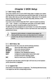
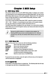
... Bar The top of the screen has a menu bar with their corresponding functions. 21 The Flash Memory on . You may also restart by pressing the reset button on your system.
... Bar The top of the screen has a menu bar with their corresponding functions. 21 The Flash Memory on . You may also restart by pressing the reset button on your system.
User Manual
Page 13
... system password, date, time, and system setup parameters. JR1(see p.7 item 27) JL1(see p.7 item 20) +5V +5VSB +5VSB (standby) for 3 seconds. To clear and reset the system parameters to default setup, please turn off the computer and unplug the power cord, then use a jumper cap to remove the jumper cap...
... system password, date, time, and system setup parameters. JR1(see p.7 item 27) JL1(see p.7 item 20) +5V +5VSB +5VSB (standby) for 3 seconds. To clear and reset the system parameters to default setup, please turn off the computer and unplug the power cord, then use a jumper cap to remove the jumper cap...
User Manual
Page 16
... wire to an external speaker. System Panel Connector (9-pin PANEL1) (see p.7 item 17) Chassis Speaker Connector (4-pin SPEAKER 1) (see p.7 item 16) PLED+ PLEDPWRBTN# GND 1 DUMMY RESET# GND HDLEDHDLED+ 1 SPEAKER DUMMY DUMMY +5V This connector accommodates several system front panel functions.
... wire to an external speaker. System Panel Connector (9-pin PANEL1) (see p.7 item 17) Chassis Speaker Connector (4-pin SPEAKER 1) (see p.7 item 16) PLED+ PLEDPWRBTN# GND 1 DUMMY RESET# GND HDLEDHDLED+ 1 SPEAKER DUMMY DUMMY +5V This connector accommodates several system front panel functions.
User Manual
Page 21
... ADVANCED Sets up the advanced features SECURITY Sets up the computer. It is designed to be user-friendly. You may also restart by pressing the reset button on . The BIOS Setup Utility is a menu-driven program, which allows you start up the security features POWER Configures Power Management features BOOT Configures...
... ADVANCED Sets up the advanced features SECURITY Sets up the computer. It is designed to be user-friendly. You may also restart by pressing the reset button on . The BIOS Setup Utility is a menu-driven program, which allows you start up the security features POWER Configures Power Management features BOOT Configures...


