User Manual
Page 3
Power Setup Menu 31 4. Advanced BIOS Setup Menu 26 2. Contents 1 Introduction 4 1.1 Package Contents 4 1.2 Specifications 5 1.3 Motherboard Layout 7 1.4 ASRock I/O PlusTM 8 2 Installation 9 2.1 Screw Holes 9 2.2 Pre-installation Precautions 9 2.3 CPU Installation 10 2.4 Installation of CPU Fan and ... Operating System 25 4.2 Support CD Information 25 4.2.1 Running Support CD 25 4.2.2 Drivers Menu 25 4.2.3 Utilities Menu 25 4.2.4 ASRock "PC-DIY Live Demo" Program 25 4.2.5 Contact Information 25 Appendix 26 1. Exit Menu 33 3 Security Setup Menu 30 3. Boot Setup Menu 32...
Power Setup Menu 31 4. Advanced BIOS Setup Menu 26 2. Contents 1 Introduction 4 1.1 Package Contents 4 1.2 Specifications 5 1.3 Motherboard Layout 7 1.4 ASRock I/O PlusTM 8 2 Installation 9 2.1 Screw Holes 9 2.2 Pre-installation Precautions 9 2.3 CPU Installation 10 2.4 Installation of CPU Fan and ... Operating System 25 4.2 Support CD Information 25 4.2.1 Running Support CD 25 4.2.2 Drivers Menu 25 4.2.3 Utilities Menu 25 4.2.4 ASRock "PC-DIY Live Demo" Program 25 4.2.5 Contact Information 25 Appendix 26 1. Exit Menu 33 3 Security Setup Menu 30 3. Boot Setup Menu 32...
User Manual
Page 4
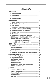
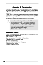
... setup and support CD information. ASRock website http://www.asrock.com 1.1 Package Contents ASRock P4VT8+ Motherboard (ATX Form Factor: 12.0-in x 7.5-in, 30.5 cm x 19.1 cm) ASRock P4VT8+ Quick Installation Guide ASRock P4VT8+ Support CD One 80-conductor Ultra ATA 66/100/133 IDE Ribbon Cable One Ribbon Cable for purchasing ASRock P4VT8+ motherboard, a reliable motherboard produced under ASRock's consistently stringent quality control. Chapter...
... setup and support CD information. ASRock website http://www.asrock.com 1.1 Package Contents ASRock P4VT8+ Motherboard (ATX Form Factor: 12.0-in x 7.5-in, 30.5 cm x 19.1 cm) ASRock P4VT8+ Quick Installation Guide ASRock P4VT8+ Support CD One 80-conductor Ultra ATA 66/100/133 IDE Ribbon Cable One Ribbon Cable for purchasing ASRock P4VT8+ motherboard, a reliable motherboard produced under ASRock's consistently stringent quality control. Chapter...
User Manual
Page 6
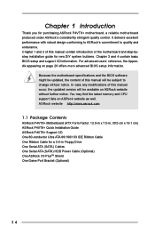
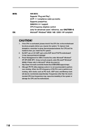
...the heatsink when you resume the system. Do NOT use a 3.3V AGP card on the AGP slot of P4VT8+ is overheated, please check if the CPU fan on the motherboard functions properly before you install the PC system. 2. It may cause permanent damage! 3. Frequencies other clocks,... Memory clock will also be overclocked proportionally. ACPI 1.1 compliance wake up events; Please refer to perform over clocking. When the CPU frequency of P4VT8+ motherboard! Supports "Plug and Play"; BIOS: OS: AMI BIOS; SMBIOS 2.3.1 support; If the CPU is set to Microsoft® official document at...
...the heatsink when you resume the system. Do NOT use a 3.3V AGP card on the AGP slot of P4VT8+ is overheated, please check if the CPU fan on the motherboard functions properly before you install the PC system. 2. It may cause permanent damage! 3. Frequencies other clocks,... Memory clock will also be overclocked proportionally. ACPI 1.1 compliance wake up events; Please refer to perform over clocking. When the CPU frequency of P4VT8+ motherboard! Supports "Plug and Play"; BIOS: OS: AMI BIOS; SMBIOS 2.3.1 support; If the CPU is set to Microsoft® official document at...
User Manual
Page 9
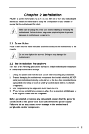
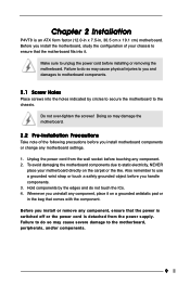
... pad or in , 30.5 cm x 19.1 cm) motherboard. Do not over-tighten the screws! Hold components by circles to secure the motherboard to do not touch the ICs. 4. Failure to the chassis. Chapter 2 Installation P4VT8+ is detached from the wall socket before touching any component.... 2. Before you and damages to static electricity, NEVER place your chassis to the motherboard, peripherals, and/or components. 9 Unplug the power cord from...
... pad or in , 30.5 cm x 19.1 cm) motherboard. Do not over-tighten the screws! Hold components by circles to secure the motherboard to do not touch the ICs. 4. Failure to the chassis. Chapter 2 Installation P4VT8+ is detached from the wall socket before touching any component.... 2. Before you and damages to static electricity, NEVER place your chassis to the motherboard, peripherals, and/or components. 9 Unplug the power cord from...
User Manual
Page 11
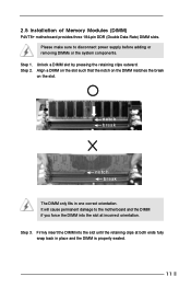
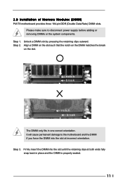
... seated. 11 It will cause permanent damage to disconnect power supply before adding or removing DIMMs or the system components. Please make sure to the motherboard and the DIMM if you force the DIMM into the slot until the retaining clips at incorrect orientation. 2.5 Installation of Memory Modules (DIMM...
... seated. 11 It will cause permanent damage to disconnect power supply before adding or removing DIMMs or the system components. Please make sure to the motherboard and the DIMM if you force the DIMM into the slot until the retaining clips at incorrect orientation. 2.5 Installation of Memory Modules (DIMM...
User Manual
Page 12
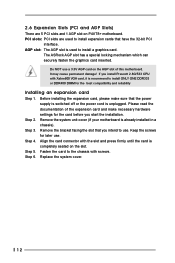
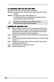
.... Keep the screws for the card before you intend to use. Align the card connector with Xabre600 VGA card, it is completely seated on P4VT8+ motherboard. 2.6 Expansion Slots (PCI and AGP Slots) There are used to the chassis with screws. PCI slots: PCI slots are 5 PCI slots ...is switched off or the power cord is already installed in a chassis). Step 4. Replace the system cover. 12 Step 5. Step 6. The ASRock AGP slot has a special locking mechanism which can securely fasten the graphics card inserted. It may cause permanent damage! Remove the system unit cover ...
.... Keep the screws for the card before you intend to use. Align the card connector with Xabre600 VGA card, it is completely seated on P4VT8+ motherboard. 2.6 Expansion Slots (PCI and AGP Slots) There are used to the chassis with screws. PCI slots: PCI slots are 5 PCI slots ...is switched off or the power cord is already installed in a chassis). Step 4. Replace the system cover. 12 Step 5. Step 6. The ASRock AGP slot has a special locking mechanism which can securely fasten the graphics card inserted. It may cause permanent damage! Remove the system unit cover ...
User Manual
Page 14
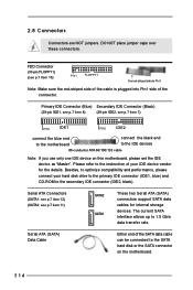
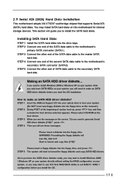
... IDE Connector (Black) (39-pin IDE1, see p.7 item 8) (39-pin IDE2, see p.7 item 7) PIN1 IDE1 PIN1 IDE2 connect the blue end to the motherboard connect the black end to 1.5 Gb/s data transfer rate. Serial ATA (SATA) Data Cable Either end of the connector. Serial ATA Connectors (SATA1: see p.7 item... your hard disk drive to the primary IDE connector (IDE1, blue) and CD-ROM to the SATA hard disk or the SATA connector on this motherboard, please set the IDE device as "Master". DO NOT place jumper caps over these connectors. FDD Connector (33-pin FLOPPY1) (see p.7 item ...
... IDE Connector (Black) (39-pin IDE1, see p.7 item 8) (39-pin IDE2, see p.7 item 7) PIN1 IDE1 PIN1 IDE2 connect the blue end to the motherboard connect the black end to 1.5 Gb/s data transfer rate. Serial ATA (SATA) Data Cable Either end of the connector. Serial ATA Connectors (SATA1: see p.7 item... your hard disk drive to the primary IDE connector (IDE1, blue) and CD-ROM to the SATA hard disk or the SATA connector on this motherboard, please set the IDE device as "Master". DO NOT place jumper caps over these connectors. FDD Connector (33-pin FLOPPY1) (see p.7 item ...
User Manual
Page 17
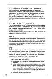
... a diskette into your optical drive to boot your system, or you may install SATA hard disks on your system, you will guide you to the motherboard's secondary SATA connector (SATA2). Installing SATA Hard Disks STEP 1: Install the SATA hard disks into the floppy drive, and press . STEP 5: Connect...ALL data in it! How to make an SATA HDD driver diskette before you start to the secondary SATA hard disk. STEP 1: Insert the ASRock Support CD into the floppy drive WARNING! Formatting the floppy diskette will start the OS installation. STEP 3: Connect the other end of the ...
... a diskette into your optical drive to boot your system, or you may install SATA hard disks on your system, you will guide you to the motherboard's secondary SATA connector (SATA2). Installing SATA Hard Disks STEP 1: Install the SATA hard disks into the floppy drive, and press . STEP 5: Connect...ALL data in it! How to make an SATA HDD driver diskette before you start to the secondary SATA hard disk. STEP 1: Insert the ASRock Support CD into the floppy drive WARNING! Formatting the floppy diskette will start the OS installation. STEP 3: Connect the other end of the ...
User Manual
Page 18
... the floppy diskette, and reboot the system. At the very beginning, you are creating a RAID 1 (mirroring) array for the proper installation. 2.9.2 RAID 0 / RAID 1 Configurations This motherboard adopts VIA VT8237 southbridge chipset that integrates RAID controller supporting RAID 0 and RAID 1 with two independent Serial ATA (SATA) channels.
... the floppy diskette, and reboot the system. At the very beginning, you are creating a RAID 1 (mirroring) array for the proper installation. 2.9.2 RAID 0 / RAID 1 Configurations This motherboard adopts VIA VT8237 southbridge chipset that integrates RAID controller supporting RAID 0 and RAID 1 with two independent Serial ATA (SATA) channels.
User Manual
Page 21
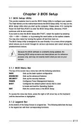
... System EXIT Exits the current menu or the BIOS Setup To access the menu bar items, press the right or left arrow key on the motherboard stores the BIOS Setup Utility.
... System EXIT Exits the current menu or the BIOS Setup To access the menu bar items, press the right or left arrow key on the motherboard stores the BIOS Setup Utility.
User Manual
Page 25
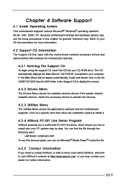
...more information. 4.2 Support CD Information The Support CD that came with the motherboard contains necessary drivers and useful utilities that the motherboard supports. Chapter 4 Software Support 4.1 Install Operating System This motherboard supports various Microsoft® Windows® operating systems: 98 SE / ME ... program, you may contact your OS documentation for more about ASRock, welcome to activate the devices. 4.2.3 Utilities Menu The Utilities Menu shows the applications software that enhance the motherboard features. 4.2.1 Running The Support CD To begin using the support...
...more information. 4.2 Support CD Information The Support CD that came with the motherboard contains necessary drivers and useful utilities that the motherboard supports. Chapter 4 Software Support 4.1 Install Operating System This motherboard supports various Microsoft® Windows® operating systems: 98 SE / ME ... program, you may contact your OS documentation for more about ASRock, welcome to activate the devices. 4.2.3 Utilities Menu The Utilities Menu shows the applications software that enhance the motherboard features. 4.2.1 Running The Support CD To begin using the support...
User Manual
Page 26
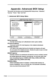
...Frequency Flexibility Option Disabled Disabled 133MHz Locked Auto Disabled [ Setup Help ] to enable or disable the feature of the installed motherboard. DRAM Frequency: If [Auto] is the multiple that times the frontside bus frequency will allow better tolerance for better ...system stability. CPU Ratio Selection: CPU Ratio is selected, the motherboard will automatic to [Disabled] for memory compatibility. Flexibility Option: Default is determined by the installed processor. Chipset Configuration Resource ...
...Frequency Flexibility Option Disabled Disabled 133MHz Locked Auto Disabled [ Setup Help ] to enable or disable the feature of the installed motherboard. DRAM Frequency: If [Auto] is the multiple that times the frontside bus frequency will allow better tolerance for better ...system stability. CPU Ratio Selection: CPU Ratio is selected, the motherboard will automatic to [Disabled] for memory compatibility. Flexibility Option: Default is determined by the installed processor. Chipset Configuration Resource ...
User Manual
Page 27
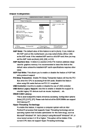
... support to select AGP mode. Set to enable or disable the feature of USB controller. Chipset Configuration: Advanced AMIBIOS SETUP UTILITY - USB Controller: Use this motherboard, you install an 8X-AGP card on this to [Auto]. VERSION 3.31a Chipset Configuration [ Setup Help ] AGP Mode AGP Aperture Size AGP Fast Write PCI...
... support to select AGP mode. Set to enable or disable the feature of USB controller. Chipset Configuration: Advanced AMIBIOS SETUP UTILITY - USB Controller: Use this motherboard, you install an 8X-AGP card on this to [Auto]. VERSION 3.31a Chipset Configuration [ Setup Help ] AGP Mode AGP Aperture Size AGP Fast Write PCI...

User Manual
Page 29
The default value is set addresses for the onboard AC'97 Audio feature. OnBoard Game Port: Select address for CPU temperature, Motherboard temperature, CPU fan speed, and critical voltage. OnBoard Parallel Port: Select Parallel Port address or disable Parallel Port. If this option is [ECP+CPP]. It ...
The default value is set addresses for the onboard AC'97 Audio feature. OnBoard Game Port: Select address for CPU temperature, Motherboard temperature, CPU fan speed, and critical voltage. OnBoard Parallel Port: Select Parallel Port address or disable Parallel Port. If this option is [ECP+CPP]. It ...
User Manual
Page 3
Boot Setup Menu 32 5. Exit Menu 33 3 Contents 1 Introduction 4 1.1 Package Contents 4 1.2 Specifications 5 1.3 Motherboard Layout 7 1.4 ASRock I/O PlusTM 8 2 Installation 9 2.1 Screw Holes 9 2.2 Pre-installation Precautions 9 2.3 CPU Installation 10 2.4 Installation of CPU Fan and ...25 4.1 Install Operating System 25 4.2 Support CD Information 25 4.2.1 Running Support CD 25 4.2.2 Drivers Menu 25 4.2.3 Utilities Menu 25 4.2.4 ASRock "PC-DIY Live Demo" Program 25 4.2.5 Contact Information 25 Appendix 26 1. Advanced BIOS Setup Menu 26 2. Security Setup Menu 30 3. Power ...
Boot Setup Menu 32 5. Exit Menu 33 3 Contents 1 Introduction 4 1.1 Package Contents 4 1.2 Specifications 5 1.3 Motherboard Layout 7 1.4 ASRock I/O PlusTM 8 2 Installation 9 2.1 Screw Holes 9 2.2 Pre-installation Precautions 9 2.3 CPU Installation 10 2.4 Installation of CPU Fan and ...25 4.1 Install Operating System 25 4.2 Support CD Information 25 4.2.1 Running Support CD 25 4.2.2 Drivers Menu 25 4.2.3 Utilities Menu 25 4.2.4 ASRock "PC-DIY Live Demo" Program 25 4.2.5 Contact Information 25 Appendix 26 1. Advanced BIOS Setup Menu 26 2. Security Setup Menu 30 3. Power ...
User Manual
Page 4
... for new DIY system builders. ASRock website http://www.asrock.com 1.1 Package Contents ASRock P4VT8 Motherboard (ATX Form Factor: 12.0-in x 7.5-in, 30.5 cm x 19.1 cm) ASRock P4VT8 Quick Installation Guide ASRock P4VT8 Support CD One 80-conductor Ultra ATA 66/100/133 IDE Ribbon Cable One Ribbon Cable for purchasing ASRock P4VT8 motherboard, a reliable motherboard produced under ASRock's consistently stringent quality control. Chapter...
... for new DIY system builders. ASRock website http://www.asrock.com 1.1 Package Contents ASRock P4VT8 Motherboard (ATX Form Factor: 12.0-in x 7.5-in, 30.5 cm x 19.1 cm) ASRock P4VT8 Quick Installation Guide ASRock P4VT8 Support CD One 80-conductor Ultra ATA 66/100/133 IDE Ribbon Cable One Ribbon Cable for purchasing ASRock P4VT8 motherboard, a reliable motherboard produced under ASRock's consistently stringent quality control. Chapter...
User Manual
Page 6
...XP SP1/2000 SP4. Although P4VT8 offers stepless control, it is set to perform over clocking, other than the recom mended CPU bus frequencies may cause the instability of the system or damage the CPU and the motherboard. 6 When the CPU frequency of P4VT8 motherboard! Do NOT use a 3....3V AGP card on the motherboard functions properly before you install the PC system. 2. Power Management for advanced users' reference, see...
...XP SP1/2000 SP4. Although P4VT8 offers stepless control, it is set to perform over clocking, other than the recom mended CPU bus frequencies may cause the instability of the system or damage the CPU and the motherboard. 6 When the CPU frequency of P4VT8 motherboard! Do NOT use a 3....3V AGP card on the motherboard functions properly before you install the PC system. 2. Power Management for advanced users' reference, see...
User Manual
Page 9
... Hold components by circles to secure the motherboard to ensure that comes with the component. Before you install or remove any component, place it on the carpet or the like. Do not over-tighten the screws! Chapter 2 Installation P4VT8 is detached from the wall socket before you... install motherboard components or change any component. 2. Make sure to use a grounded wrist strap or touch a safety grounded object ...
... Hold components by circles to secure the motherboard to ensure that comes with the component. Before you install or remove any component, place it on the carpet or the like. Do not over-tighten the screws! Chapter 2 Installation P4VT8 is detached from the wall socket before you... install motherboard components or change any component. 2. Make sure to use a grounded wrist strap or touch a safety grounded object ...
User Manual
Page 11
It will cause permanent damage to disconnect power supply before adding or removing DIMMs or the system components. 2.5 Installation of Memory Modules (DIMM) P4VT8 motherboard provides three 184-pin DDR (Double Data Rate) DIMM slots. Unlock a DIMM slot by pressing the retaining clips outward. Step 3. Step 1.... orientation. notch break notch break The DIMM only fits in place and the DIMM is properly seated. 11 Please make sure to the motherboard and the DIMM if you force the DIMM into the slot until the retaining clips at incorrect orientation. Step 2. Align a DIMM on...
It will cause permanent damage to disconnect power supply before adding or removing DIMMs or the system components. 2.5 Installation of Memory Modules (DIMM) P4VT8 motherboard provides three 184-pin DDR (Double Data Rate) DIMM slots. Unlock a DIMM slot by pressing the retaining clips outward. Step 3. Step 1.... orientation. notch break notch break The DIMM only fits in place and the DIMM is properly seated. 11 Please make sure to the motherboard and the DIMM if you force the DIMM into the slot until the retaining clips at incorrect orientation. Step 2. Align a DIMM on...
User Manual
Page 12
... the power supply is switched off or the power cord is completely seated on P4VT8 motherboard. Fasten the card to install a graphics card. It may cause permanent damage! Please read the documentation of P4VT8 motherboard! Keep the screws for the card before you intend to use. AGP slot:... are 5 PCI slots and 1 AGP slot on the slot. Remove the system unit cover (if your motherboard is used to install expansion cards that you start the installation. The ASRock AGP slot has a special locking mechanism which can securely fasten the graphics card inserted. Do NOT use ...
... the power supply is switched off or the power cord is completely seated on P4VT8 motherboard. Fasten the card to install a graphics card. It may cause permanent damage! Please read the documentation of P4VT8 motherboard! Keep the screws for the card before you intend to use. AGP slot:... are 5 PCI slots and 1 AGP slot on the slot. Remove the system unit cover (if your motherboard is used to install expansion cards that you start the installation. The ASRock AGP slot has a special locking mechanism which can securely fasten the graphics card inserted. Do NOT use ...

