User Manual
Page 6
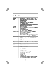
.../2 Keyboard Port - 1 x Serial Port: COM1 - 1 x Parallel Port (ECP/EPP Support) - 4 x Ready-to 12.5% (see CAUTION 5) - Support DDRII800/667/533 - Supports AMD's Cool 'n' QuietTM Technology - ASRock U-COP (see CAUTION 6) - 1 x PCI Express x16 slot (White) - 2 x PCI Express x8 slots (Yellow; ASRock AM2 Boost: ASRock Patented Technology to boost memory performance up to -Use USB 2.0 Ports - 1 x eSATAII Port - 1 x RJ-45 Port - 1 x IEEE 1394 Port -
.../2 Keyboard Port - 1 x Serial Port: COM1 - 1 x Parallel Port (ECP/EPP Support) - 4 x Ready-to 12.5% (see CAUTION 5) - Support DDRII800/667/533 - Supports AMD's Cool 'n' QuietTM Technology - ASRock U-COP (see CAUTION 6) - 1 x PCI Express x16 slot (White) - 2 x PCI Express x8 slots (Yellow; ASRock AM2 Boost: ASRock Patented Technology to boost memory performance up to -Use USB 2.0 Ports - 1 x eSATAII Port - 1 x RJ-45 Port - 1 x IEEE 1394 Port -

User Manual
Page 7
AMI Legal BIOS - SMBIOS 2.3.1 Support - CPU Ambient Temperature Sensing - CPU Fan Tachometer - Front panel audio connector - 2 x USB 2.0 headers (support 4 USB 2.0 ports) (see CAUTION 12) - Voltage Monitoring: +12V, +5V, +3.3V, Vcore - CD in header - Microsoft® Windows® 2000 / XP / XP Media Center ... functions (see CAUTION 10) - 2 x ATA133 IDE connectors (support 4 x IDE devices) - 1 x Floppy connector - 1 x IR header - 1 x Game header - 1 x HDMI_SPDIF header - 1 x IEEE 1394 header - Supports "Plug and Play" - CPU Internal Temperature Sensing - CPU Quiet Fan -
AMI Legal BIOS - SMBIOS 2.3.1 Support - CPU Ambient Temperature Sensing - CPU Fan Tachometer - Front panel audio connector - 2 x USB 2.0 headers (support 4 USB 2.0 ports) (see CAUTION 12) - Voltage Monitoring: +12V, +5V, +3.3V, Vcore - CD in header - Microsoft® Windows® 2000 / XP / XP Media Center ... functions (see CAUTION 10) - 2 x ATA133 IDE connectors (support 4 x IDE devices) - 1 x Floppy connector - 1 x IR header - 1 x Game header - 1 x HDMI_SPDIF header - 1 x IEEE 1394 header - Supports "Plug and Play" - CPU Internal Temperature Sensing - CPU Quiet Fan -

User Manual
Page 12
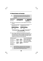
... below for Audio Output Connection Audio Output Channels Front Speaker Rear Speaker (No. 9) (No. 6) Central / Bass Side Speaker (No. 7) (No. 5) 2 V -- -- -- 4 V -- -- V 6 V -- 1.6 ASRock 1394_eSATAII I/O Plus 1 PS/2 Mouse Port (Green) 2 Parallel Port 3 IEEE 1394 Port 4 RJ-45 Port 5 Side Speaker (Gray) 6 Rear Speaker (Black) 7 Central / Bass (Orange) 8 Line In (Light Blue) * 9 Front Speaker (Lime) 10 Microphone (Pink) 11 USB...
... below for Audio Output Connection Audio Output Channels Front Speaker Rear Speaker (No. 9) (No. 6) Central / Bass Side Speaker (No. 7) (No. 5) 2 V -- -- -- 4 V -- -- V 6 V -- 1.6 ASRock 1394_eSATAII I/O Plus 1 PS/2 Mouse Port (Green) 2 Parallel Port 3 IEEE 1394 Port 4 RJ-45 Port 5 Side Speaker (Gray) 6 Rear Speaker (Black) 7 Central / Bass (Orange) 8 Line In (Light Blue) * 9 Front Speaker (Lime) 10 Microphone (Pink) 11 USB...
User Manual
Page 23
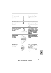
...caps over these headers and connectors. Serial ATAII Connectors (SATAII_BLACK (PORT 1.0): see p.11, No. 12) SATAII_BLUE (SATAII_ORANGE (PORT 1.1): (PORT 2.0) see p.11, No. 13) (SATAII_BLUE (PORT 2.0): see p.11, No. 15) (SATAII_RED (PORT 2.1): see p.11 No. 10) PIN1 IDE1 PIN1 IDE2 connect ... see p.11 No. 11) Secondary IDE Connector (Black) (39-pin IDE2, see p.11, No. 14) SATAII_RED (PORT 2.1) SATAII_BLACK (PORT 1.0) SATAII_ORANGE (PORT 1.1) These four Serial ATAII (SATAII) connectors support SATA data cables for details about eSATAII and eSATAII installation procedures. 23 2.7...
...caps over these headers and connectors. Serial ATAII Connectors (SATAII_BLACK (PORT 1.0): see p.11, No. 12) SATAII_BLUE (SATAII_ORANGE (PORT 1.1): (PORT 2.0) see p.11, No. 13) (SATAII_BLUE (PORT 2.0): see p.11, No. 15) (SATAII_RED (PORT 2.1): see p.11 No. 10) PIN1 IDE1 PIN1 IDE2 connect ... see p.11 No. 11) Secondary IDE Connector (Black) (39-pin IDE2, see p.11, No. 14) SATAII_RED (PORT 2.1) SATAII_BLACK (PORT 1.0) SATAII_ORANGE (PORT 1.1) These four Serial ATAII (SATAII) connectors support SATA data cables for details about eSATAII and eSATAII installation procedures. 23 2.7...

User Manual
Page 24
... and receiving infrared module. 24 Then connect the white end of the SATA data cable can also use the SATA data cable to connect SATAII_RED (PORT 2.1) connector and eSATAII connector. USB 2.0 Headers (9-pin USB6_7) (see p.11 No. 18) (9-pin USB4_5) (see p.11 No. 19) USB_PWR P-7 P+7 GND ...DUMMY 1 GND P+6 P-6 USB_PWR USB_PWR P-5 P+5 GND DUMMY 1 GND P+4 P-4 USB_PWR Besides four default USB 2.0 ports on the I/O panel, there are two USB 2.0 headers on this motherboard. The current eSATAII interface allows up to the SATA / SATAII hard disk or the...
... and receiving infrared module. 24 Then connect the white end of the SATA data cable can also use the SATA data cable to connect SATAII_RED (PORT 2.1) connector and eSATAII connector. USB 2.0 Headers (9-pin USB6_7) (see p.11 No. 18) (9-pin USB4_5) (see p.11 No. 19) USB_PWR P-7 P+7 GND ...DUMMY 1 GND P+6 P-6 USB_PWR USB_PWR P-5 P+5 GND DUMMY 1 GND P+4 P-4 USB_PWR Besides four default USB 2.0 ports on the I/O panel, there are two USB 2.0 headers on this motherboard. The current eSATAII interface allows up to the SATA / SATAII hard disk or the...

User Manual
Page 26
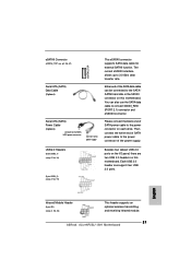
Game Port Header (15-pin GAME1) (see p.11 No. 26) IEEE 1394 Header (9-pin FRONT_1394) (see p.11, No. 2) Please connect an ATX power supply ...11 No. 3) SLI/XFIRE_POWER1 It is not necessary to use this connector, but please connect it is one IEEE 1394 header (FRONT_1394) on the I/O panel, there is necessary to connect a power supply with a hard disk power... connecor when two graphics cards are plugged to this motherboard. Failing to this connector. Besides one IEEE 1394 port. 26 SLI/XFIRE Power Connector (4-pin SLI/XFIRE_POWER1) (see p.11, No. 7) Please note that it with...
Game Port Header (15-pin GAME1) (see p.11 No. 26) IEEE 1394 Header (9-pin FRONT_1394) (see p.11, No. 2) Please connect an ATX power supply ...11 No. 3) SLI/XFIRE_POWER1 It is not necessary to use this connector, but please connect it is one IEEE 1394 header (FRONT_1394) on the I/O panel, there is necessary to connect a power supply with a hard disk power... connecor when two graphics cards are plugged to this motherboard. Failing to this connector. Besides one IEEE 1394 port. 26 SLI/XFIRE Power Connector (4-pin SLI/XFIRE_POWER1) (see p.11, No. 7) Please note that it with...

User Manual
Page 29
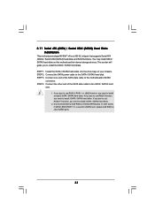
... the eSATAII HDD as a RAID disk, please set "SATA Operation Mode" option in the near future, eSATAII will replace USB 2.0 and IEEE 1394 to exchange your computer, offering the high speed data transfer rate up to 3.0Gb/s, and the convenient mobility like USB. However, eSATAII provides the... data transfer rate up to 3000Mb/s, which is not supported with eSATAII devices. If you to the eSATAII ports only when the system is power-on the basis of your SATAII hard disk. 2.9 eSATAII Interface Introduction What is supported with eSATAII devices. ...
... the eSATAII HDD as a RAID disk, please set "SATA Operation Mode" option in the near future, eSATAII will replace USB 2.0 and IEEE 1394 to exchange your computer, offering the high speed data transfer rate up to 3.0Gb/s, and the convenient mobility like USB. However, eSATAII provides the... data transfer rate up to 3000Mb/s, which is not supported with eSATAII devices. If you to the eSATAII ports only when the system is power-on the basis of your SATAII hard disk. 2.9 eSATAII Interface Introduction What is supported with eSATAII devices. ...

User Manual
Page 30
...eSATAII connector (eSATAII_TOP) 2. Connect one end of the eSATAII device cable to eSATAII device Connect the other end of the eSATAII device cable to eSATAII port of the I/O shield. see p.11 No.37) with a SATA data cable first. Connect the SATA data cable to the red SATAII connector (SATAII_RED... (PORT 2.1)) Connect the SATA data cable to install eSATAII? see p.11 No.14) and the eSATAII connector (eSATAII_TOP; Use the eSATAII device cable to connect ...
...eSATAII connector (eSATAII_TOP) 2. Connect one end of the eSATAII device cable to eSATAII device Connect the other end of the eSATAII device cable to eSATAII port of the I/O shield. see p.11 No.37) with a SATA data cable first. Connect the SATA data cable to the red SATAII connector (SATAII_RED... (PORT 2.1)) Connect the SATA data cable to install eSATAII? see p.11 No.14) and the eSATAII connector (eSATAII_TOP; Use the eSATAII device cable to connect ...
User Manual
Page 33
... / SATAII hard disk. 1. STEP 2: Connect the SATA power cable to install 4 SATA / SATAII hard disks. 2. It is used for eSATAII port, please build RAID on other end of the SATA data cable to build RAID on this motherboard for internal storage devices. If you plan to ...If you plan to use RAID 5 function, you need to the SATA / SATAII hard disk. You may install SATA / SATAII hard disks on internal SATAII ports. 2.11 Serial ATA (SATA) / Serial ATAII (SATAII) Hard Disks Installation This motherboard adopts NVIDIA® nForce 560 SLI chipset that supports Serial ATA (SATA...
... / SATAII hard disk. 1. STEP 2: Connect the SATA power cable to install 4 SATA / SATAII hard disks. 2. It is used for eSATAII port, please build RAID on other end of the SATA data cable to build RAID on this motherboard for internal storage devices. If you plan to ...If you plan to use RAID 5 function, you need to the SATA / SATAII hard disk. You may install SATA / SATAII hard disks on internal SATAII ports. 2.11 Serial ATA (SATA) / Serial ATAII (SATAII) Hard Disks Installation This motherboard adopts NVIDIA® nForce 560 SLI chipset that supports Serial ATA (SATA...
User Manual
Page 34
... under Windows® VistaTM and VistaTM 64-bit OS. 34 However, please note that enables you may simply plug your eSATAII devices to the eSATAII ports instead of opening your chassis to exchange drives easily. 2.12 Hot Plug and Hot Swap Functions for SATA / SATAII HDDs and eSATAII Devices This motherboard...
... under Windows® VistaTM and VistaTM 64-bit OS. 34 However, please note that enables you may simply plug your eSATAII devices to the eSATAII ports instead of opening your chassis to exchange drives easily. 2.12 Hot Plug and Hot Swap Functions for SATA / SATAII HDDs and eSATAII Devices This motherboard...
User Manual
Page 48
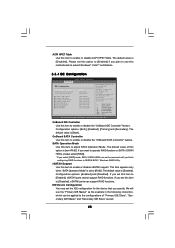
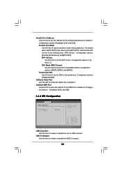
... which can support RAID functions. This item appears only when "SATA Operation Mode" is [Disabled]. If you plan to [Enabled], eSATAII ports cannot support RAID functions. Secondary: enables only the Secondary IDE Controller. Configuration options: [Both], [Disabled], [Primary] and [Secondary]. Please...the "OnBoard SATA Controller" feature. Configuration options: [Enabled] and [Disabled]. We will use this motherboard to [Disabled], eSATAII ports can be accessed until you set the IDE configuration for the device that you specify. OnBoard SATA Controller Use this item to...
... which can support RAID functions. This item appears only when "SATA Operation Mode" is [Disabled]. If you plan to [Enabled], eSATAII ports cannot support RAID functions. Secondary: enables only the Secondary IDE Controller. Configuration options: [Both], [Disabled], [Primary] and [Secondary]. Please...the "OnBoard SATA Controller" feature. Configuration options: [Enabled] and [Disabled]. We will use this motherboard to [Disabled], eSATAII ports can be accessed until you set the IDE configuration for the device that you specify. OnBoard SATA Controller Use this item to...
User Manual
Page 51
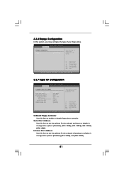
... Change Option General Help Load Defaults Save and Exit Exit v02.54 (C) Copyright 1985-2003, American Megatrends, Inc. Serial Port Address Use this section, you may configure the type of floppy drive connected to the system. +F1 F9 F10 ESC ...Inc. 3.3.7 Super IO Configuration BIOS SETUP UTILITY Advanced Configure Super IO Chipset OnBoard Floppy Controller Serial Port Address Infrared Port Address Parallel Port Address Parallel Port Mode EPP Version ECP Mode DMA Channel Parallel Port IRQ OnBoard Game Port OnBoard MIDI Port [Enabled] [3F8 / IRQ4] [Disabled] [378] [ECP + EPP] [1.9] [DMA3] ...
... Change Option General Help Load Defaults Save and Exit Exit v02.54 (C) Copyright 1985-2003, American Megatrends, Inc. Serial Port Address Use this section, you may configure the type of floppy drive connected to the system. +F1 F9 F10 ESC ...Inc. 3.3.7 Super IO Configuration BIOS SETUP UTILITY Advanced Configure Super IO Chipset OnBoard Floppy Controller Serial Port Address Infrared Port Address Parallel Port Address Parallel Port Mode EPP Version ECP Mode DMA Channel Parallel Port IRQ OnBoard Game Port OnBoard MIDI Port [Enabled] [3F8 / IRQ4] [Disabled] [378] [ECP + EPP] [1.9] [DMA3] ...
User Manual
Page 52
...enable or disable the USB 2.0 support. 52 USB 2.0 Support Use this item to enable the Game Port or disable it will show the EPP version in the following item, "EPP Version". Configuration options:... to enable or disable the use of the parallel port. Configuration options: [1.9] and [1.7]. OnBoard MIDI Port Use this item to set the IRQ for the MIDI Port or disable it . ECP Mode DMA Channel Use ...this item to set the operation mode of USB controller. Parallel Port Mode Use this item to set the ECP mode DMA channel. Configuration options: [Normal], [Bi-...
...enable or disable the USB 2.0 support. 52 USB 2.0 Support Use this item to enable the Game Port or disable it will show the EPP version in the following item, "EPP Version". Configuration options:... to enable or disable the use of the parallel port. Configuration options: [1.9] and [1.7]. OnBoard MIDI Port Use this item to set the IRQ for the MIDI Port or disable it . ECP Mode DMA Channel Use ...this item to set the operation mode of USB controller. Parallel Port Mode Use this item to set the ECP mode DMA channel. Configuration options: [Normal], [Bi-...
Quick Installation Guide
Page 2
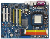
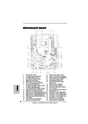
...(PANEL1) 5 AM2 940-Pin CPU Socket 23 Infrared Module Header (IR1) 6 NVIDIA nForce 560 SLI Chipset 24 Front Panel IEEE 1394 Header 7 ATX 12V Power Connector (ATX12V1) (FRONT_1394) 8 2 x 240-pin DDRII DIMM Slots 25 Floppy Connector (FLOPPY1) (Dual...PORT 2.1)) 33 PCI Express x16 Slot (PCIE3, White) 15 SATAII Connector (SATAII_BLUE (PORT 2.0)) 34 PCI Express x8 Slot (PCIE2, Yellow) 16 Flash Memory 35 PCI Express x1 Slot (PCIE1) 17 Clear CMOS Jumper (CLRCMOS1) 36 CPU Fan Connector (CPU_FAN1) 18 USB 2.0 Header (USB6_7, Blue) 37 eSATAII Connector (eSATAII_TOP) 2 ASRock ALiveNF5SLI-1394...
...(PANEL1) 5 AM2 940-Pin CPU Socket 23 Infrared Module Header (IR1) 6 NVIDIA nForce 560 SLI Chipset 24 Front Panel IEEE 1394 Header 7 ATX 12V Power Connector (ATX12V1) (FRONT_1394) 8 2 x 240-pin DDRII DIMM Slots 25 Floppy Connector (FLOPPY1) (Dual...PORT 2.1)) 33 PCI Express x16 Slot (PCIE3, White) 15 SATAII Connector (SATAII_BLUE (PORT 2.0)) 34 PCI Express x8 Slot (PCIE2, Yellow) 16 Flash Memory 35 PCI Express x1 Slot (PCIE1) 17 Clear CMOS Jumper (CLRCMOS1) 36 CPU Fan Connector (CPU_FAN1) 18 USB 2.0 Header (USB6_7, Blue) 37 eSATAII Connector (eSATAII_TOP) 2 ASRock ALiveNF5SLI-1394...

Quick Installation Guide
Page 3
...ASRock 1394_eSATAII I/O Plus 1 PS/2 Mouse Port (Green) 2 Parallel Port 3 IEEE 1394 Port 4 RJ-45 Port 5 Side Speaker (Gray) 6 Rear Speaker (Black) 7 Central / Bass (Orange) 8 Line In (Light Blue) * 9 Front Speaker (Lime) 10 Microphone (Pink) 11 USB 2.0 Ports (USB23) 12 USB 2.0 Ports (USB01) 13 eSATAII Port 14 COM Port 15 PS/2 Keyboard Port...plug into "Front Speaker Jack". V 6 V -- TABLE for connection details in BIOS setup first. 3 ASRock ALiveNF5SLI-1394 Motherboard English See the table below for Audio Output Connection Audio Output Channels Front Speaker Rear Speaker Central / ...
...ASRock 1394_eSATAII I/O Plus 1 PS/2 Mouse Port (Green) 2 Parallel Port 3 IEEE 1394 Port 4 RJ-45 Port 5 Side Speaker (Gray) 6 Rear Speaker (Black) 7 Central / Bass (Orange) 8 Line In (Light Blue) * 9 Front Speaker (Lime) 10 Microphone (Pink) 11 USB 2.0 Ports (USB23) 12 USB 2.0 Ports (USB01) 13 eSATAII Port 14 COM Port 15 PS/2 Keyboard Port...plug into "Front Speaker Jack". V 6 V -- TABLE for connection details in BIOS setup first. 3 ASRock ALiveNF5SLI-1394 Motherboard English See the table below for Audio Output Connection Audio Output Channels Front Speaker Rear Speaker Central / ...

Quick Installation Guide
Page 5
... and Sempron processors - Giga PHY Realtek RTL8211B - Dual Channel DDRII Memory Technology (see CAUTION 8) 5 ASRock ALiveNF5SLI-1394 Motherboard English 1.2 Specifications Platform CPU Chipset Memory Hybrid Booster Expansion Slot Audio LAN Rear Panel I /O Plus - 1 x PS/2 Mouse Port - 1 x PS/2 Keyboard Port - 1 x Serial Port: COM1 - 1 x Parallel Port (ECP/EPP Support) - 4 x Ready-to 12.5% (see CAUTION 6) - 1 x PCI Express x16 slot (White...
... and Sempron processors - Giga PHY Realtek RTL8211B - Dual Channel DDRII Memory Technology (see CAUTION 8) 5 ASRock ALiveNF5SLI-1394 Motherboard English 1.2 Specifications Platform CPU Chipset Memory Hybrid Booster Expansion Slot Audio LAN Rear Panel I /O Plus - 1 x PS/2 Mouse Port - 1 x PS/2 Keyboard Port - 1 x Serial Port: COM1 - 1 x Parallel Port (ECP/EPP Support) - 4 x Ready-to 12.5% (see CAUTION 6) - 1 x PCI Express x16 slot (White...

Quick Installation Guide
Page 6
... 2.0 ports) (see CAUTION 10) - 2 x ATA133 IDE connectors (support 4 x IDE devices) - 1 x Floppy connector - 1 x IR header - 1 x Game header - 1 x HDMI_SPDIF header - 1 x IEEE 1394 header - Supports "Plug and Play" - CPU Ambient Temperature Sensing - CD in header - SMBIOS 2.3.1 Support - Drivers, Utilities, AntiVirus Software (Trial Version) - Chassis Temperature Sensing - CPU Quiet Fan - FCC, CE, WHQL Certificated English 6 ASRock ALiveNF5SLI-1394 Motherboard...
... 2.0 ports) (see CAUTION 10) - 2 x ATA133 IDE connectors (support 4 x IDE devices) - 1 x Floppy connector - 1 x IR header - 1 x Game header - 1 x HDMI_SPDIF header - 1 x IEEE 1394 header - Supports "Plug and Play" - CPU Ambient Temperature Sensing - CD in header - SMBIOS 2.3.1 Support - Drivers, Utilities, AntiVirus Software (Trial Version) - Chassis Temperature Sensing - CPU Quiet Fan - FCC, CE, WHQL Certificated English 6 ASRock ALiveNF5SLI-1394 Motherboard...

Quick Installation Guide
Page 20
...connect the black end to the secondary IDE connector (IDE2, black). SATAII_RED (PORT 2.1) connector can be used for details about eSATAII and eSATAII installation procedures. 20 ASRock ALiveNF5SLI-1394 Motherboard English Please read "eSATAII Interface Introduction" on this motherboard, please set ... the instruction of the motherboard! • Floppy Connector (33-pin FLOPPY1) (see p.2, No. 14) SATAII_RED (PORT 2.1) SATAII_BLACK (PORT 1.0) SATAII_ORANGE (PORT 1.1) These four Serial ATAII (SATAII) connectors support SATA data cables for the details. Do NOT place jumper caps over...
...connect the black end to the secondary IDE connector (IDE2, black). SATAII_RED (PORT 2.1) connector can be used for details about eSATAII and eSATAII installation procedures. 20 ASRock ALiveNF5SLI-1394 Motherboard English Please read "eSATAII Interface Introduction" on this motherboard, please set ... the instruction of the motherboard! • Floppy Connector (33-pin FLOPPY1) (see p.2, No. 14) SATAII_RED (PORT 2.1) SATAII_BLACK (PORT 1.0) SATAII_ORANGE (PORT 1.1) These four Serial ATAII (SATAII) connectors support SATA data cables for the details. Do NOT place jumper caps over...
Quick Installation Guide
Page 21
.... 18) (9-pin USB4_5) (see p.2, No. 23) This header supports an optional wireless transmitting and receiving infrared module. 21 ASRock ALiveNF5SLI-1394 Motherboard English Infrared Module Header (5-pin IR1) (see p.2 No. 19) Besides four default USB 2.0 ports on the I/O panel, there are two USB 2.0 headers on this motherboard. Either end of the power supply. The...
.... 18) (9-pin USB4_5) (see p.2, No. 23) This header supports an optional wireless transmitting and receiving infrared module. 21 ASRock ALiveNF5SLI-1394 Motherboard English Infrared Module Header (5-pin IR1) (see p.2 No. 19) Besides four default USB 2.0 ports on the I/O panel, there are two USB 2.0 headers on this motherboard. Either end of the power supply. The...
Quick Installation Guide
Page 23
...26) Connect a Game cable to this header if the Game port bracket is installed. Game Port Header (15-pin GAME1) (see p.2, No. 7) Please note that it with ATX 12V plug to this connector. d a 23 ASRock ALiveNF5SLI-1394 Motherboard SLI/XFIRE Power Connector (4-pin SLI/XFIRE_POWER1) (see ...p.2 No. 24) Besides one default IEEE 1394 port on this connector. This IEEE 1394 header can support one IEEE 1394 header (FRONT_1394) on the I/O panel, there is...
...26) Connect a Game cable to this header if the Game port bracket is installed. Game Port Header (15-pin GAME1) (see p.2, No. 7) Please note that it with ATX 12V plug to this connector. d a 23 ASRock ALiveNF5SLI-1394 Motherboard SLI/XFIRE Power Connector (4-pin SLI/XFIRE_POWER1) (see ...p.2 No. 24) Besides one default IEEE 1394 port on this connector. This IEEE 1394 header can support one IEEE 1394 header (FRONT_1394) on the I/O panel, there is...


