
User Manual
Page 5
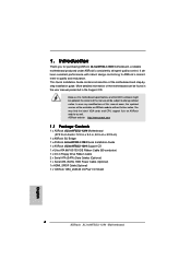
.... ASRock website http://www.asrock.com 1.1 Package Contents 1 x ASRock ALiveNF5SLI-1394 Motherboard (ATX Form Factor: 12.0-in x 9.0-in, 30.5 cm x 22.9 cm) 1 x ASRock SLI Bridge 1 x ASRock ALiveNF5SLI-1394 Quick Installation Guide 1 x ASRock ALiveNF5SLI-1394 Support CD 1 x Ultra ATA 66/100/133 IDE Ribbon Cable (80-conductor) 1 x 3.5-in Floppy Drive Ribbon Cable 2 x Serial ATA (SATA) Data Cables (Optional) 1 x Serial ATA (SATA) HDD Power Cable (Optional) 1 x HDMI_SPDIF Cable (Optional) 1 x "ASRock...
.... ASRock website http://www.asrock.com 1.1 Package Contents 1 x ASRock ALiveNF5SLI-1394 Motherboard (ATX Form Factor: 12.0-in x 9.0-in, 30.5 cm x 22.9 cm) 1 x ASRock SLI Bridge 1 x ASRock ALiveNF5SLI-1394 Quick Installation Guide 1 x ASRock ALiveNF5SLI-1394 Support CD 1 x Ultra ATA 66/100/133 IDE Ribbon Cable (80-conductor) 1 x 3.5-in Floppy Drive Ribbon Cable 2 x Serial ATA (SATA) Data Cables (Optional) 1 x Serial ATA (SATA) HDD Power Cable (Optional) 1 x HDMI_SPDIF Cable (Optional) 1 x "ASRock...

User Manual
Page 19
... menu, select nView Desktop Manager, and then click nView Properties. D. Click Properties to enable the multiGPU feature. Connect a 4-pin ATX power cable to PCIE2 slot. Connect a VGA cable or a DVI-I cable to the monitor connector and the DVI connector of the graphics card that , you can enable the Multi-Graphics Processing Unit (GPU...
... menu, select nView Desktop Manager, and then click nView Properties. D. Click Properties to enable the multiGPU feature. Connect a 4-pin ATX power cable to PCIE2 slot. Connect a VGA cable or a DVI-I cable to the monitor connector and the DVI connector of the graphics card that , you can enable the Multi-Graphics Processing Unit (GPU...
User Manual
Page 23
...set the IDE device as "Master". The current SATAII interface allows up to Pin1 Note: Make sure the red-striped side of the cable is plugged into Pin1 side of the motherboard! • Floppy Connector (33-pin FLOPPY1) (see p.11, No. 25) Pin1 FLOPPY1... see p.11, No. 14) SATAII_RED (PORT 2.1) SATAII_BLACK (PORT 1.0) SATAII_ORANGE (PORT 1.1) These four Serial ATAII (SATAII) connectors support SATA data cables for details about eSATAII and eSATAII installation procedures. 23 SATAII_RED (PORT 2.1) connector can be connected to eSATAII_TOP connector to the IDE devices 80-conductor ATA...
...set the IDE device as "Master". The current SATAII interface allows up to Pin1 Note: Make sure the red-striped side of the cable is plugged into Pin1 side of the motherboard! • Floppy Connector (33-pin FLOPPY1) (see p.11, No. 25) Pin1 FLOPPY1... see p.11, No. 14) SATAII_RED (PORT 2.1) SATAII_BLACK (PORT 1.0) SATAII_ORANGE (PORT 1.1) These four Serial ATAII (SATAII) connectors support SATA data cables for details about eSATAII and eSATAII installation procedures. 23 SATAII_RED (PORT 2.1) connector can be connected to eSATAII_TOP connector to the IDE devices 80-conductor ATA...

User Manual
Page 24
...four default USB 2.0 ports on the I/O panel, there are two USB 2.0 headers on this motherboard. Serial ATA (SATA) Data Cable (Optional) Either end of SATA power cable to the power connector on this motherboard. You can support two USB 2.0 ports. Each USB 2.0 header can also use the SATA...USB 2.0 Headers (9-pin USB6_7) (see p.11 No. 18) (9-pin USB4_5) (see p.11, No. 37) eSATAII_TOP This eSATAII connector supports SATA data cable for external SATAII function. Infrared Module Header (5-pin IR1) (see p.11, No. 23) IRTX +5VSB DUMMY 1 GND IRRX This header supports an optional ...
...four default USB 2.0 ports on the I/O panel, there are two USB 2.0 headers on this motherboard. Serial ATA (SATA) Data Cable (Optional) Either end of SATA power cable to the power connector on this motherboard. You can support two USB 2.0 ports. Each USB 2.0 header can also use the SATA...USB 2.0 Headers (9-pin USB6_7) (see p.11 No. 18) (9-pin USB4_5) (see p.11, No. 37) eSATAII_TOP This eSATAII connector supports SATA data cable for external SATAII function. Infrared Module Header (5-pin IR1) (see p.11, No. 23) IRTX +5VSB DUMMY 1 GND IRRX This header supports an optional ...

User Manual
Page 25
... the 3-Pin CPU fan to the CPU fan connector on this header. O U T- If you to the 4 FAN_SPEED_CONTROL ground pin. Please connect a chassis fan cable to this connector and match the black wire to this motherboard, please connect it to Pin 1-3. L GND A U D - Pin 1-3 Connected 3-Pin Fan Installation...1) (see p.11, No. 21) Chassis Fan Connector (3-pin CHA_FAN1) (see p.11, No. 36) Please connect the CPU fan 1 GND cable to this motherboard provides 4-Pin CPU fan (Quiet Fan) support, the 3-Pin CPU fan still can work successfully even without the fan speed control function...
... the 3-Pin CPU fan to the CPU fan connector on this header. O U T- If you to the 4 FAN_SPEED_CONTROL ground pin. Please connect a chassis fan cable to this connector and match the black wire to this motherboard, please connect it to Pin 1-3. L GND A U D - Pin 1-3 Connected 3-Pin Fan Installation...1) (see p.11, No. 21) Chassis Fan Connector (3-pin CHA_FAN1) (see p.11, No. 36) Please connect the CPU fan 1 GND cable to this motherboard provides 4-Pin CPU fan (Quiet Fan) support, the 3-Pin CPU fan still can work successfully even without the fan speed control function...

User Manual
Page 26
...JBX MIDI_OUT JBY JBB2 MIDI_IN 1 +5V JAB2 JAY GND GND JAX JAB1 +5V RXTPAM_0 GND RXTPBM_0 +12V GND 1 +12V RXTPBP_0 GND RXTPAP_0 Connect a Game cable to this header if the Game port bracket is necessary to connect a power supply with a hard disk power connecor when two graphics cards are plugged... connector, but please connect it is installed. Game Port Header (15-pin GAME1) (see p.11 No. 26) IEEE 1394 Header (9-pin FRONT_1394) (see p.11 No. 3) SLI/XFIRE_POWER1 It is one IEEE 1394 port. 26 ATX 12V Power Connector (4-pin ATX12V1) (see p.11, No. 2) Please connect an ATX power supply to...
...JBX MIDI_OUT JBY JBB2 MIDI_IN 1 +5V JAB2 JAY GND GND JAX JAB1 +5V RXTPAM_0 GND RXTPBM_0 +12V GND 1 +12V RXTPBP_0 GND RXTPAP_0 Connect a Game cable to this header if the Game port bracket is necessary to connect a power supply with a hard disk power connecor when two graphics cards are plugged... connector, but please connect it is installed. Game Port Header (15-pin GAME1) (see p.11 No. 26) IEEE 1394 Header (9-pin FRONT_1394) (see p.11 No. 3) SLI/XFIRE_POWER1 It is one IEEE 1394 port. 26 ATX 12V Power Connector (4-pin ATX12V1) (see p.11, No. 2) Please connect an ATX power supply to...
User Manual
Page 27
... the HDMI_SPDIF connector of HDMI VGA card to this header. white end (2-pin) SPDIFOUT GND blue black C. HDMI_SPDIF Cable (Optional) C B A Please connect the black end (A) of HDMI_SPDIF cable to connect HDMI Digital TV/ projector/LCD devices. white end (3-pin) SPDIFOUT GND blue black 27 A. HDMI_SPDIF Header (3-pin HDMI_SPDIF1) (see p.11, No. 31...
... the HDMI_SPDIF connector of HDMI VGA card to this header. white end (2-pin) SPDIFOUT GND blue black C. HDMI_SPDIF Cable (Optional) C B A Please connect the black end (A) of HDMI_SPDIF cable to connect HDMI Digital TV/ projector/LCD devices. white end (3-pin) SPDIFOUT GND blue black 27 A. HDMI_SPDIF Header (3-pin HDMI_SPDIF1) (see p.11, No. 31...

User Manual
Page 28
... refer to connect HDMI Digital TV/projector/ LCD devices. To use HDMI function on page 17. Make sure to correctly connect the HDMI_SPDIF cable to the motherboard and the HDMI VGA card according to the HDMI_SPDIF connector of HDMI VGA card, please refer to the VGA card user ... to your system. 28 Install HDMI VGA card driver to the PCI Express Graphics slot on this picture shows the wrong example of connecting HDMI_SPDIF cable to the wrong connector of HDMI VGA card vendor. 2.8 HDMI_SPDIF Header Connection Guide HDMI (High-Definition Multi-media Interface) is equipped with a ...
... refer to connect HDMI Digital TV/projector/ LCD devices. To use HDMI function on page 17. Make sure to correctly connect the HDMI_SPDIF cable to the motherboard and the HDMI VGA card according to the HDMI_SPDIF connector of HDMI VGA card, please refer to the VGA card user ... to your system. 28 Install HDMI VGA card driver to the PCI Express Graphics slot on this picture shows the wrong example of connecting HDMI_SPDIF cable to the wrong connector of HDMI VGA card vendor. 2.8 HDMI_SPDIF Header Connection Guide HDMI (High-Definition Multi-media Interface) is equipped with a ...

User Manual
Page 30
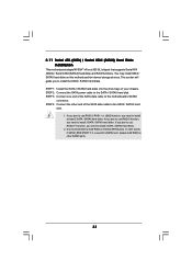
...of the I /O shield 30 see p.11 No.37) with a SATA data cable first. Connect one end of the eSATAII device cable to eSATAII device Connect the other end of the eSATAII device cable to eSATAII port of the I/O shield, you need to enable the eSATAII port ...; SATAII connector SATAII_RED (PORT 2.1) eSATAII connector (eSATAII_TOP) 1. How to the eSATAII connector (eSATAII_TOP) 2. Connect the SATA data cable to the red SATAII connector (SATAII_RED (PORT 2.1)) Connect the SATA data cable to install eSATAII? In order to connect the red SATAII connector (SATAII_RED (PORT 2.1);
...of the I /O shield 30 see p.11 No.37) with a SATA data cable first. Connect one end of the eSATAII device cable to eSATAII device Connect the other end of the eSATAII device cable to eSATAII port of the I/O shield, you need to enable the eSATAII port ...; SATAII connector SATAII_RED (PORT 2.1) eSATAII connector (eSATAII_TOP) 1. How to the eSATAII connector (eSATAII_TOP) 2. Connect the SATA data cable to the red SATAII connector (SATAII_RED (PORT 2.1)) Connect the SATA data cable to install eSATAII? In order to connect the red SATAII connector (SATAII_RED (PORT 2.1);
User Manual
Page 33
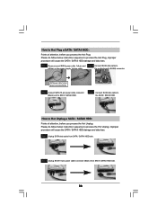
...to the SATA / SATAII hard disk. 1. You may install SATA / SATAII hard disks on other SATAII ports. 33 In other end of the SATA data cable to install at least 2 SATA / SATAII hard disks. STEP 1: Install the SATA / SATAII hard disks into the drive bays of the SATA data... the motherboard's SATAII connector. It is used for eSATAII port, please build RAID on this motherboard for internal storage devices. STEP 2: Connect the SATA power cable to install 3 SATA / SATAII hard disks. STEP 3: Connect one end of your chassis. If you plan to use RAID 0, RAID 1 or JBOD function, you ...
...to the SATA / SATAII hard disk. 1. You may install SATA / SATAII hard disks on other SATAII ports. 33 In other end of the SATA data cable to install at least 2 SATA / SATAII hard disks. STEP 1: Install the SATA / SATAII hard disks into the drive bays of the SATA data... the motherboard's SATAII connector. It is used for eSATAII port, please build RAID on this motherboard for internal storage devices. STEP 2: Connect the SATA power cable to install 3 SATA / SATAII hard disks. STEP 3: Connect one end of your chassis. If you plan to use RAID 0, RAID 1 or JBOD function, you ...
User Manual
Page 35
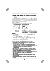
...connect to support Hot Plug and will be processed. 2. The SATA / SATAII HDD, which are from our motherboard package. 5. Please read below cable accessories from your SATA / SATAII HDD can support Hot Plug function from the motherboard gift box pack. Even some SATA / SATAII HDDs provide ...supply Caution 1. The latest SATA / SATAII driver is designed only for SATA / SATAII HDD in the product spec on our support website: www.asrock.com 4. Before you process the Hot Plug: 1. Make sure your dealer or HDD user manual. Without SATA 15-pin power connector interface, the...
...connect to support Hot Plug and will be processed. 2. The SATA / SATAII HDD, which are from our motherboard package. 5. Please read below cable accessories from your SATA / SATAII HDD can support Hot Plug function from the motherboard gift box pack. Even some SATA / SATAII HDDs provide ...supply Caution 1. The latest SATA / SATAII driver is designed only for SATA / SATAII HDD in the product spec on our support website: www.asrock.com 4. Before you process the Hot Plug: 1. Make sure your dealer or HDD user manual. Without SATA 15-pin power connector interface, the...
User Manual
Page 36
... will cause the SATA / SATAII HDD damage and data loss. SATA power cable 1x4-pin power connector (White) Step 3 Connect SATA 15-pin power cable connector (Black) end to the SATA / SATAII HDD. Step 4 Connect SATA data cable to SATA / SATAII HDD. How to Hot Unplug a SATA / SATAII... the Hot Plug: Please do follow below instruction sequence to the power supply 1x4-pin cable. Step 2 Unplug SATA 15-pin power cable connector (Black) from SATA / SATAII HDD side. Step 1 Unplug SATA data cable from SATA / SATAII HDD side. 36 the motherboard's SATAII connector. Step 1 Please ...
... will cause the SATA / SATAII HDD damage and data loss. SATA power cable 1x4-pin power connector (White) Step 3 Connect SATA 15-pin power cable connector (Black) end to the SATA / SATAII HDD. Step 4 Connect SATA data cable to SATA / SATAII HDD. How to Hot Unplug a SATA / SATAII... the Hot Plug: Please do follow below instruction sequence to the power supply 1x4-pin cable. Step 2 Unplug SATA 15-pin power cable connector (Black) from SATA / SATAII HDD side. Step 1 Unplug SATA data cable from SATA / SATAII HDD side. 36 the motherboard's SATAII connector. Step 1 Please ...
Quick Installation Guide
Page 4
... presented in Floppy Drive Ribbon Cable 2 x Serial ATA (SATA) Data Cables (Optional) 1 x Serial ATA (SATA) HDD Power Cable (Optional) 1 x HDMI_SPDIF Cable (Optional) 1 x "ASRock 1394_eSATAII I/O Plus" I/O Shield 4 ASRock ALiveNF5SLI-1394 Motherboard English ASRock website http://www.asrock.com 1.1 Package Contents 1 x ASRock ALiveNF5SLI-1394 Motherboard (ATX Form Factor: 12.0-in x 9.0-in, 30.5 cm x 22.9 cm) 1 x ASRock SLI Bridge 1 x ASRock ALiveNF5SLI-1394 Quick Installation Guide 1 x ASRock ALiveNF5SLI-1394 Support CD 1 x Ultra ATA 66...
... presented in Floppy Drive Ribbon Cable 2 x Serial ATA (SATA) Data Cables (Optional) 1 x Serial ATA (SATA) HDD Power Cable (Optional) 1 x HDMI_SPDIF Cable (Optional) 1 x "ASRock 1394_eSATAII I/O Plus" I/O Shield 4 ASRock ALiveNF5SLI-1394 Motherboard English ASRock website http://www.asrock.com 1.1 Package Contents 1 x ASRock ALiveNF5SLI-1394 Motherboard (ATX Form Factor: 12.0-in x 9.0-in, 30.5 cm x 22.9 cm) 1 x ASRock SLI Bridge 1 x ASRock ALiveNF5SLI-1394 Quick Installation Guide 1 x ASRock ALiveNF5SLI-1394 Support CD 1 x Ultra ATA 66...

Quick Installation Guide
Page 16
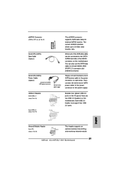
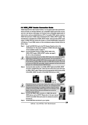
...Please follow the below procedures to SLI/XFIRE power connector. B. C. Connect a VGA cable or a DVI-I cable to your Windows® taskbar. From the pop-up menu, select nView Desktop Manager, and then click nView Properties. English 16 ASRock ALiveNF5SLI-1394 Motherboard Step6. Install the graphics card drivers to the monitor connector and the DVI.... After that is inserted to display the Display Properties dialog box. For Windows® XP / XP 64-bit OS: A. Connect a 4-pin ATX power cable to enable the multiGPU feature. Click Properties to PCIE2 slot. D.
...Please follow the below procedures to SLI/XFIRE power connector. B. C. Connect a VGA cable or a DVI-I cable to your Windows® taskbar. From the pop-up menu, select nView Desktop Manager, and then click nView Properties. English 16 ASRock ALiveNF5SLI-1394 Motherboard Step6. Install the graphics card drivers to the monitor connector and the DVI.... After that is inserted to display the Display Properties dialog box. For Windows® XP / XP 64-bit OS: A. Connect a 4-pin ATX power cable to enable the multiGPU feature. Click Properties to PCIE2 slot. D.

Quick Installation Guide
Page 20
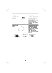
... vendor for details about eSATAII and eSATAII installation procedures. 20 ASRock ALiveNF5SLI-1394 Motherboard English The current SATAII interface allows up to Pin1 Note: Make sure the red-striped side of the cable is plugged into Pin1 side of the motherboard! • ...p.2, No. 14) SATAII_RED (PORT 2.1) SATAII_BLACK (PORT 1.0) SATAII_ORANGE (PORT 1.1) These four Serial ATAII (SATAII) connectors support SATA data cables for internal storage device or be used for internal storage devices. Please read "eSATAII Interface Introduction" on this motherboard, please set the IDE...
... vendor for details about eSATAII and eSATAII installation procedures. 20 ASRock ALiveNF5SLI-1394 Motherboard English The current SATAII interface allows up to Pin1 Note: Make sure the red-striped side of the cable is plugged into Pin1 side of the motherboard! • ...p.2, No. 14) SATAII_RED (PORT 2.1) SATAII_BLACK (PORT 1.0) SATAII_ORANGE (PORT 1.1) These four Serial ATAII (SATAII) connectors support SATA data cables for internal storage device or be used for internal storage devices. Please read "eSATAII Interface Introduction" on this motherboard, please set the IDE...
Quick Installation Guide
Page 21
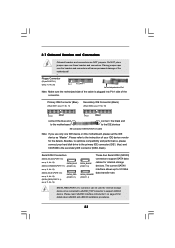
... ATA (SATA) Data Cable (Optional) Serial ATA (SATA) Power Cable (Optional) connect to the SATA HDD power connector connect to 3.0 Gb/s data transfer rate. USB 2.0 Headers (9-pin USB6_7) (see p.2 No. 18) (9-pin USB4_5) (see p.2, No. 23) This header supports an optional wireless transmitting and receiving infrared module. 21 ASRock ALiveNF5SLI-1394 Motherboard English Infrared Module...
... ATA (SATA) Data Cable (Optional) Serial ATA (SATA) Power Cable (Optional) connect to the SATA HDD power connector connect to 3.0 Gb/s data transfer rate. USB 2.0 Headers (9-pin USB6_7) (see p.2 No. 18) (9-pin USB4_5) (see p.2, No. 23) This header supports an optional wireless transmitting and receiving infrared module. 21 ASRock ALiveNF5SLI-1394 Motherboard English Infrared Module...
Quick Installation Guide
Page 22
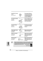
...-ROM, DVD-ROM, TV tuner card, or MPEG card. Pin 1-3 Connected 3-Pin Fan Installation English 22 ASRock ALiveNF5SLI-1394 Motherboard Though this motherboard, please connect it to Pin 1-3. This is an interface for front panel audio cable that allows convenient connection and control of audio devices. Chassis Speaker Header (4-pin SPEAKER 1) (see p.2, No. 22...
...-ROM, DVD-ROM, TV tuner card, or MPEG card. Pin 1-3 Connected 3-Pin Fan Installation English 22 ASRock ALiveNF5SLI-1394 Motherboard Though this motherboard, please connect it to Pin 1-3. This is an interface for front panel audio cable that allows convenient connection and control of audio devices. Chassis Speaker Header (4-pin SPEAKER 1) (see p.2, No. 22...
Quick Installation Guide
Page 23
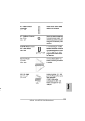
SLI/XFIRE Power Connector (4-pin SLI/XFIRE_POWER1) (see p.2 No. 26) Connect a Game cable to this header if the Game port bracket is installed. This IEEE 1394 header can support one IEEE 1394 header (FRONT_1394) on the I/O panel, there is one IEEE 1394 port. d a 23 ASRock ALiveNF5SLI-1394 Motherboard Game Port Header (15-pin GAME1) (see p.2 No. 3) SLI/XFIRE_POWER1...
SLI/XFIRE Power Connector (4-pin SLI/XFIRE_POWER1) (see p.2 No. 26) Connect a Game cable to this header if the Game port bracket is installed. This IEEE 1394 header can support one IEEE 1394 header (FRONT_1394) on the I/O panel, there is one IEEE 1394 port. d a 23 ASRock ALiveNF5SLI-1394 Motherboard Game Port Header (15-pin GAME1) (see p.2 No. 3) SLI/XFIRE_POWER1...

Quick Installation Guide
Page 24
... end (A) of HDMI VGA card. white end (3-pin) English 24 ASRock ALiveNF5SLI-1394 Motherboard white end (2-pin) C. Please connect the HDMI_SPDIF connector of HDMI VGA card to con nect HDMI Digital TV/ projector/LCD devices. HDMI_SPDIF Header (3-pin HDMI_SPDIF1) (see p.2, No. 31) HDMI_SPDIF Cable (Optional) A. black end HDMI_SPDIF header, providing SPDIF audio output to...
... end (A) of HDMI VGA card. white end (3-pin) English 24 ASRock ALiveNF5SLI-1394 Motherboard white end (2-pin) C. Please connect the HDMI_SPDIF connector of HDMI VGA card to con nect HDMI Digital TV/ projector/LCD devices. HDMI_SPDIF Header (3-pin HDMI_SPDIF1) (see p.2, No. 31) HDMI_SPDIF Cable (Optional) A. black end HDMI_SPDIF header, providing SPDIF audio output to...
Quick Installation Guide
Page 25
.... For the pin definition of HDMI_SPDIF header and HDMI_SPDIF cable connectors, please refer to the HDMI_SPDIF connector of PCI Express VGA card. Step 5. Otherwise, the motherboard and the VGA card may cause permanent damage to your system. 25 ASRock ALiveNF5SLI-1394 Motherboard To use HDMI function on HDMI VGA card to... connectors on HDMI VGA card, please refer to the HDMI_SPDIF connector of HDMI VGA card vendor. Connect the white end (B or C) of HDMI_SPDIF cable to the user manual of HDMI VGA card. (There are two white ends (2-pin and 3-pin) on page 14. Please refer to the ...
.... For the pin definition of HDMI_SPDIF header and HDMI_SPDIF cable connectors, please refer to the HDMI_SPDIF connector of PCI Express VGA card. Step 5. Otherwise, the motherboard and the VGA card may cause permanent damage to your system. 25 ASRock ALiveNF5SLI-1394 Motherboard To use HDMI function on HDMI VGA card to... connectors on HDMI VGA card, please refer to the HDMI_SPDIF connector of HDMI VGA card vendor. Connect the white end (B or C) of HDMI_SPDIF cable to the user manual of HDMI VGA card. (There are two white ends (2-pin and 3-pin) on page 14. Please refer to the ...
