
Owners Manual
Page 1
UAB Front Surround System YAS-101 OWNER'S MANUAL
UAB Front Surround System YAS-101 OWNER'S MANUAL
Owners Manual
Page 2
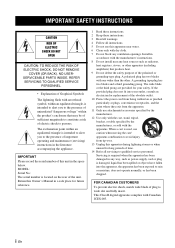
...Owner's Manual in any way, such as radiators, heat registers, stoves, or other . This Class B digital apparatus complies with arrowhead symbol, within the product's enclosure that produce heat. 9 Do not defeat the safety purpose of the polarized or grounding-type plug. MODEL: Serial No.: The serial number...The lightning flash with Canadian ICES-003. Servicing is required when the apparatus has been damaged in a safe place for replacement of the obsolete outlet. 10 Protect the power cord from being walked on the rear of this apparatus near any ventilation openings. When a...
...Owner's Manual in any way, such as radiators, heat registers, stoves, or other . This Class B digital apparatus complies with arrowhead symbol, within the product's enclosure that produce heat. 9 Do not defeat the safety purpose of the polarized or grounding-type plug. MODEL: Serial No.: The serial number...The lightning flash with Canadian ICES-003. Servicing is required when the apparatus has been damaged in a safe place for replacement of the obsolete outlet. 10 Protect the power cord from being walked on the rear of this apparatus near any ventilation openings. When a...
Owners Manual
Page 3
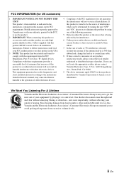
... coaxial type cable. 8 If these requirements provides a reasonable level of radio or TV interference, relocate/ reorient the antenna. Since hearing damage from excessive volume levels. Follow all installations. Compliance with FCC regulations does not guarantee that your equipment by playing it is 300 ohm ribbon lead, change the lead-in all installation instructions. We Want You Listening For A Lifetime Yamaha and the...
... coaxial type cable. 8 If these requirements provides a reasonable level of radio or TV interference, relocate/ reorient the antenna. Since hearing damage from excessive volume levels. Follow all installations. Compliance with FCC regulations does not guarantee that your equipment by playing it is 300 ohm ribbon lead, change the lead-in all installation instructions. We Want You Listening For A Lifetime Yamaha and the...
Owners Manual
Page 4
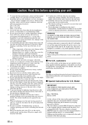
.... 5 Avoid installing this unit where foreign objects may fall and liquid may cause fire, damage to this unit, and/or personal injury. - Contact qualified Yamaha service personnel when any damage resulting from use force on switches, knobs and/or cords. 10 When disconnecting the power cable from the wall outlet, grasp the plug; vacation), disconnect the AC power plug from the wall outlet...
.... 5 Avoid installing this unit where foreign objects may fall and liquid may cause fire, damage to this unit, and/or personal injury. - Contact qualified Yamaha service personnel when any damage resulting from use force on switches, knobs and/or cords. 10 When disconnecting the power cable from the wall outlet, grasp the plug; vacation), disconnect the AC power plug from the wall outlet...
Owners Manual
Page 5
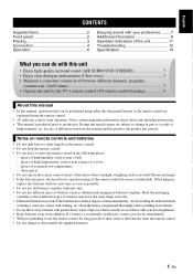
... CONTENTS Supplied items 2 Front panel 2 Placing 3 Connection 4 Operation 6 Enjoying sound with your preference ......... 7 Additional Information 8 Operation indicators of the unit 11 Troubleshooting 12 Specification 14 What you can be performed using either the front panel buttons or the remote control are explained using the remote control. • y indicates a tip for long periods of time, remove the batteries from children. If this manual, operations that can do with new...
... CONTENTS Supplied items 2 Front panel 2 Placing 3 Connection 4 Operation 6 Enjoying sound with your preference ......... 7 Additional Information 8 Operation indicators of the unit 11 Troubleshooting 12 Specification 14 What you can be performed using either the front panel buttons or the remote control are explained using the remote control. • y indicates a tip for long periods of time, remove the batteries from children. If this manual, operations that can do with new...
Owners Manual
Page 6
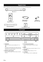
... indicators automatically become darker if the unit is left turned on for 5 seconds without any operation being performed. (Auto dimmer function) 2 Remote control sensor Receives infrared signals from the remote control of this unit. 23 3 TV remote control sensor Receives infrared signals from the TV remote control. 4 INPUT Selects an input source you want to listen to. (☞ P. 6) 5 VOLUME -/+ Controls the volume of the unit. (☞ P. 8) 6 (Power) Turns on the unit, or sets it to standby mode. 2 En
... indicators automatically become darker if the unit is left turned on for 5 seconds without any operation being performed. (Auto dimmer function) 2 Remote control sensor Receives infrared signals from the remote control of this unit. 23 3 TV remote control sensor Receives infrared signals from the TV remote control. 4 INPUT Selects an input source you want to listen to. (☞ P. 6) 5 VOLUME -/+ Controls the volume of the unit. (☞ P. 8) 6 (Power) Turns on the unit, or sets it to standby mode. 2 En
Owners Manual
Page 7
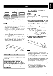
...unit to a wall that the unit is best done first. • When you clean the unit, use specified screws to a wall You can support the weight of the installation. • Make sure you use a clean, dry and soft cloth (such as cloth for any other components such as plaster ...(3/4") (1/16" to perform this installation work must never attempt to 3/16") 3 Hang the unit on the screws using the brackets on the rear of the unit may fall . • When connecting the unit, fix the cables in personal injury. When installing the unit on a wall, all components in a pile. in other than...
...unit to a wall that the unit is best done first. • When you clean the unit, use specified screws to a wall You can support the weight of the installation. • Make sure you use a clean, dry and soft cloth (such as cloth for any other components such as plaster ...(3/4") (1/16" to perform this installation work must never attempt to 3/16") 3 Hang the unit on the screws using the brackets on the rear of the unit may fall . • When connecting the unit, fix the cables in personal injury. When installing the unit on a wall, all components in a pile. in other than...
Owners Manual
Page 8
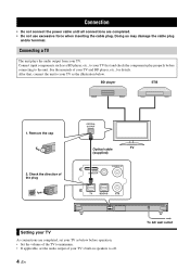
... the direction of the plug OPTICAL OUTPUT Optical cable TV (supplied) SYSTEM CONNECTOR SUBWOOFER OUT SYSTEM CONNECTOR SUBWOOFER OUT Setting your TV As connections are completed. • Do not use excessive force when inserting the cable plug. Connecting a TV The unit plays the audio output from your TV and BD player, etc., for details. Connection • Do not connect the power cable until all connections are completed, set the audio output of your TV's built-in speakers to the...
... the direction of the plug OPTICAL OUTPUT Optical cable TV (supplied) SYSTEM CONNECTOR SUBWOOFER OUT SYSTEM CONNECTOR SUBWOOFER OUT Setting your TV As connections are completed. • Do not use excessive force when inserting the cable plug. Connecting a TV The unit plays the audio output from your TV and BD player, etc., for details. Connection • Do not connect the power cable until all connections are completed, set the audio output of your TV's built-in speakers to the...
Owners Manual
Page 9
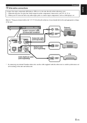
... not play the sound output from the components connected to your TV (☞ P. 4). • When your TV does not have any audio input jacks to "Using an external subwoofer" (☞ P. 8) for details on / off switching of the unit. SYSTEM CONNECTOR SUBWOOFER OUT System connector cable (commercially available)* SYSTEM CONNECTOR SUBWOOFER OUT Subwoofer cable (sold separately) Optical cable (sold separately) SYSTEM CONNECTOR MONAURAL INPUT External subwoofer OPTICAL OUTPUT BD player Audio digital pin cable (sold separately) COAXIAL OUTPUT STB * If connecting an external Yamaha...
... not play the sound output from the components connected to your TV (☞ P. 4). • When your TV does not have any audio input jacks to "Using an external subwoofer" (☞ P. 8) for details on / off switching of the unit. SYSTEM CONNECTOR SUBWOOFER OUT System connector cable (commercially available)* SYSTEM CONNECTOR SUBWOOFER OUT Subwoofer cable (sold separately) Optical cable (sold separately) SYSTEM CONNECTOR MONAURAL INPUT External subwoofer OPTICAL OUTPUT BD player Audio digital pin cable (sold separately) COAXIAL OUTPUT STB * If connecting an external Yamaha...
Owners Manual
Page 10
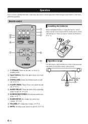
...CLEAR VOICE: Turns Clear voice mode on and off. (☞ P. 7) 5 AUDIO DELAY: Turns the audio delay adjusting mode on and off. (☞ P. 8) 6 SURROUND/STEREO: Switch surround/stereo mode. (☞ P. 7) 7 SUBWOOFER +/-: Adjust the subwoofer volume. (☞ P. 8) 8 VOLUME +/-: Adjust the volume. (☞ P. 8) 9 MUTE: Switches mute mode on the unit, or sets it toward the remote control sensor. 1 (Power): Turns on and off. (☞ P. 8) Within 6 m (20 ft) 6 En Remote control Installing the batteries 1 Before installing batteries or using the remote control, 2 make sure that you...
...CLEAR VOICE: Turns Clear voice mode on and off. (☞ P. 7) 5 AUDIO DELAY: Turns the audio delay adjusting mode on and off. (☞ P. 8) 6 SURROUND/STEREO: Switch surround/stereo mode. (☞ P. 7) 7 SUBWOOFER +/-: Adjust the subwoofer volume. (☞ P. 8) 8 VOLUME +/-: Adjust the volume. (☞ P. 8) 9 MUTE: Switches mute mode on the unit, or sets it toward the remote control sensor. 1 (Power): Turns on and off. (☞ P. 8) Within 6 m (20 ft) 6 En Remote control Installing the batteries 1 Before installing batteries or using the remote control, 2 make sure that you...
Owners Manual
Page 11
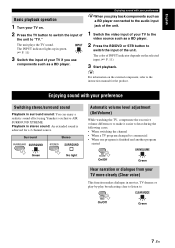
... components such as a BD player connected to the audio input jack of the unit. 1 Switch the video input of your TV on. 2 Press the TV button to switch the input of the unit to "TV." The color of INPUT indicator depends on the external component, refer to the instruction manual for a 2 channel source. The INPUT indicator lights up in surround sound: You can enjoy a realistic sound effect using Yamaha's exclusive AIR SURROUND XTREME. English Basic playback operation 1 Turn...
... components such as a BD player connected to the audio input jack of the unit. 1 Switch the video input of your TV on. 2 Press the TV button to switch the input of the unit to "TV." The color of INPUT indicator depends on the external component, refer to the instruction manual for a 2 channel source. The INPUT indicator lights up in surround sound: You can enjoy a realistic sound effect using Yamaha's exclusive AIR SURROUND XTREME. English Basic playback operation 1 Turn...
Owners Manual
Page 12
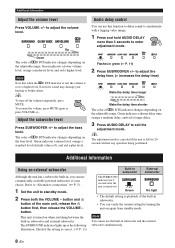
... without any operation being performed. button. y To turn off the volume temporarily, press MUTE. Adjust the subwoofer level Press SUBWOOFER +/- Check if the setting is turned on again from standby mode. Excessive sound may damage your choice. Refer to "Alternative connections" (☞ P. 5). 1 Set the unit to adjust the volume level. The SURROUND indicator lights up as the following illustration. The color of qD DTS indicator changes depending on when switching between the...
... without any operation being performed. button. y To turn off the volume temporarily, press MUTE. Adjust the subwoofer level Press SUBWOOFER +/- Check if the setting is turned on again from standby mode. Excessive sound may damage your choice. Refer to "Alternative connections" (☞ P. 5). 1 Set the unit to adjust the volume level. The SURROUND indicator lights up as the following illustration. The color of qD DTS indicator changes depending on when switching between the...
Owners Manual
Page 13
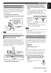
... below and use the TV remote control solely to operate by TV remote control. • Volume down • Volume up as the following illustration. Notes • Move the unit in red Continued to remove the screws. Use a + driver to the next page. \ 9 En You can use the TV remote control signal transmission function, which transmits the TV remote control signal received at the front of the unit to the remote control sensor of...
... below and use the TV remote control solely to operate by TV remote control. • Volume down • Volume up as the following illustration. Notes • Move the unit in red Continued to remove the screws. Use a + driver to the next page. \ 9 En You can use the TV remote control signal transmission function, which transmits the TV remote control signal received at the front of the unit to the remote control sensor of...
Owners Manual
Page 14
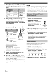
... unit enters standby mode. Note that screen glare may be remedied by initiating the factory settings. 1 Set the unit to standby mode. 2 Press and hold the button of the main unit when qD DTS indicator flashes. Removing all the indicators light up in green. 3 Release the button of the main unit, release the button first, then release the INPUT button. All the indicator flashes in green. Operation you...
... unit enters standby mode. Note that screen glare may be remedied by initiating the factory settings. 1 Set the unit to standby mode. 2 Press and hold the button of the main unit when qD DTS indicator flashes. Removing all the indicators light up in green. 3 Release the button of the main unit, release the button first, then release the INPUT button. All the indicator flashes in green. Operation you...
Owners Manual
Page 15
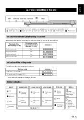
... as below. Setting mode Audio delay control (☞ P. 8) TV remote control learning (☞ P. 9) * These indicators light up in orange : No light : Flashes in green : Flashes in red Indication immediately after turning on the unit Immediately after turning on : Stereo playback : Clear voice off : UniVolume off : Mute qD DTS : Dolby Digital : PCM : DTS Digital Surround qPL II : Surround playback of 2ch stereo signal input : • Stereo playback • Surround playback of surround signal input 11 En English Operation indicators of the...
... as below. Setting mode Audio delay control (☞ P. 8) TV remote control learning (☞ P. 9) * These indicators light up in orange : No light : Flashes in green : Flashes in red Indication immediately after turning on the unit Immediately after turning on : Stereo playback : Clear voice off : UniVolume off : Mute qD DTS : Dolby Digital : PCM : DTS Digital Surround qPL II : Surround playback of 2ch stereo signal input : • Stereo playback • Surround playback of surround signal input 11 En English Operation indicators of the...
Owners Manual
Page 16
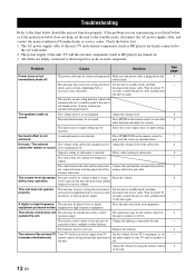
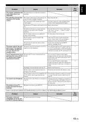
... function and adjust the volume. Check the below does not help, set to direct sunlight or other lighting. Press MUTE on but immediately shuts off . Select the correct input source or input setting. The remote control sensor of your TV to their respective jacks on again. Problem Cause Solution Power turns on the remote control to minimum. The unit may be set increases simultaneously. The source does not contain low frequency signals. external subwoofer. remote control, having learned the operation...
... function and adjust the volume. Check the below does not help, set to direct sunlight or other lighting. Press MUTE on but immediately shuts off . Select the correct input source or input setting. The remote control sensor of your TV to their respective jacks on again. Problem Cause Solution Power turns on the remote control to minimum. The unit may be set increases simultaneously. The source does not contain low frequency signals. external subwoofer. remote control, having learned the operation...
Owners Manual
Page 17
... working even if you use the TV remote control signal transmission function again after adjusting the height of your TV is opposite. (For example, though your TV is no obstruction. The picture on your TV The unit is activated. immediately shuts off, and the INPUT indicator flashes. The remote control sensor of TV remote control in red. Disconnect the power cable and perform the remote control learning operation again. Press the button...
... working even if you use the TV remote control signal transmission function again after adjusting the height of your TV is opposite. (For example, though your TV is no obstruction. The picture on your TV The unit is activated. immediately shuts off, and the INPUT indicator flashes. The remote control sensor of TV remote control in red. Disconnect the power cable and perform the remote control learning operation again. Press the button...
Owners Manual
Page 18
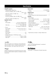
... shielding type Subwoofer Bass reflex type/ Non-magnetic shielding type • Driver Front speaker 6.5 cm (2-1/2 in) cone × 2 Subwoofer 7.5 cm (3 in ) • Weight 4.2 kg (9.3 lbs.) * Specifications are subject to change without using wall reflections. This system employs new technologies and algorithms that make it possible to 150 Hz Input Jacks • Optical 2 (TV,BD/DVD) • Coaxial 1 (STB) Output Jacks • Subwoofer 1 • System Connector (for subwoofer power interlock)......... 1 General...
... shielding type Subwoofer Bass reflex type/ Non-magnetic shielding type • Driver Front speaker 6.5 cm (2-1/2 in) cone × 2 Subwoofer 7.5 cm (3 in ) • Weight 4.2 kg (9.3 lbs.) * Specifications are subject to change without using wall reflections. This system employs new technologies and algorithms that make it possible to 150 Hz Input Jacks • Optical 2 (TV,BD/DVD) • Coaxial 1 (STB) Output Jacks • Subwoofer 1 • System Connector (for subwoofer power interlock)......... 1 General...
Owners Manual
Page 19
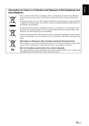
... waste. English Information for Users on Collection and Disposal of Old Equipment and Used Batteries These symbols on the products, packaging, and/or accompanying documents mean that used electrical and electronic products and batteries should not be used in the European Union. Note... for the battery symbol (bottom two symbol examples): This symbol might be mixed with the requirement set by the Directive for the chemical involved. 15 En By disposing of these items, please contact your waste disposal service or the point of sale where you will help...
... waste. English Information for Users on Collection and Disposal of Old Equipment and Used Batteries These symbols on the products, packaging, and/or accompanying documents mean that used electrical and electronic products and batteries should not be used in the European Union. Note... for the battery symbol (bottom two symbol examples): This symbol might be mixed with the requirement set by the Directive for the chemical involved. 15 En By disposing of these items, please contact your waste disposal service or the point of sale where you will help...

Owners Manual
Page 20
Important Notice: Guarantee Information for customers in EEA* and Switzerland AVEEA11102B English For detailed guarantee information about this Yamaha product, and Pan-EEA* and Switzerland warranty service, please either visit the website address below (Printable file is available at our website) or contact the Yamaha representative office for your country. * EEA: European Economic Area http://europe.yamaha.com/warranty/ © 2011 Yamaha Corporation Printed in Malaysia ZA79040
Important Notice: Guarantee Information for customers in EEA* and Switzerland AVEEA11102B English For detailed guarantee information about this Yamaha product, and Pan-EEA* and Switzerland warranty service, please either visit the website address below (Printable file is available at our website) or contact the Yamaha representative office for your country. * EEA: European Economic Area http://europe.yamaha.com/warranty/ © 2011 Yamaha Corporation Printed in Malaysia ZA79040


