

TL-SL1117 V2 QIG 7106503252
Page 4
CONTENTS Package Contents 1 Chapter 1 Introduction of the Product 1 1.1 Overview of the product 1 1.2 Features 2 Chapter 2 Installation 2 2.1 Mounting the Switch on a Desk 2 2.2 Mounting the Switch in a Rack 3 2.3 Mounting the SFP Module (for TL-SL1351 Only 4 2.4 Power on 4 Chapter 3 Identifying External Components 4 3.1 Front Panel 4 3.2 Rear Panel 5 Appendix A: Specifications 6
CONTENTS Package Contents 1 Chapter 1 Introduction of the Product 1 1.1 Overview of the product 1 1.2 Features 2 Chapter 2 Installation 2 2.1 Mounting the Switch on a Desk 2 2.2 Mounting the Switch in a Rack 3 2.3 Mounting the SFP Module (for TL-SL1351 Only 4 2.4 Power on 4 Chapter 3 Identifying External Components 4 3.1 Front Panel 4 3.2 Rear Panel 5 Appendix A: Specifications 6
TL-SL1117 V2 QIG 7106503252
Page 5
.... The TP-LINK TL-SL1210/TL-SL1117/TL-SL1226/TL-SL1351 features a nonblocking switching architecture that the package contains the above items. If any of the listed items are of TL-SL1351. 1.1 Overview of the product The TL-SL1210/TL-SL1117/TL-SL1226/TL-SL1351 Gigabit Switch provides you with your distributor. Increase the speed of the TL-SL1210 / TL-SL1117 / TL-SL1226 / TL-SL1351 Gigabit Switch. The TL-SL1210/TL-SL1117/TL-SL1226/TL-SL1351...
.... The TP-LINK TL-SL1210/TL-SL1117/TL-SL1226/TL-SL1351 features a nonblocking switching architecture that the package contains the above items. If any of the listed items are of TL-SL1351. 1.1 Overview of the product The TL-SL1210/TL-SL1117/TL-SL1226/TL-SL1351 Gigabit Switch provides you with your distributor. Increase the speed of the TL-SL1210 / TL-SL1117 / TL-SL1226 / TL-SL1351 Gigabit Switch. The TL-SL1210/TL-SL1117/TL-SL1226/TL-SL1351...
TL-SL1117 V2 QIG 7106503252
Page 6
...sure there is free space for monitoring power, link, activity, speed ¾ Internal power supply Chapter 2 Installation 2.1 Mounting the Switch on a Desk Before place the Switch on a desk, attach four rubber footpads to the flutes on the Switch bottom, then lay the Switch on the desktop, where can be have as...MDIX ¾ 2/1/2/2 10/100/1000Mbps Auto-Sense RJ45 ports supporting Auto-MDI/MDIX ¾ 1 SFP(Small Form Pluggable) module interface (For TL-SL1351 only) ¾ Supports Auto MDI / MDIX cable detection on all ports eliminate the need for crossover cable or Uplink port ¾ Non...
...sure there is free space for monitoring power, link, activity, speed ¾ Internal power supply Chapter 2 Installation 2.1 Mounting the Switch on a Desk Before place the Switch on a desk, attach four rubber footpads to the flutes on the Switch bottom, then lay the Switch on the desktop, where can be have as...MDIX ¾ 2/1/2/2 10/100/1000Mbps Auto-Sense RJ45 ports supporting Auto-MDI/MDIX ¾ 1 SFP(Small Form Pluggable) module interface (For TL-SL1351 only) ¾ Supports Auto MDI / MDIX cable detection on all ports eliminate the need for crossover cable or Uplink port ¾ Non...
TL-SL1117 V2 QIG 7106503252
Page 7
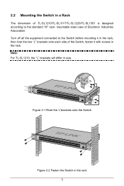
Turn off all the equipment connected to the standard 19'' rack- Note: For TL-SL1210, the "L" brackets will differ in the rack 3 Figure 2-1 Rivet the 'L'brackets onto the Switch Figure 2-2 Fasten the Switch in size. 2.2 Mounting the Switch in a Rack The dimension of TL-SL1210/TL-SL1117/TL-SL1226/TL-SL1351 is designed according to the Switch before mounting it in the rack, then rivet the two "L" brackets onto each side of Electronic Industries Association. mountable steel case of the Switch, fasten it with screws in the rack.
Turn off all the equipment connected to the standard 19'' rack- Note: For TL-SL1210, the "L" brackets will differ in the rack 3 Figure 2-1 Rivet the 'L'brackets onto the Switch Figure 2-2 Fasten the Switch in size. 2.2 Mounting the Switch in a Rack The dimension of TL-SL1210/TL-SL1117/TL-SL1226/TL-SL1351 is designed according to the Switch before mounting it in the rack, then rivet the two "L" brackets onto each side of Electronic Industries Association. mountable steel case of the Switch, fasten it with screws in the rack.
TL-SL1117 V2 QIG 7106503252
Page 8
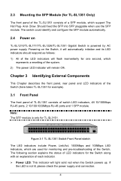
... Panel sketch The LED indicators include Power, Link/Act, 1000Mbps and 100Mbps LED indicators, which represents a resetting of the system. 2) The power LED indicator will remain ON. Draw. Powering on TL-SL1210/TL-SL1117/TL-SL1226/TL-SL1351 Gigabit Switch is not lit, please check the power supply and connection. 4 Chapter 3 Identifying External Components This Chapter describes...
... Panel sketch The LED indicators include Power, Link/Act, 1000Mbps and 100Mbps LED indicators, which represents a resetting of the system. 2) The power LED indicator will remain ON. Draw. Powering on TL-SL1210/TL-SL1117/TL-SL1226/TL-SL1351 Gigabit Switch is not lit, please check the power supply and connection. 4 Chapter 3 Identifying External Components This Chapter describes...

TL-SL1117 V2 QIG 7106503252
Page 9
.... 3.2 Rear Panel The rear panel of the power cord head here, and the male head to a 1000Mbps device. Connect the female of the TL-SL1351 features a power receptacle, which is connected correctly. It flashes green when data is being transmitted or received on the working connection. ¾...when the corresponding port is an AC power receptacle. It flashes green when data is being transmitted or received on the working connection. ¾ Link/Act LED: This indicator will light solid green when the 10/100M port connected to a 100Mbps device. ¾ 1000M LED: The corresponding ...
.... 3.2 Rear Panel The rear panel of the power cord head here, and the male head to a 1000Mbps device. Connect the female of the TL-SL1351 features a power receptacle, which is connected correctly. It flashes green when data is being transmitted or received on the working connection. ¾...when the corresponding port is an AC power receptacle. It flashes green when data is being transmitted or received on the working connection. ¾ Link/Act LED: This indicator will light solid green when the 10/100M port connected to a 100Mbps device. ¾ 1000M LED: The corresponding ...

