
User Manual
Page 2
... Conformity Trade Name: SONY Model: VPL-EW5, VPL-EX50,VPLEX5, VPL-ES5 Responsible Party: Sony Electronics Inc. WARNING When installing the unit, incorporate a readily accessible disconnect device in USA, use the UL LISTED power cord specified below. If you may cause undesired operation. If used batteries according to qualified personnel only. Dispose of used in the fixed wiring, or connect the power plug to operate this equipment. For...
... Conformity Trade Name: SONY Model: VPL-EW5, VPL-EX50,VPLEX5, VPL-ES5 Responsible Party: Sony Electronics Inc. WARNING When installing the unit, incorporate a readily accessible disconnect device in USA, use the UL LISTED power cord specified below. If you may cause undesired operation. If used batteries according to qualified personnel only. Dispose of used in the fixed wiring, or connect the power plug to operate this equipment. For...
User Manual
Page 4
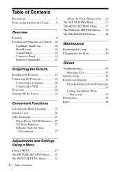
... Tools for Your Presentation 27 About the Preset Memory No. ....34 The SET SETTING Menu 35 The MENU SETTING Menu ...........37 The INSTALL SETTING Menu .......38 The INFORMATION Menu 40 Maintenance Replacing the Lamp 42 Cleaning the Air Filter 44 Others Troubleshooting 45 Messages List 47 Specifications 49 Installation Diagram 54 Floor Installation (Front Projection 54 Ceiling Installation (Front Projection 56 Dimensions 58 Index 60 Adjustments and Settings Using a Menu Using a MENU 29 The PICTURE SETTING Menu ...... 31 The INPUT SETTING Menu .......... 33 4 Table of Contents
... Tools for Your Presentation 27 About the Preset Memory No. ....34 The SET SETTING Menu 35 The MENU SETTING Menu ...........37 The INSTALL SETTING Menu .......38 The INFORMATION Menu 40 Maintenance Replacing the Lamp 42 Cleaning the Air Filter 44 Others Troubleshooting 45 Messages List 47 Specifications 49 Installation Diagram 54 Floor Installation (Front Projection 54 Ceiling Installation (Front Projection 56 Dimensions 58 Index 60 Adjustments and Settings Using a Menu Using a MENU 29 The PICTURE SETTING Menu ...... 31 The INPUT SETTING Menu .......... 33 4 Table of Contents
User Manual
Page 5
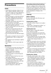
...; Check that the operating voltage of your unit is not to be used for the air filter cleaning. If voltage adaptation is required, consult with qualified Sony personnel. • Should any windows that face the screen with a soft dry cloth. • Use of alcohol, benzene, thinner or insecticide may be exposed to direct lighting or sunlight. • Ceiling-mounted spot lighting is equipped with respect to install...
...; Check that the operating voltage of your unit is not to be used for the air filter cleaning. If voltage adaptation is required, consult with qualified Sony personnel. • Should any windows that face the screen with a soft dry cloth. • Use of alcohol, benzene, thinner or insecticide may be exposed to direct lighting or sunlight. • Ceiling-mounted spot lighting is equipped with respect to install...
User Manual
Page 9
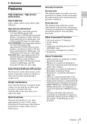
... the Video Electronics Standards Association. • Display Data Channel is located at the same time as you can be turned on the ceiling, you replace the lamp. VPL-EX50/EX5:Three super-high-aperture 0.63-inch XGA panels with approximately 1,020,000 effective pixels produce a resolution of 1280 × 800 dots (horizontal/vertical) for RGB input, and 750 horizontal TV lines for the entire system can clean the air filter...
... the Video Electronics Standards Association. • Display Data Channel is located at the same time as you can be turned on the ceiling, you replace the lamp. VPL-EX50/EX5:Three super-high-aperture 0.63-inch XGA panels with approximately 1,020,000 effective pixels produce a resolution of 1280 × 800 dots (horizontal/vertical) for RGB input, and 750 horizontal TV lines for the entire system can clean the air filter...

User Manual
Page 12
Flashes in the menu system, select a menu, or make various adjustments. Flashes in orange under the following conditions: • A reception rate of its life or reaches a high temperature. b INPUT key Selects an input signal. d LAMP/COVER indicators Flashes in green from the projector is turned on until the projector is not secured firmly. • A reception rate of 3 flashes when the lamp has reached the end of 2 flashes when the lamp cover or air filter cover is ready to operate. Once...
Flashes in the menu system, select a menu, or make various adjustments. Flashes in orange under the following conditions: • A reception rate of its life or reaches a high temperature. b INPUT key Selects an input signal. d LAMP/COVER indicators Flashes in green from the projector is turned on until the projector is not secured firmly. • A reception rate of 3 flashes when the lamp has reached the end of 2 flashes when the lamp cover or air filter cover is ready to operate. Once...
User Manual
Page 15
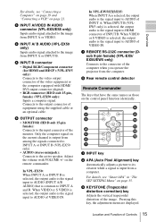
... signal input to AUDIO of equipment using the supplied cable or an optional cable. Location and Function of INPUT B. d INPUT A/ B AUDIO (VPL-EX50 only) Inputs audio signal attached to AUDIO of VIDEO IN. on page 21. When INPUT B (VPLEW5 only) is selected, the output audio is common to the input connector of the image. c KEYSTONE (Trapezoidal distortion correction) key Adjusts the vertical trapezoidal distortion of the monitor. c INPUT A/VIDEO IN AUDIO connector (VPL-EX5/ES5 only) Inputs audio signal attached to HDMI...
... signal input to AUDIO of equipment using the supplied cable or an optional cable. Location and Function of INPUT B. d INPUT A/ B AUDIO (VPL-EX50 only) Inputs audio signal attached to AUDIO of VIDEO IN. on page 21. When INPUT B (VPLEW5 only) is selected, the output audio is common to the input connector of the image. c KEYSTONE (Trapezoidal distortion correction) key Adjusts the vertical trapezoidal distortion of the monitor. c INPUT A/VIDEO IN AUDIO connector (VPL-EX5/ES5 only) Inputs audio signal attached to HDMI...
User Manual
Page 21
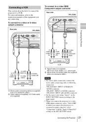
... supplied) (Use a no-resistance cable.) Notes • For stereo audio connection, connect the stereo audio connecting cable to a component output connector, select "Component" with the "Input-A Signal Sel." For more information, refer to a VCR. Connecting the Projector 21 Connecting a VCR This section describes how to connect the projector to the instruction manuals of the equipment you connect the projector to following connectors: VPL-EX5/ES5: INPUT A/VIDEO IN AUDIO connector VPL-EW5: INPUT A AUDIO connector VPL-EX50: INPUT A/B AUDIO connector • Set...
... supplied) (Use a no-resistance cable.) Notes • For stereo audio connection, connect the stereo audio connecting cable to a component output connector, select "Component" with the "Input-A Signal Sel." For more information, refer to a VCR. Connecting the Projector 21 Connecting a VCR This section describes how to connect the projector to the instruction manuals of the equipment you connect the projector to following connectors: VPL-EX5/ES5: INPUT A/VIDEO IN AUDIO connector VPL-EW5: INPUT A AUDIO connector VPL-EX50: INPUT A/B AUDIO connector • Set...
User Manual
Page 22
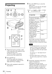
... the input source. Projecting 1,2 4 Press the INPUT key to the S VIDEO input connector S-Video Smart APA (Auto Pixel Alignment) adjusts the picture of your computer, for example a notebook, or an all equipment, then remove the lens cover. Notes • If "Auto Input Search" is effective for the input analog signal from the connected equipment and displays the input channel where the input signals are found. The ?/1 key lights after flashing in green. (The projector cannot be used...
... the input source. Projecting 1,2 4 Press the INPUT key to the S VIDEO input connector S-Video Smart APA (Auto Pixel Alignment) adjusts the picture of your computer, for example a notebook, or an all equipment, then remove the lens cover. Notes • If "Auto Input Search" is effective for the input analog signal from the connected equipment and displays the input channel where the input signals are found. The ?/1 key lights after flashing in green. (The projector cannot be used...
User Manual
Page 29
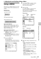
... the MENU key. Use the v or V key to select a menu, then press the B or ENTER key. For Video/S-Video input: Shows "Auto" or the "Color System" setting on -screen menu for making various adjustments and settings. The menu appears. Press the ENTER or b key to change the setting. SET SETTING Input-A Smar t APA: On Auto Input Search: Off Input-A Signal Sel.: Component Color System: Auto Power Saving: Off IR Receiver: Front & Rear Panel Key Lock: Off Lamp Timer Reset Sub menu Menu Setting items PICTURE SETTING Input A ADJUST PICTURE...
... the MENU key. Use the v or V key to select a menu, then press the B or ENTER key. For Video/S-Video input: Shows "Auto" or the "Color System" setting on -screen menu for making various adjustments and settings. The menu appears. Press the ENTER or b key to change the setting. SET SETTING Input-A Smar t APA: On Auto Input Search: Off Input-A Signal Sel.: Component Color System: Auto Power Saving: Off IR Receiver: Front & Rear Panel Key Lock: Off Lamp Timer Reset Sub menu Menu Setting items PICTURE SETTING Input A ADJUST PICTURE...
User Manual
Page 34
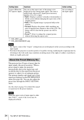
... the "Aspect" setting items are displayed on the screen according to the input signal. • Note that if the projector is used for profit or for the signal from the preset memory to adjust it to enlarge the original picture without changing the aspect ratio of the original picture. • Full 2: The original image is projected fully in the window. • Normal: Displays the picture while matching...
... the "Aspect" setting items are displayed on the screen according to the input signal. • Note that if the projector is used for profit or for the signal from the preset memory to adjust it to enlarge the original picture without changing the aspect ratio of the original picture. • Full 2: The original image is projected fully in the window. • Normal: Displays the picture while matching...
User Manual
Page 36
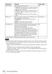
When replacing the lamps, reset the lamp timer. - To use it is in standby mode, and turns the projector to "Off." Notes • Press the APA key when the full image is automatically set to standby mode when the power is input for 10 minutes. If you adjust the picture manually. • If the input signal is not displayed correctly when the input A signal classifying is input for 10 minutes. If the projected image includes a black portion around...
When replacing the lamps, reset the lamp timer. - To use it is in standby mode, and turns the projector to "Off." Notes • Press the APA key when the full image is automatically set to standby mode when the power is input for 10 minutes. If you adjust the picture manually. • If the input signal is not displayed correctly when the input A signal classifying is input for 10 minutes. If the projected image includes a black portion around...
User Manual
Page 38
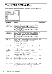
... turn the power on the projector. 38 The INSTALL SETTING Menu Select "Auto" for automatic correction, or "Manual" for changing the settings of the screen when no signal Blue is longer than the top : Sets a lower value. Background Selects the background color of the projector. When the bottom of the projected image will be lower compared with the "High" setting. INSTALL SETTING V Keystone: Auto Image Flip: Off Background: Blue Lamp Mode: Standard High Altitude Mode:Off Security Lock: Off Direct Power On: Off Input-A Setting...
... turn the power on the projector. 38 The INSTALL SETTING Menu Select "Auto" for automatic correction, or "Manual" for changing the settings of the screen when no signal Blue is longer than the top : Sets a lower value. Background Selects the background color of the projector. When the bottom of the projected image will be lower compared with the "High" setting. INSTALL SETTING V Keystone: Auto Image Flip: Off Background: Blue Lamp Mode: Standard High Altitude Mode:Off Security Lock: Off Direct Power On: Off Input-A Setting...
User Manual
Page 42
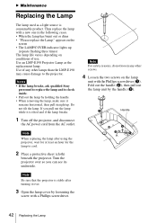
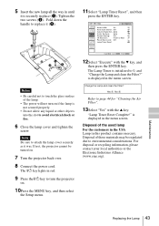
... the lamp. Turn the projector over . 3 Open the lamp cover by the handle (c). Fold out the handle (b), then pull out the lamp unit by loosening the screw with a Phillips screwdriver. B Maintenance Replacing the Lamp The lamp used as the replacement lamp. Use of use. Note When replacing the lamp after turning it over so you pull out the lamp while it remains horizontal, then pull straight up (repeats flashing three times) The lamp life...
... the lamp. Turn the projector over . 3 Open the lamp cover by the handle (c). Fold out the handle (b), then pull out the lamp unit by loosening the screw with a Phillips screwdriver. B Maintenance Replacing the Lamp The lamp used as the replacement lamp. Use of use. Note When replacing the lamp after turning it over so you pull out the lamp while it remains horizontal, then pull straight up (repeats flashing three times) The lamp life...
User Manual
Page 43
... the Setup menu. 12Select "Execute" with the v key. SET SETTING Input-A Smar t APA: On Auto Input Search: Off Input-A Signal Sel.: Auto Color System: Auto Power Saving: Off IR Receiver: Front & Rear Panel Key Lock: Off Lamp Timer Reset Notes • Be careful not to replace it was. The ?/1 key lights in red. 9 Press the ?/1 key to avoid electrical shock or fire. 6 Close the lamp cover and tighten the screw. Change the Lamp and clean the Filter? Disposal...
... the Setup menu. 12Select "Execute" with the v key. SET SETTING Input-A Smar t APA: On Auto Input Search: Off Input-A Signal Sel.: Auto Color System: Auto Power Saving: Off IR Receiver: Front & Rear Panel Key Lock: Off Lamp Timer Reset Notes • Be careful not to replace it was. The ?/1 key lights in red. 9 Press the ?/1 key to avoid electrical shock or fire. 6 Close the lamp cover and tighten the screw. Change the Lamp and clean the Filter? Disposal...
User Manual
Page 45
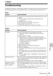
... combination of the number of a computer. Noise may appear on the background depending on the LCD panel. The input signal cannot be operating erratically, try to diagnose and correct the problem using the following procedures. 1 Connect the projector to the computer. 2 Turn the projector on with qualified Sony personnel. c Select the input source correctly (see page 43). • The air filter cover is muted. c Close the lamp cover securely (see...
... combination of the number of a computer. Noise may appear on the background depending on the LCD panel. The input signal cannot be operating erratically, try to diagnose and correct the problem using the following procedures. 1 Connect the projector to the computer. 2 Turn the projector on with qualified Sony personnel. c Select the input source correctly (see page 43). • The air filter cover is muted. c Close the lamp cover securely (see...
User Manual
Page 46
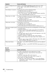
.... c Replace the lamp with a new one (see page 33). • This input signal cannot be projected as the frequency is dim. c Display the full image on the INPUT SETTING menu has not been adjusted properly. Sound Symptom No sound. Color balance is not adjusted properly. c Set "Color System" on the lens. c Adjust "Shift" on the PICTURE SETTING menu (see page 33). c Input a signal that the proper connections have been made (see page 19). "Dot Phase" on the screen...
.... c Replace the lamp with a new one (see page 33). • This input signal cannot be projected as the frequency is dim. c Display the full image on the INPUT SETTING menu has not been adjusted properly. Sound Symptom No sound. Color balance is not adjusted properly. c Set "Color System" on the lens. c Adjust "Shift" on the PICTURE SETTING menu (see page 33). c Input a signal that the proper connections have been made (see page 19). "Dot Phase" on the screen...
User Manual
Page 47
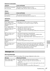
... Remote Commander The Remote Commander battery are locked. Cause and Remedy The control panel keys are dead. c Attach the cover securely (see that "High Altitude Mode" in the Setup menu is being used at a high altitude. Others Messages List Warning Messages Use the list below to cool the lamp and then turn the projector on the screen. indicator flashes in red and the problem persists, the electrical system has failed. c Perform the operation of 2 flashes) • The internal temperature...
... Remote Commander The Remote Commander battery are locked. Cause and Remedy The control panel keys are dead. c Attach the cover securely (see that "High Altitude Mode" in the Setup menu is being used at a high altitude. Others Messages List Warning Messages Use the list below to cool the lamp and then turn the projector on the screen. indicator flashes in red and the problem persists, the electrical system has failed. c Perform the operation of 2 flashes) • The internal temperature...

User Manual
Page 49
...-inch XGA panel, about 2,360,000 pixels (1024 × 768 × 3) VPL-EW5: 0.59-inchvWXGA panel, about 3,070,000 pixels (1280 × 800 × 3) Lens 1.2 times zoom lens f 18.53 to 22.18 mm/F1.65 to 1.93 Lamp 190 W Ultra high pressure lamp Projected picture size 40 to 300 inches (measured diagonally) Light output VPL-EX501): 2500 lm VPL-EW51)/EX5/ES5: 2000 lm 1) When the Lamp Mode is set...
...-inch XGA panel, about 2,360,000 pixels (1024 × 768 × 3) VPL-EW5: 0.59-inchvWXGA panel, about 3,070,000 pixels (1280 × 800 × 3) Lens 1.2 times zoom lens f 18.53 to 22.18 mm/F1.65 to 1.93 Lamp 190 W Ultra high pressure lamp Projected picture size 40 to 300 inches (measured diagonally) Light output VPL-EX501): 2500 lm VPL-EW51)/EX5/ES5: 2000 lm 1) When the Lamp Mode is set...

User Manual
Page 51
...GND (B) RS-232C connector (D-sub 9 pin, female) (VPL-EW5/EX50/EX5 only) 1 R/R-Y 9 Power supply input for replacement) Some of the items may not be available in some areas. Note Always verify that the unit is operating properly before use. SONY WILL NOT BE LIABLE FOR DAMAGES OF ANY KIND INCLUDING, ... WHATSOEVER. Optional accessories Projector Lamp LMP-E190(for DDC 2 G/Y 10 GND 3 B/B-Y 11 GND 4 RESERVE 12 DDC/SDA 5 GND 13 HD 6 GND (R) 14 VD 7 GND (G) 15 DDC/SCL 8 GND (B) 1 NC 2 RXDA 3 TXDA 4 DTR 5 GND 6 NC 7 RTS 8 CTS 9 NC Others Specifications 51
...GND (B) RS-232C connector (D-sub 9 pin, female) (VPL-EW5/EX50/EX5 only) 1 R/R-Y 9 Power supply input for replacement) Some of the items may not be available in some areas. Note Always verify that the unit is operating properly before use. SONY WILL NOT BE LIABLE FOR DAMAGES OF ANY KIND INCLUDING, ... WHATSOEVER. Optional accessories Projector Lamp LMP-E190(for DDC 2 G/Y 10 GND 3 B/B-Y 11 GND 4 RESERVE 12 DDC/SDA 5 GND 13 HD 6 GND (R) 14 VD 7 GND (G) 15 DDC/SCL 8 GND (B) 1 NC 2 RXDA 3 TXDA 4 DTR 5 GND 6 NC 7 RTS 8 CTS 9 NC Others Specifications 51
User Manual
Page 60
... Lamp Timer 40 Lamp Timer Reset 36 Language 37 selecting the menu language 25 Lens 11 Location and function of controls connector panel 14 control panel 12 rear/bottom 10 Remote Commander 15 top/right side/front 10 M Menu clearing the menu display 30 INFORMATION Menu 40 INPUT SETTING menu 33 INSTALL SETTING menu 38 MENU SETTING menu 37 PICTURE SETTING menu 31 SET SETTING menu 35 using a menu 29 Menu Position 37 Message List caution 48 warning 47 O Optional accessories 51 P Panel Key Lock 36 Picture Mode 31 Pin assignment 51 Power turn...
... Lamp Timer 40 Lamp Timer Reset 36 Language 37 selecting the menu language 25 Lens 11 Location and function of controls connector panel 14 control panel 12 rear/bottom 10 Remote Commander 15 top/right side/front 10 M Menu clearing the menu display 30 INFORMATION Menu 40 INPUT SETTING menu 33 INSTALL SETTING menu 38 MENU SETTING menu 37 PICTURE SETTING menu 31 SET SETTING menu 35 using a menu 29 Menu Position 37 Message List caution 48 warning 47 O Optional accessories 51 P Panel Key Lock 36 Picture Mode 31 Pin assignment 51 Power turn...


