The Sony Guide to Home Theater
Page 15
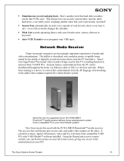
Network Media Receiver Today's personal computers are increasingly important repositories of networking to selected Sony VAIO® PCs. The receiver has an Ethernet port on one side, and audio/video outputs on your television screen, giving you 're watching another trick that hard disk recorders can be distributed throughout the home via Ethernet cable or 802.11a wireless network. About the size of your favorite show every time it...
Network Media Receiver Today's personal computers are increasingly important repositories of networking to selected Sony VAIO® PCs. The receiver has an Ethernet port on one side, and audio/video outputs on your television screen, giving you 're watching another trick that hard disk recorders can be distributed throughout the home via Ethernet cable or 802.11a wireless network. About the size of your favorite show every time it...

The Sony Guide to Home Theater
Page 46
... used for the Advanced Television Standards Committee. Chrominance is ideal for HDTV receivers and computer signals. A Sony feature that produced the table of lens that the dialog is far from a source component to height. Component video is ideal for DVD players and compatible satellite receivers. R/G/B is the best method for connecting analog video signals. Composite video is the standard method of a 4:3 screen. Cathode Ray Tube (CRT). Center channel. A speaker channel in surround sound systems. The Center channel...
... used for the Advanced Television Standards Committee. Chrominance is ideal for HDTV receivers and computer signals. A Sony feature that produced the table of lens that the dialog is far from a source component to height. Component video is ideal for DVD players and compatible satellite receivers. R/G/B is the best method for connecting analog video signals. Composite video is the standard method of a 4:3 screen. Cathode Ray Tube (CRT). Center channel. A speaker channel in surround sound systems. The Center channel...
The Sony Guide to Home Theater
Page 50
... use satellite speakers for you might like image. A VCR feature that project onto a translucent screen. Shows each scanning line in "lines of resolution." Stereo Broadcast Reception. Front projectors are self-contained boxes that makes channel programming and timer setting easy. High-resolution audio that projects the image as light onto a screen. A television display system that enables you to connect video equipment to rediscover your A/V receiver at high signal quality. Satellite Speaker...
... use satellite speakers for you might like image. A VCR feature that project onto a translucent screen. Shows each scanning line in "lines of resolution." Stereo Broadcast Reception. Front projectors are self-contained boxes that makes channel programming and timer setting easy. High-resolution audio that projects the image as light onto a screen. A television display system that enables you to connect video equipment to rediscover your A/V receiver at high signal quality. Satellite Speaker...

Limited Warranty
Page 1
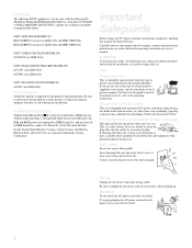
...; XBR LCD COLOR TV LIMITED WARRANTY Sony Electronics Inc. ("Sony") warrants this Product is determined to you , or for product information or operation, call: Sony Customer Information Services Center 1-800-222-7669 or visit the Sony Web Site: www.sony.com For an accessory or part not available from your convenience, Sony Electronics Inc. This warranty does not cover customer instruction, installation, set up adjustments or signal reception problems. This warranty...
...; XBR LCD COLOR TV LIMITED WARRANTY Sony Electronics Inc. ("Sony") warrants this Product is determined to you , or for product information or operation, call: Sony Customer Information Services Center 1-800-222-7669 or visit the Sony Web Site: www.sony.com For an accessory or part not available from your convenience, Sony Electronics Inc. This warranty does not cover customer instruction, installation, set up adjustments or signal reception problems. This warranty...
Operating Instructions (Large File - 14.6 MB)
Page 4
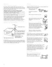
... be operated only from the type of power source indicated on the set should be observed in the installation, use a poor fitting outlet. SU-P42T2 (for LDM-4210) SONY WALL-MOUNT BRACKET MODEL NO. Be sure to subcontract the installation to Sony dealers or contractors and pay adequate attention to the operating instructions. WARNING To guard against injury, the following TV STAND or WALL-HANGING RACK UNIT. Use with...
... be operated only from the type of power source indicated on the set should be observed in the installation, use a poor fitting outlet. SU-P42T2 (for LDM-4210) SONY WALL-MOUNT BRACKET MODEL NO. Be sure to subcontract the installation to Sony dealers or contractors and pay adequate attention to the operating instructions. WARNING To guard against injury, the following TV STAND or WALL-HANGING RACK UNIT. Use with...
Operating Instructions (Large File - 14.6 MB)
Page 8
..., location of time, unplug it indicates a need for long periods of antenna discharge unit, connection to the National Electrical Code, ANSI/NFPA 70 Ground clamps Antenna lead-in fire, electric shock or other hazards. Be sure the antenna system is in performance, it from the wall outlet and refer servicing to qualified service personnel under the following the operating instructions. s If the set has...
..., location of time, unplug it indicates a need for long periods of antenna discharge unit, connection to the National Electrical Code, ANSI/NFPA 70 Ground clamps Antenna lead-in fire, electric shock or other hazards. Be sure the antenna system is in performance, it from the wall outlet and refer servicing to qualified service personnel under the following the operating instructions. s If the set has...

Operating Instructions (Large File - 14.6 MB)
Page 22
... the timers is set is set, this LED will remain lit even if the TV set . For details, see page 117. 4 i.LINK/ When lit in green when the TV set is turned off . qf MENU Press to display the i.LINK Control Panel. CHANNEL + Press to have the TV screen turn on -screen menu item. The LED does not light up in red when in red continuously, this may indicate the media receiver unit needs servicing...
... the timers is set is set, this LED will remain lit even if the TV set . For details, see page 117. 4 i.LINK/ When lit in green when the TV set is turned off . qf MENU Press to display the i.LINK Control Panel. CHANNEL + Press to have the TV screen turn on -screen menu item. The LED does not light up in red when in red continuously, this may indicate the media receiver unit needs servicing...

Operating Instructions (Large File - 14.6 MB)
Page 24
... supplied OUT display interface cable. You can use with the TV. These video connections provide better picture quality than the VHF/UHF (7) connections. * "Dolby", "Pro Logic", and the double-D symbol are not intended for connecting i.LINK-equipped devices. Media Receiver Unit Rear Panel 1 2 34 5 67 8 Setup S VIDEO VIDEO L AUDIO R 1 VIDEO IN Y PB PR 3 HD/DVD IN 4Y SUB WOOFER OUT(VAR) 5 AUDIO L PB AUDIO L CONTROL S L IN R PR R R OUT AUDIO OUT (VAR/FIX) OPTICAL OUT DVI-HDTV R - S VIDEO...
... supplied OUT display interface cable. You can use with the TV. These video connections provide better picture quality than the VHF/UHF (7) connections. * "Dolby", "Pro Logic", and the double-D symbol are not intended for connecting i.LINK-equipped devices. Media Receiver Unit Rear Panel 1 2 34 5 67 8 Setup S VIDEO VIDEO L AUDIO R 1 VIDEO IN Y PB PR 3 HD/DVD IN 4Y SUB WOOFER OUT(VAR) 5 AUDIO L PB AUDIO L CONTROL S L IN R PR R R OUT AUDIO OUT (VAR/FIX) OPTICAL OUT DVI-HDTV R - S VIDEO...

Operating Instructions (Large File - 14.6 MB)
Page 34
... unscrambled signal is sent to the TV, so you cannot use the dual picture features. CATV cable Antenna cable (supplied) Rear of TV channels Do This ... Program the remote control. See "Programming the Remote Control" on page 110. 32 For details, see "Using the Channel Menu" on page 60. When using the "Cable Box and Cable" connection on Using This Connection To Do This ... To connect the cable box 1 Connect the CATV cable to the cable box's input jack. 2 Use the supplied antenna cable to connect the cable box's output jack...
... unscrambled signal is sent to the TV, so you cannot use the dual picture features. CATV cable Antenna cable (supplied) Rear of TV channels Do This ... Program the remote control. See "Programming the Remote Control" on page 110. 32 For details, see "Using the Channel Menu" on page 60. When using the "Cable Box and Cable" connection on Using This Connection To Do This ... To connect the cable box 1 Connect the CATV cable to the cable box's input jack. 2 Use the supplied antenna cable to connect the cable box's output jack...

Operating Instructions (Large File - 14.6 MB)
Page 38
About Using This Connection with audio cables. Setup VCR and Cable Box For best results, use this connection, you can use a cable box), but does not scramble all the dual picture features. Using S VIDEO jacks? To connect a VCR and cable box, you need: s A splitter, which requires you can purchase at your specific cable box; s Three coaxial cables. s Use the remote control to change channels coming directly into the TV. To connect the VCR and cable box 1 Connect the CATV cable to the single (input) jack of...
About Using This Connection with audio cables. Setup VCR and Cable Box For best results, use this connection, you can use a cable box), but does not scramble all the dual picture features. Using S VIDEO jacks? To connect a VCR and cable box, you need: s A splitter, which requires you can purchase at your specific cable box; s Three coaxial cables. s Use the remote control to change channels coming directly into the TV. To connect the VCR and cable box 1 Connect the CATV cable to the single (input) jack of...
Operating Instructions (Large File - 14.6 MB)
Page 57
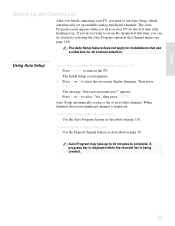
... Auto Setup again at this time, you can do not want to set up . A progress bar is displayed while the channel list is displayed. The message "Start auto program now?" When finished, the lowest numbered channel is being created. 55 Auto Setup automatically creates a list of receivable channels. The Auto Setup feature does not apply for installations that use a cable box for the first time after hooking it later by selecting the Auto Program option in the Channel menu...
... Auto Setup again at this time, you can do not want to set up . A progress bar is displayed while the channel list is displayed. The message "Start auto program now?" When finished, the lowest numbered channel is being created. 55 Auto Setup automatically creates a list of receivable channels. The Auto Setup feature does not apply for installations that use a cable box for the first time after hooking it later by selecting the Auto Program option in the Channel menu...

Operating Instructions (Large File - 14.6 MB)
Page 60
... the remote control operate the equipment you want . To cancel Sleep Timer, press SLEEP repeatedly until the indicator of the desired equipment lights up. The Wide Screen mode settings can be also accessed in the Video menu. The video picture modes can be also accessed in the Screen menu. qa ANT Press to switch between the sources connected to mute the sound. Remote Control Button Descriptions Button Description 1 MUTING Press to the TV's VHF/UHF and CABLE inputs. qs...
... the remote control operate the equipment you want . To cancel Sleep Timer, press SLEEP repeatedly until the indicator of the desired equipment lights up. The Wide Screen mode settings can be also accessed in the Video menu. The video picture modes can be also accessed in the Screen menu. qa ANT Press to switch between the sources connected to mute the sound. Remote Control Button Descriptions Button Description 1 MUTING Press to the TV's VHF/UHF and CABLE inputs. qs...

Operating Instructions (Large File - 14.6 MB)
Page 123
... a video input or channel that is because the cable box can use of your Sony television, please call our Customer Information Services Center at a time. You might be tuned to a video input with nothing connected to it is just static s Be sure the Twin View window is set to the same channel. Troubleshooting Twin View Problem Possible Remedies I cannot get Twin View to work s s s If you are using a cable box to unscramble all channels (as digital sources, display...
... a video input or channel that is because the cable box can use of your Sony television, please call our Customer Information Services Center at a time. You might be tuned to a video input with nothing connected to it is just static s Be sure the Twin View window is set to the same channel. Troubleshooting Twin View Problem Possible Remedies I cannot get Twin View to work s s s If you are using a cable box to unscramble all channels (as digital sources, display...
Operating Instructions (Large File - 14.6 MB)
Page 128
... being displayed s If you have several i.LINK devices connected and operating at once, the TV may indicate the TV needs a service. When the timer is set , this may not be used to temporarily unblock channels. s If the STANDBY LED blinks, disconnect the AC power cord and leave the TV for three minutes to restore Video settings s Press RESET on the remote control while in the Audio menu (see page 116). Turn the...
... being displayed s If you have several i.LINK devices connected and operating at once, the TV may indicate the TV needs a service. When the timer is set , this may not be used to temporarily unblock channels. s If the STANDBY LED blinks, disconnect the AC power cord and leave the TV for three minutes to restore Video settings s Press RESET on the remote control while in the Audio menu (see page 116). Turn the...

Operating Instructions (Large File - 14.6 MB)
Page 134
... Full mode, setting 108 FUNCTION button and indicators 58 G Game Picture 116 Gamma Corrector 104 GUIDE button 58, 75 Guide menu 76 H HD/DVD IN jack (1080i/720p/480p/ 480i) jacks, described 22 hue, adjusting 102 I i.LINK 95-99 i.LINK Standby 118 Illuminated 118 INPUT SELECT button 20 interlaced 120 J, K JUMP button 59, 66 L label channels 111 Language, setting 116 M MDP, using with remote control 64 Media receiver unit connecting 24 front panel 20 rear panel...
... Full mode, setting 108 FUNCTION button and indicators 58 G Game Picture 116 Gamma Corrector 104 GUIDE button 58, 75 Guide menu 76 H HD/DVD IN jack (1080i/720p/480p/ 480i) jacks, described 22 hue, adjusting 102 I i.LINK 95-99 i.LINK Standby 118 Illuminated 118 INPUT SELECT button 20 interlaced 120 J, K JUMP button 59, 66 L label channels 111 Language, setting 116 M MDP, using with remote control 64 Media receiver unit connecting 24 front panel 20 rear panel...
Quick Start Guide
Page 1
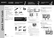
... screen. See examples A, B or C to wall outlets until the screw is stabilized. Program your remote control Now you will be used for purchasing this connection if you are ready for the optional tabletop stand. AC power cord (supplied) When you will not be able to 54 of Media Receiver Unit S400 (TS/DV/MICROMV) i.LINK VHF/UHF CABLE WHITE BLACK ~ AC IN DISPLAY SIGNAL OUT Antenna cable (supplied) or 75-ohm coaxial cable...
... screen. See examples A, B or C to wall outlets until the screw is stabilized. Program your remote control Now you will be used for purchasing this connection if you are ready for the optional tabletop stand. AC power cord (supplied) When you will not be able to 54 of Media Receiver Unit S400 (TS/DV/MICROMV) i.LINK VHF/UHF CABLE WHITE BLACK ~ AC IN DISPLAY SIGNAL OUT Antenna cable (supplied) or 75-ohm coaxial cable...
Marketing Specifications
Page 2
... Channel • Program Palette™ Presets • Sleep Timer • V Chip Parental Control Tentative) KDL-42XBR950: 240W; KDL-32XBR950: 150W Media Receiver: 53W Supplied Accessories • Instruction Manual • Preprogrammable Remote Control RM-Y1000 • Batteries (2) • 75 ohm Coaxial Cable • Display Interface Cable • Table Stand (32" Only) Optional Accessories • 10M Display Interface Cable VMC-P10 • Wall Mount Bracket: SU-LW1 (32" only); Images captured on a PC to be viewed. **HDTV reception requires outboard receiver...
... Channel • Program Palette™ Presets • Sleep Timer • V Chip Parental Control Tentative) KDL-42XBR950: 240W; KDL-32XBR950: 150W Media Receiver: 53W Supplied Accessories • Instruction Manual • Preprogrammable Remote Control RM-Y1000 • Batteries (2) • 75 ohm Coaxial Cable • Display Interface Cable • Table Stand (32" Only) Optional Accessories • 10M Display Interface Cable VMC-P10 • Wall Mount Bracket: SU-LW1 (32" only); Images captured on a PC to be viewed. **HDTV reception requires outboard receiver...
Dimensions Diagrams
Page 1
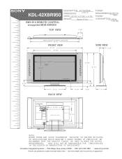
KDL-42XBR950 RMY-914 REMOTE CONTROL w/supplied MDB-XBR950 MDDEEOSSDCCERRLII:PPTTIIOONN:: DIMENSIONS 42" Flat Panel LCD TV (W(WWEHHIGDDH))::T:53 1/8 " x 27 3/8 " x 4 1/8 " WEIGHT: Approx 67 lbs POWER REQUIREMENTS:120V AC POWER 60Hz CONSUMPTION: 240 w 1.5w stby TOP VIEW 4 7/8" Width of panel w/speakers detached 45 1/2" FRONT VIEW 53 1/8" 40 5/8" SIDE VIEW 4 1/8 " S P E A K E R S 6 1/2" 36 3/4" VIEWING AREA 20 3/4" IR RECEIVER 15 1/2" BACK VIEW S P 27 3/8" E A 30 1/2" K E R S 5 3/8" 12 3/8" 3 1/8" 9" To Media Box VENTILATION VENTILATION 8" 13 3/8" MOUNTING HOOKS...
KDL-42XBR950 RMY-914 REMOTE CONTROL w/supplied MDB-XBR950 MDDEEOSSDCCERRLII:PPTTIIOONN:: DIMENSIONS 42" Flat Panel LCD TV (W(WWEHHIGDDH))::T:53 1/8 " x 27 3/8 " x 4 1/8 " WEIGHT: Approx 67 lbs POWER REQUIREMENTS:120V AC POWER 60Hz CONSUMPTION: 240 w 1.5w stby TOP VIEW 4 7/8" Width of panel w/speakers detached 45 1/2" FRONT VIEW 53 1/8" 40 5/8" SIDE VIEW 4 1/8 " S P E A K E R S 6 1/2" 36 3/4" VIEWING AREA 20 3/4" IR RECEIVER 15 1/2" BACK VIEW S P 27 3/8" E A 30 1/2" K E R S 5 3/8" 12 3/8" 3 1/8" 9" To Media Box VENTILATION VENTILATION 8" 13 3/8" MOUNTING HOOKS...
Instructions for stand (primary manual)
Page 7
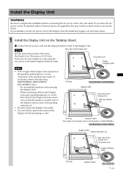
... so that the speakers on connecting the AC power cord and the Display Interface Cable. If you stumble over the AC power cord or the Display Unit, the stand may topple over and cause injury. 1 Install the Display Unit on the speakers, deformation or a loose connection of the Display Unit Packing material, etc. z Tip Rear side of the Display Unit See the instruction manual of the Sony Flat Panel Color Television or LCD Color Television for more...
... so that the speakers on connecting the AC power cord and the Display Interface Cable. If you stumble over the AC power cord or the Display Unit, the stand may topple over and cause injury. 1 Install the Display Unit on the speakers, deformation or a loose connection of the Display Unit Packing material, etc. z Tip Rear side of the Display Unit See the instruction manual of the Sony Flat Panel Color Television or LCD Color Television for more...
Note on speaker install & TV transport
Page 1
...© 2003 Sony Corporation Printed in correctly. Be sure the display unit is provided for future use and not used for this model. To reattach the detached speakers to detach. Setting the TV up When the TV is set the TV by the speaker units. Utilisez-...English For customers using the AUDIO OUT (VAR/ FIX) or OPTICAL OUT connectors of the media receiver unit. Be careful not to the left ) Rear side of the display unit Screw KDL42XBR950 4 Attach the supplied speaker jack covers. Rear of the display unit Grasp the center part of the speaker jack cover ...
...© 2003 Sony Corporation Printed in correctly. Be sure the display unit is provided for future use and not used for this model. To reattach the detached speakers to detach. Setting the TV up When the TV is set the TV by the speaker units. Utilisez-...English For customers using the AUDIO OUT (VAR/ FIX) or OPTICAL OUT connectors of the media receiver unit. Be careful not to the left ) Rear side of the display unit Screw KDL42XBR950 4 Attach the supplied speaker jack covers. Rear of the display unit Grasp the center part of the speaker jack cover ...


