
Operating Instructions
Page 19
.... [b] [c] 19 Lift the viewfinder up for better shooting For hand-held shots, you will get better results by holding the camcorder according to the following suggestions: • Hold the camcorder firmly and secure it . • Place your eye against your side. • Place your left hand under the... camcorder to support it with the grip strap so that you can easily manipulate the controls with your thumb. [a] [a] • Place your elbows against the viewfinder eyecup. • Be sure not to touch the built-in microphone. • Use the LCD panel ...
.... [b] [c] 19 Lift the viewfinder up for better shooting For hand-held shots, you will get better results by holding the camcorder according to the following suggestions: • Hold the camcorder firmly and secure it . • Place your eye against your side. • Place your left hand under the... camcorder to support it with the grip strap so that you can easily manipulate the controls with your thumb. [a] [a] • Place your elbows against the viewfinder eyecup. • Be sure not to touch the built-in microphone. • Use the LCD panel ...
Operating Instructions
Page 48
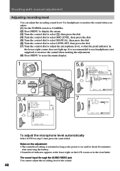
The sound input through the AUDIO/VIDEO jack You cannot adjust the recording level of the ...headphones (not supplied) to monitor the sound when making the adjustment. (8) Press MENU to adjust the microphone level, so that the peak indicator in the lower-right corner does not light up. Notes on the... L E V E L REMA I N RETURN AUTO 7 TAPE SET MI C LEVEL LEVEL SET RETURN [ MENU ] : END [ MENU ] : END To adjust the microphone level automatically Select AUTO in the viewfinder. Use headphones to monitor the sound when you adjust. (1) Set the POWER switch to CAMERA. (2) Press MENU to...
The sound input through the AUDIO/VIDEO jack You cannot adjust the recording level of the ...headphones (not supplied) to monitor the sound when making the adjustment. (8) Press MENU to adjust the microphone level, so that the peak indicator in the lower-right corner does not light up. Notes on the... L E V E L REMA I N RETURN AUTO 7 TAPE SET MI C LEVEL LEVEL SET RETURN [ MENU ] : END [ MENU ] : END To adjust the microphone level automatically Select AUTO in the viewfinder. Use headphones to monitor the sound when you adjust. (1) Set the POWER switch to CAMERA. (2) Press MENU to...

Operating Instructions
Page 64
... display the menu or title menu while superimposing a title, the title is not recorded while the menu or title menu is displayed, LCD BRIGHT and microphone level indicators do not appear. 64 When you select the title size "LARGE" you can choose 9 positions. Title color changes as follows: WHITE ˜ YELLOW...
... display the menu or title menu while superimposing a title, the title is not recorded while the menu or title menu is displayed, LCD BRIGHT and microphone level indicators do not appear. 64 When you select the title size "LARGE" you can choose 9 positions. Title color changes as follows: WHITE ˜ YELLOW...

Operating Instructions
Page 88
.... The original sound will not be erased. Connecting the microphone with the Remote Commander. Connecting the microphone with the MIC jack MIC (PLUG IN POWER) Ç : Signal flow Microphone (not supplied) Note You can check the recorded picture and sound by connecting the AUDIO/VIDEO jack to your recorded tape by specifying the starting...
.... The original sound will not be erased. Connecting the microphone with the Remote Commander. Connecting the microphone with the MIC jack MIC (PLUG IN POWER) Ç : Signal flow Microphone (not supplied) Note You can check the recorded picture and sound by connecting the AUDIO/VIDEO jack to your recorded tape by specifying the starting...
Operating Instructions
Page 89
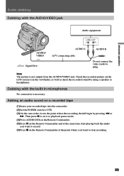
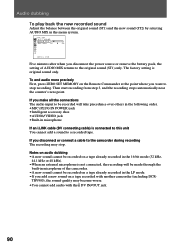
...on a recorded tape (1) Insert your recorded tape into the camcorder. (2) Set the POWER switch to stop recording. 89 Adding an audio sound on the LCD screen or in microphones No connection is not output from the AUDIO/VIDEO jack. Note The picture is necessary. Then press P ...p on the Remote Commander at the point where you want to VTR. (3) On the camcorder, locate the point where the recording should begin by using a speaker or headphones. Dubbing with the AUDIO/VIDEO jack Audio equipment AUDIO/ VIDEO Ç : Signal flow LINE OUT L R AUDIO L AUDIO R A/V connecting cable ...
...on a recorded tape (1) Insert your recorded tape into the camcorder. (2) Set the POWER switch to stop recording. 89 Adding an audio sound on the LCD screen or in microphones No connection is not output from the AUDIO/VIDEO jack. Note The picture is necessary. Then press P ...p on the Remote Commander at the point where you want to VTR. (3) On the camcorder, locate the point where the recording should begin by using a speaker or headphones. Dubbing with the AUDIO/VIDEO jack Audio equipment AUDIO/ VIDEO Ç : Signal flow LINE OUT L R AUDIO L AUDIO R A/V connecting cable ...
Operating Instructions
Page 90
... at the point where you disconnect the power source or remove the battery pack, the setting of the camcorder. •A new sound cannot be recorded will be made through the built-in microphone of AUDIO MIX returns to stop . The factory setting is not connected, the recording will take precedence...following order. •MIC (PLUG IN POWER) jack •Intelligent accessory shoe •AUDIO/VIDEO jack •Built-in the 16-bit mode (32 kHz, 44.1 kHz or 48 kHz). •When an external microphone is original sound only. TRV900), the sound quality may stop recording. If you make all...
... at the point where you disconnect the power source or remove the battery pack, the setting of the camcorder. •A new sound cannot be recorded will be made through the built-in microphone of AUDIO MIX returns to stop . The factory setting is not connected, the recording will take precedence...following order. •MIC (PLUG IN POWER) jack •Intelligent accessory shoe •AUDIO/VIDEO jack •Built-in the 16-bit mode (32 kHz, 44.1 kHz or 48 kHz). •When an external microphone is original sound only. TRV900), the sound quality may stop recording. If you make all...
Operating Instructions
Page 133
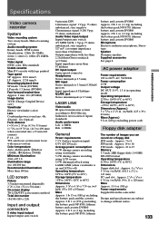
...(Charge Coupled Device 1/4") Viewfinder Electric viewfinder (color) Lens Combined power zoom lens, 48x (Digital), 12x (Optical) Focal distance f =3/16 to 2 1/8 in. (4.3 to 51.6 mm... lLANC jack Stereo miniminijack (ø 2.5 mm) LASER LINK Video/audio IR space transmission system according to change without notice. ...) Mass Approx. 13.4 oz (380 g) Power requirements Supplied from the camcorder. Design and specifications are subject to EIAJ (Electric Industries Association of images ...Microphone Electret condenser microphone, Stereo type Speaker Dynamic-speaker Supplied accessories See page 6.
...(Charge Coupled Device 1/4") Viewfinder Electric viewfinder (color) Lens Combined power zoom lens, 48x (Digital), 12x (Optical) Focal distance f =3/16 to 2 1/8 in. (4.3 to 51.6 mm... lLANC jack Stereo miniminijack (ø 2.5 mm) LASER LINK Video/audio IR space transmission system according to change without notice. ...) Mass Approx. 13.4 oz (380 g) Power requirements Supplied from the camcorder. Design and specifications are subject to EIAJ (Electric Industries Association of images ...Microphone Electret condenser microphone, Stereo type Speaker Dynamic-speaker Supplied accessories See page 6.

Operating Instructions
Page 135
Additional information Identifying the parts !§ !¶ !• !ª !§ Tape transport buttons (p. 22) π STOP (stop) 0 REW (rewind) · PLAY (playback) ) FF (fast-forward) P PAUSE (pause) r REC (record) !¶ Focus ring (p. 58) !• LASER LINK transmitter (p. 71) / Remote sensor (p. 140) !ª Built-in microphone @º @¡ @™ @£ @¢ @∞ @º Power zoom lever (p. 14) @¡LASER LINK button (p. 71) @™ Viewfinder (p. 13) @£ Display window (p. 142) @¢ FOCUS switch (p. 58) @∞ PUSH AUTO button (p. 58) 135
Additional information Identifying the parts !§ !¶ !• !ª !§ Tape transport buttons (p. 22) π STOP (stop) 0 REW (rewind) · PLAY (playback) ) FF (fast-forward) P PAUSE (pause) r REC (record) !¶ Focus ring (p. 58) !• LASER LINK transmitter (p. 71) / Remote sensor (p. 140) !ª Built-in microphone @º @¡ @™ @£ @¢ @∞ @º Power zoom lever (p. 14) @¡LASER LINK button (p. 71) @™ Viewfinder (p. 13) @£ Display window (p. 142) @¢ FOCUS switch (p. 58) @∞ PUSH AUTO button (p. 58) 135

Operating Instructions
Page 137
... pull out the accessory. 137 To remove an accessory, loosen the screw, and then press down and push it to optional accessories such as a video light or microphone. Additional information Identifying the parts $ª %º $§ %¡ $¶ $• $§ Access lamp (p. 93) $¶ DC IN jack (p. 8) $• Hooks for further information...
... pull out the accessory. 137 To remove an accessory, loosen the screw, and then press down and push it to optional accessories such as a video light or microphone. Additional information Identifying the parts $ª %º $§ %¡ $¶ $• $§ Access lamp (p. 93) $¶ DC IN jack (p. 8) $• Hooks for further information...

Operating Instructions
Page 138
... and the screw may damage the camcorder. ^º ^¡ ^™ ^£ ^¢ %•Stand %ª MEMORY RELEASE lever ^º 2 (headphones) jack (p. 22) ^¡ AUDIO/VIDEO jack (p. 70, 82) ^™ S VIDEO jack (p. 34, 70, 82) ^£ Camera recording lamp ^¢ MIC jack (PLUG IN POWER) (p. 88) Connect an external microphone (not supplied). The l control jack...
... and the screw may damage the camcorder. ^º ^¡ ^™ ^£ ^¢ %•Stand %ª MEMORY RELEASE lever ^º 2 (headphones) jack (p. 22) ^¡ AUDIO/VIDEO jack (p. 70, 82) ^™ S VIDEO jack (p. 34, 70, 82) ^£ Camera recording lamp ^¢ MIC jack (PLUG IN POWER) (p. 88) Connect an external microphone (not supplied). The l control jack...

Operating Instructions
Page 141
... @¢ Audio mode indicator (p. 30) @∞ Microphone level indicator (p. 48) @§ Continuous mode indicator (p. 104) @¶ ND filter indicator (p. 49) @• Video flash ready indicator (p. 33) @ª Self-timer ...indicator (p. 18) 141 SCAN 7 NEG . ART 8 . -3 9 10000 0 F 1 . 6 1 2 dB AE A !¡ !™ !£ !¢ !∞ 1 Cassette memory indicator (p. 116) 2 Remaining battery indicator (p. 120) 3 Zoom indicator (p. 14) /Exposure indicator (p. 44)/ Data file name indicator (p. 92) 4 Digital...
... @¢ Audio mode indicator (p. 30) @∞ Microphone level indicator (p. 48) @§ Continuous mode indicator (p. 104) @¶ ND filter indicator (p. 49) @• Video flash ready indicator (p. 33) @ª Self-timer ...indicator (p. 18) 141 SCAN 7 NEG . ART 8 . -3 9 10000 0 F 1 . 6 1 2 dB AE A !¡ !™ !£ !¢ !∞ 1 Cassette memory indicator (p. 116) 2 Remaining battery indicator (p. 120) 3 Zoom indicator (p. 14) /Exposure indicator (p. 44)/ Data file name indicator (p. 92) 4 Digital...
Operating Instructions
Page 145
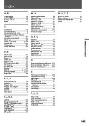
...31 C Car battery 26 Cassette memory 4 Charging battery pack 8 Charging vanadium-lithium battery 117 Cleaning video heads 123 Clock set 118 Color TV system 4, 126 Connection 70, 82 Continuous 103 COPY INHIBIT 116... D, E Data Code 81 Date search 74 Demo 142 DISPLAY 22 Digital zoom 15 DV connecting cable 83 DV format 116 DV IN/OUT 83 Editing 82 EJECT ... 44 Manual focus 57 Memory card 91 Memory card slot 91 Memory Stick 91 Menu system 27 Microphone level 48 Mirror mode 17 Moisture condensation 123 Normal charge 8 O, P, Q PHOTO 33 Photo scan...
...31 C Car battery 26 Cassette memory 4 Charging battery pack 8 Charging vanadium-lithium battery 117 Cleaning video heads 123 Clock set 118 Color TV system 4, 126 Connection 70, 82 Continuous 103 COPY INHIBIT 116... D, E Data Code 81 Date search 74 Demo 142 DISPLAY 22 Digital zoom 15 DV connecting cable 83 DV format 116 DV IN/OUT 83 Editing 82 EJECT ... 44 Manual focus 57 Memory card 91 Memory card slot 91 Memory Stick 91 Menu system 27 Microphone level 48 Mirror mode 17 Moisture condensation 123 Normal charge 8 O, P, Q PHOTO 33 Photo scan...


