
Operating Instructions
Page 2
...cabinet. DAV-IS50 Serial No 2US WARNING The following measures: - Other versions may cause harmful interference to comply with dry cloth. 7) Do not block any ventilation openings. This equipment has been tested and found to radio communications. These limits are provided for help. Connect the ...or more of the following FCC statement applies only to persons. Consult the dealer or an experienced radio/TV technician for your Sony dealer regarding this apparatus to excessive heat such as radiators, heat registers, stoves, or other . Batteries or batteries installed ...
...cabinet. DAV-IS50 Serial No 2US WARNING The following measures: - Other versions may cause harmful interference to comply with dry cloth. 7) Do not block any ventilation openings. This equipment has been tested and found to radio communications. These limits are provided for help. Connect the ...or more of the following FCC statement applies only to persons. Consult the dealer or an experienced radio/TV technician for your Sony dealer regarding this apparatus to excessive heat such as radiators, heat registers, stoves, or other . Batteries or batteries installed ...
Operating Instructions
Page 3
...-40 of the NEC that provides guidelines for long periods of sound between S-AIR products wirelessly. When a cart is connected to qualified service personnel. Note to CATV system installer: This reminder is used with the S-AIR function, which allows transmission of time. 14) Refer all servicing to...the wall socket immediately in this apparatus during lightning storms or when unused for proper grounding and, in this system so that the cable ground shall be connected to the grounding system of the building, as an option (the S-AIR product lineup differs depending on the area). 10) ...
...-40 of the NEC that provides guidelines for long periods of sound between S-AIR products wirelessly. When a cart is connected to qualified service personnel. Note to CATV system installer: This reminder is used with the S-AIR function, which allows transmission of time. 14) Refer all servicing to...the wall socket immediately in this apparatus during lightning storms or when unused for proper grounding and, in this system so that the cable ground shall be connected to the grounding system of the building, as an option (the S-AIR product lineup differs depending on the area). 10) ...
Operating Instructions
Page 4
Table of Contents About This Operating Instructions.......... 3 About the S-AIR function 3 Playable Discs 6 Getting Started Step 1: Positioning the Speakers........... 11 Step 2: Connecting the System 17 Step 3: Performing the Quick Setup ..... 25 Basic Operations Playing a Disc 29 Enjoying the Radio or Other Components 32 Enjoying Sound from all Speakers ...Functions Presetting Radio Stations 56 Listening to the Radio 57 Control for HDMI/External Audio Device Using the Control for HDMI Function for "BRAVIA" Sync 59 Using the DIGITAL MEDIA PORT Adapter 62 Using an S-AIR Product 63 4US
Table of Contents About This Operating Instructions.......... 3 About the S-AIR function 3 Playable Discs 6 Getting Started Step 1: Positioning the Speakers........... 11 Step 2: Connecting the System 17 Step 3: Performing the Quick Setup ..... 25 Basic Operations Playing a Disc 29 Enjoying the Radio or Other Components 32 Enjoying Sound from all Speakers ...Functions Presetting Radio Stations 56 Listening to the Radio 57 Control for HDMI/External Audio Device Using the Control for HDMI Function for "BRAVIA" Sync 59 Using the DIGITAL MEDIA PORT Adapter 62 Using an S-AIR Product 63 4US
Operating Instructions
Page 16
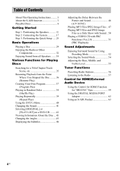
...shown below. Note Be sure to match the speaker cords to the appropriate speaker terminals: 3 to +, and # to follow these precautions when connecting the speakers. Make sure the bare wire of each other due to be distorted. 16US With the catch facing down, press and hold the ...connector. If the cords are reversed, the sound will lack bass and may damage the system. Stripped speaker cord is touching another speaker cord, such as the jacks to excessive removal of the speakers may be connected. 3 # Black Do not catch the speaker cords insulation in the speaker terminals. Tip...
...shown below. Note Be sure to match the speaker cords to the appropriate speaker terminals: 3 to +, and # to follow these precautions when connecting the speakers. Make sure the bare wire of each other due to be distorted. 16US With the catch facing down, press and hold the ...connector. If the cords are reversed, the sound will lack bass and may damage the system. Stripped speaker cord is touching another speaker cord, such as the jacks to excessive removal of the speakers may be connected. 3 # Black Do not catch the speaker cords insulation in the speaker terminals. Tip...
Operating Instructions
Page 17
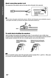
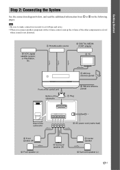
...component with a volume control, turn up the volume of the other components to 6 on the following pages. Getting Started Step 2: Connecting the System See the connection diagram below, and read the additional information from 1 to a level where sound is not distorted. 4 VCR, digital satellite receiver... 5 AM loop antenna (aerial) Front of the control unit Bottom of the subwoofer 1 Plug 5 FM wire antenna (aerial) Rear of the subwoofer SYSTEM CONTROL ONLY FOR HCD-IS50 SPEAKER ONLY FOR SS-IS15 FRONT R FRONT L SUR R SUR L CENTER 6 AC power cord (mains lead) 2 Front speaker (R) 2 Front...
...component with a volume control, turn up the volume of the other components to 6 on the following pages. Getting Started Step 2: Connecting the System See the connection diagram below, and read the additional information from 1 to a level where sound is not distorted. 4 VCR, digital satellite receiver... 5 AM loop antenna (aerial) Front of the control unit Bottom of the subwoofer 1 Plug 5 FM wire antenna (aerial) Rear of the subwoofer SYSTEM CONTROL ONLY FOR HCD-IS50 SPEAKER ONLY FOR SS-IS15 FRONT R FRONT L SUR R SUR L CENTER 6 AC power cord (mains lead) 2 Front speaker (R) 2 Front...
Operating Instructions
Page 18
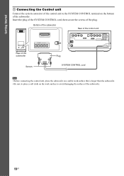
Bottom of the subwoofer Rear of the control unit Rear of the subwoofer SYSTEM CONTROL ONLY FOR HCD-IS50 SPEAKER ONLY FOR SS-IS15 FRONT R FRONT L SUR R SUR L CENTER Plug DMPORT Screws SYSTEM CONTROL cord Note • Before connecting the control unit, place the subwoofer on a stable work surface that is larger than the subwoofer...
Bottom of the subwoofer Rear of the control unit Rear of the subwoofer SYSTEM CONTROL ONLY FOR HCD-IS50 SPEAKER ONLY FOR SS-IS15 FRONT R FRONT L SUR R SUR L CENTER Plug DMPORT Screws SYSTEM CONTROL cord Note • Before connecting the control unit, place the subwoofer on a stable work surface that is larger than the subwoofer...
Operating Instructions
Page 19
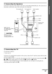
... of the speaker cords has the same color as follows: • Video cord (1) To listen to TV sound from A (standard) to be connected. Gray SYSTEM CONTROL ONLY FOR HCD-IS50 SPEAKER ONLY FOR SS-IS15 FRONT R FRONT L SUR R SUR L CENTER Speaker cords Green White Bottom of the subwoofer Blue Speaker cords Surround speaker...
... of the speaker cords has the same color as follows: • Video cord (1) To listen to TV sound from A (standard) to be connected. Gray SYSTEM CONTROL ONLY FOR HCD-IS50 SPEAKER ONLY FOR SS-IS15 FRONT R FRONT L SUR R SUR L CENTER Speaker cords Green White Bottom of the subwoofer Blue Speaker cords Surround speaker...
Operating Instructions
Page 20
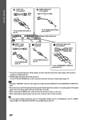
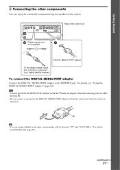
... 20US Note • During the "DMPORT" function, video signal is not output from the HDMI OUT and COMPONENT VIDEO OUT jacks. • The system can connect another component, such as a VCR, digital satellite receiver, or PlayStation, to progressive format (page 28). ** HDMI (High-Definition Multimedia Interface) If ...your TV has the HDMI jack, use this connection and set the output signal of the system to the TV AUDIO IN jacks (A) or TV DIGITAL IN OPTICAL jack (B) instead of jacks are the same. • ...
... 20US Note • During the "DMPORT" function, video signal is not output from the HDMI OUT and COMPONENT VIDEO OUT jacks. • The system can connect another component, such as a VCR, digital satellite receiver, or PlayStation, to progressive format (page 28). ** HDMI (High-Definition Multimedia Interface) If ...your TV has the HDMI jack, use this connection and set the output signal of the system to the TV AUDIO IN jacks (A) or TV DIGITAL IN OPTICAL jack (B) instead of jacks are the same. • ...
Operating Instructions
Page 21
...84). A Tip • You can enjoy the connected component using the speakers of another component (e.g.: digital satellite receiver) To connect the DIGITAL MEDIA PORT adapter Connect the DIGITAL MEDIA PORT adapter to /from the control unit while the system is turned on. When disconnecting, pull out while ...pressing A. • Do not connect or disconnect the DIGITAL MEDIA PORT...
...84). A Tip • You can enjoy the connected component using the speakers of another component (e.g.: digital satellite receiver) To connect the DIGITAL MEDIA PORT adapter Connect the DIGITAL MEDIA PORT adapter to /from the control unit while the system is turned on. When disconnecting, pull out while ...pressing A. • Do not connect or disconnect the DIGITAL MEDIA PORT...
Operating Instructions
Page 22
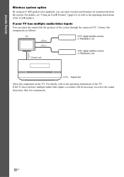
... on the TV. If the TV does not have multiple audio/video inputs, a switcher will be necessary to the operating instructions of the TV. Connect the components as follows. Getting Started Wireless system option By using an S-AIR product (not supplied), you can enjoy the sound with the speakers of the... system through the connected TV. TV VCR, digital satellite receiver or PlayStation, etc. For details, refer to the operating instructions of the S-AIR product. For details, see "Using an...
... on the TV. If the TV does not have multiple audio/video inputs, a switcher will be necessary to the operating instructions of the TV. Connect the components as follows. Getting Started Wireless system option By using an S-AIR product (not supplied), you can enjoy the sound with the speakers of the... system through the connected TV. TV VCR, digital satellite receiver or PlayStation, etc. For details, refer to the operating instructions of the S-AIR product. For details, see "Using an...
Operating Instructions
Page 23
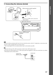
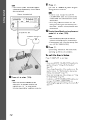
... Antenna (Aerial) AM loop antenna (aerial) (supplied) A B Note • Cord (A) or cord (B) can be connected to fully extend the FM wire antenna (aerial). • After connecting the FM wire antenna (aerial), keep it as horizontal as shown below. Outdoor FM antenna (aerial) Control unit ANTENNA AM FM 75 COAXIAL... of the control unit DMPORT FM wire antenna (aerial) (supplied) Note • Keep the AM loop antenna (aerial) and cord away from the system or other AV components, as noise may result. • Be sure to either terminal. Rear of the AM loop antenna (aerial) for best AM...
... Antenna (Aerial) AM loop antenna (aerial) (supplied) A B Note • Cord (A) or cord (B) can be connected to fully extend the FM wire antenna (aerial). • After connecting the FM wire antenna (aerial), keep it as horizontal as shown below. Outdoor FM antenna (aerial) Control unit ANTENNA AM FM 75 COAXIAL... of the control unit DMPORT FM wire antenna (aerial) (supplied) Note • Keep the AM loop antenna (aerial) and cord away from the system or other AV components, as noise may result. • Be sure to either terminal. Rear of the AM loop antenna (aerial) for best AM...
Operating Instructions
Page 24
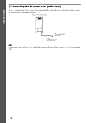
Rear of the subwoofer to a wall outlet (mains), connect all the speakers to the subwoofer (page 19). Getting Started 6 Connecting the AC power cord (mains lead) Before connecting the AC power cord (mains lead) of the subwoofer To a wall outlet (mains) AC power cord (mains lead) Note • After connecting the AC power cord (mains lead), wait about 20 seconds before turning on the power by pressing "/1. 24US
Rear of the subwoofer to a wall outlet (mains), connect all the speakers to the subwoofer (page 19). Getting Started 6 Connecting the AC power cord (mains lead) Before connecting the AC power cord (mains lead) of the subwoofer To a wall outlet (mains) AC power cord (mains lead) Note • After connecting the AC power cord (mains lead), wait about 20 seconds before turning on the power by pressing "/1. 24US
Operating Instructions
Page 25
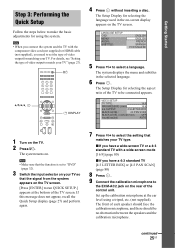
...TV type. x If you need to set to "DVD" (page 32). 3 Switch the input selector on the TV screen. Note • When you connect the system and the TV with a wide-screen mode [16:9] (page 80) x If you have a wide-screen TV or a 4:3 standard TV with the component...4:3 standard TV [4:3 LETTER BOX] or [4:3 PAN SCAN] (page 80) 8 Press . 9 Connect the calibration microphone to the ECM-AC2 jack on the TV screen. [Press [ENTER] to run QUICK SETUP.] appears at the ear level using the system. continued 25US VIDEO SETUP TV TYPE: 16:9 PROGRESSIVE (COMPONENT OUT): 16:9 4:3 OUTPUT: 4:3 ...
...TV type. x If you need to set to "DVD" (page 32). 3 Switch the input selector on the TV screen. Note • When you connect the system and the TV with a wide-screen mode [16:9] (page 80) x If you have a wide-screen TV or a 4:3 standard TV with the component...4:3 standard TV [4:3 LETTER BOX] or [4:3 PAN SCAN] (page 80) 8 Press . 9 Connect the calibration microphone to the ECM-AC2 jack on the TV screen. [Press [ENTER] to run QUICK SETUP.] appears at the ear level using the system. continued 25US VIDEO SETUP TV TYPE: 16:9 PROGRESSIVE (COMPONENT OUT): 16:9 4:3 OUTPUT: 4:3 ...
Operating Instructions
Page 26
...operate following steps with measurement. 12 Unplug the calibration microphone and press C/c to select [YES]. Be quiet during the measurement (which the system is used for the Speakers" (page 85). • If you cancel [AUTO CALIBRATION], perform the speaker settings in the measurement area and...for the supplied calibration microphone only. Quick Setup is output when [AUTO CALIBRATION] starts. Tip • If you change any Step. Do not connect other microphones. Note • Loud test sound is finished. Note • The environment of the room in any of the settings, see "...
...operate following steps with measurement. 12 Unplug the calibration microphone and press C/c to select [YES]. Be quiet during the measurement (which the system is used for the Speakers" (page 85). • If you cancel [AUTO CALIBRATION], perform the speaker settings in the measurement area and...for the supplied calibration microphone only. Quick Setup is output when [AUTO CALIBRATION] starts. Tip • If you change any Step. Do not connect other microphones. Note • Loud test sound is finished. Note • The environment of the room in any of the settings, see "...
Operating Instructions
Page 27
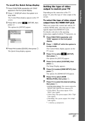
...signals output from the HDMI OUT jack When you connect the control unit and the TV with the TV/projector, etc. 1 Press FUNCTION repeatedly until "DVD" appears in the front panel display. 2 Press DISPLAY when the system is in stop mode. The Control Menu display...Press X/x to select press . [SETUP], then The options for the connected TV. • [1920×1080i]: The system outputs 1920 × 1080i* video signals. • [1280×720p]: The system outputs 1280 × 720p* video signals. • [720×480p]: The system outputs 720 × 480p* video signals. * i: interlace, p:...
...signals output from the HDMI OUT jack When you connect the control unit and the TV with the TV/projector, etc. 1 Press FUNCTION repeatedly until "DVD" appears in the front panel display. 2 Press DISPLAY when the system is in stop mode. The Control Menu display...Press X/x to select press . [SETUP], then The options for the connected TV. • [1920×1080i]: The system outputs 1920 × 1080i* video signals. • [1280×720p]: The system outputs 1280 × 720p* video signals. • [720×480p]: The system outputs 720 × 480p* video signals. * i: interlace, p:...
Operating Instructions
Page 28
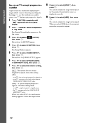
... jacks other than the COMPONENT VIDEO OUT jacks. [ON]: The system outputs progressive signals. your TV is connected to select the desired setting, then press . [OFF]: The system does not output progressive signals. the TV is connected to select [START], then press . When you select [ON],... the confirmation display appears. The system outputs the progressive signal for displaying TV images which reduces...
... jacks other than the COMPONENT VIDEO OUT jacks. [ON]: The system outputs progressive signals. your TV is connected to select the desired setting, then press . [OFF]: The system does not output progressive signals. the TV is connected to select [START], then press . When you select [ON],... the confirmation display appears. The system outputs the progressive signal for displaying TV images which reduces...

Operating Instructions
Page 30
... screen. The volume level appears on the TV screen and in the front panel display and the system is connected to on, the TV that is ready for HDMI function. Unless the mode of the system is pulled in the front panel display. 5 Press H on the remote, or touch N (soft-touch button) on..., see page 59. For details, see page 59. 30US Tip • When you can be sync-operated with an HDMI cable, you connect the system and TV with the system. Labeled side facing to upper surface The disc is drawn into the disc slot until the disc is set the Control for HDMI...
... screen. The volume level appears on the TV screen and in the front panel display and the system is connected to on, the TV that is ready for HDMI function. Unless the mode of the system is pulled in the front panel display. 5 Press H on the remote, or touch N (soft-touch button) on..., see page 59. For details, see page 59. 30US Tip • When you can be sync-operated with an HDMI cable, you connect the system and TV with the system. Labeled side facing to upper surface The disc is drawn into the disc slot until the disc is set the Control for HDMI...
Operating Instructions
Page 32
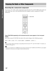
...". Basic Operations Enjoying the Radio or Other Components Selecting the connected component You can assign a digital sound input corresponding with the components for further information. Refer to the TV or SAT/CABLE jacks on the rear of the system changes in the front panel display. Note • When you... press FUNCTION, the mode of the control unit. DVD t FM t AM t TV t SAT/CABLE t DMPORT t DVD t ... Tip • You can use both the TV (AUDIO IN) jacks (analog connection) and TV (DIGITAL IN ...
...". Basic Operations Enjoying the Radio or Other Components Selecting the connected component You can assign a digital sound input corresponding with the components for further information. Refer to the TV or SAT/CABLE jacks on the rear of the system changes in the front panel display. Note • When you... press FUNCTION, the mode of the control unit. DVD t FM t AM t TV t SAT/CABLE t DMPORT t DVD t ... Tip • You can use both the TV (AUDIO IN) jacks (analog connection) and TV (DIGITAL IN ...

Operating Instructions
Page 33
.... • "ATT ON": You can attenuates the input level. To prevent distortion, reduce the input level on the component connected. The system menu turns off. Note • "ATTENUATE" appears only when the function is not a malfunction and will depend on the control unit. FUNCTION... in the front panel display. 2 Press SYSTEM MENU. 3 Press X/x repeatedly until "ATTENUATE" appears in the front panel display, then press or c. 4 Press X/x to the "TV" function. 33US Basic Operations Changing the input level of the sound from connected components Distortion may occur when you listen to...
.... • "ATT ON": You can attenuates the input level. To prevent distortion, reduce the input level on the component connected. The system menu turns off. Note • "ATTENUATE" appears only when the function is not a malfunction and will depend on the control unit. FUNCTION... in the front panel display. 2 Press SYSTEM MENU. 3 Press X/x repeatedly until "ATTENUATE" appears in the front panel display, then press or c. 4 Press X/x to the "TV" function. 33US Basic Operations Changing the input level of the sound from connected components Distortion may occur when you listen to...
Operating Instructions
Page 34
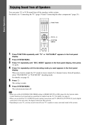
...DEC. MODE" appears in [HDMI SETUP] to [ON] (page 60), the System Audio Control function is made. 6 Press SYSTEM MENU. For details, see "Connecting the TV" (page 19) and "Connecting the other components" (page 21). The system menu turns off your TV's speaker to output the TV sound or stereo sound of... you use both the TV (AUDIO IN) jacks (analog connection) and TV (DIGITAL IN OPTICAL) jack (digital connection) at the same time, the digital connection takes priority. • Depending on your TV, you want appears in this system. The setting is activated and no sound may need to turn...
...DEC. MODE" appears in [HDMI SETUP] to [ON] (page 60), the System Audio Control function is made. 6 Press SYSTEM MENU. For details, see "Connecting the TV" (page 19) and "Connecting the other components" (page 21). The system menu turns off your TV's speaker to output the TV sound or stereo sound of... you use both the TV (AUDIO IN) jacks (analog connection) and TV (DIGITAL IN OPTICAL) jack (digital connection) at the same time, the digital connection takes priority. • Depending on your TV, you want appears in this system. The setting is activated and no sound may need to turn...


