
Service Manual
Page 1
... CD CIRCUIT 5-1 [2] VOLTAGE 5-2 CHAPTER 6. DIAGRAMS [1] BLOCK DIAGRAM 4-1 CHAPTER 5. FLOWCHART [1] TROUBLESHOOTING 7-1 CHAPTER 8. The contents are subject to be used for after sales service only. ADJUSTMENTS [1] ADJUSTMENT 2-1 [2] TEST MODE 2-3 [3] Standard Specification of user-safety the set should be restored to its original condition and only parts identical to those specified be used . CIRCUIT SCHEMATICS AND PARTS LAYOUT [1] NOTES ON SCHEMATIC DIAGRAM 6-1 [2] TYPES OF TRANSISTOR AND LED 6-1 [3] WIRING SIDE OF P.W.BOARD/SCHE- GENERAL...
... CD CIRCUIT 5-1 [2] VOLTAGE 5-2 CHAPTER 6. DIAGRAMS [1] BLOCK DIAGRAM 4-1 CHAPTER 5. FLOWCHART [1] TROUBLESHOOTING 7-1 CHAPTER 8. The contents are subject to be used for after sales service only. ADJUSTMENTS [1] ADJUSTMENT 2-1 [2] TEST MODE 2-3 [3] Standard Specification of user-safety the set should be restored to its original condition and only parts identical to those specified be used . CIRCUIT SCHEMATICS AND PARTS LAYOUT [1] NOTES ON SCHEMATIC DIAGRAM 6-1 [2] TYPES OF TRANSISTOR AND LED 6-1 [3] WIRING SIDE OF P.W.BOARD/SCHE- GENERAL...
Service Manual
Page 2
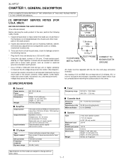
... following manner. * Plug the AC line cord directly into 6 ohms from 100 Hz to 20 kHz, 10% total harmonic distortion Speakers: 6 ohms Headphones: 16 - 50 ohms (recommended: 32 ohms) Subwoofer pre-out (audio signal): 200 mV/10 k ohms at 70 Hz Video/Auxiliary (audio signal): 500 mV/47 k ohms 5-disc multi-play compact disc player Non-contact, 3-beam semiconductor laser pickup 1-bit D/A converter 20 - 20,000 Hz 90 dB (1 kHz) I Tuner Frequency range FM: 87.5 - 108...
... following manner. * Plug the AC line cord directly into 6 ohms from 100 Hz to 20 kHz, 10% total harmonic distortion Speakers: 6 ohms Headphones: 16 - 50 ohms (recommended: 32 ohms) Subwoofer pre-out (audio signal): 200 mV/10 k ohms at 70 Hz Video/Auxiliary (audio signal): 500 mV/47 k ohms 5-disc multi-play compact disc player Non-contact, 3-beam semiconductor laser pickup 1-bit D/A converter 20 - 20,000 Hz 90 dB (1 kHz) I Tuner Frequency range FM: 87.5 - 108...
Service Manual
Page 3
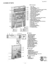
.... Subwoofer Pre-output Jack I Display 1. Headphone Jack 10. Tape Button 24. Tuning Down Button 12 3 1 4 5678 9 10 11 12 13 14 15 16 17 18 19 20 4 5 6 7 I Speaker system 2 8 1. AC Power Cord 4. Speaker Wire 3 2 4 1 - 2 Disc Play or Repeat, Tape Forward Play Button 20. Sleep Indicator 6. Cooling Fan 2. Disc Number Indicators 2. Tape Reverse Play Indicator 14. FM Stereo Receiving Indicator 12. Tape Reverse Mode Indicator 16. FM 75 Ohms Antenna Terminal 5. Disc Track Down or Fast Reverse, Tape Fast Wind, Tuner Preset Down, Time Down Button...
.... Subwoofer Pre-output Jack I Display 1. Headphone Jack 10. Tape Button 24. Tuning Down Button 12 3 1 4 5678 9 10 11 12 13 14 15 16 17 18 19 20 4 5 6 7 I Speaker system 2 8 1. AC Power Cord 4. Speaker Wire 3 2 4 1 - 2 Disc Play or Repeat, Tape Forward Play Button 20. Sleep Indicator 6. Cooling Fan 2. Disc Number Indicators 2. Tape Reverse Play Indicator 14. FM Stereo Receiving Indicator 12. Tape Reverse Mode Indicator 16. FM 75 Ohms Antenna Terminal 5. Disc Track Down or Fast Reverse, Tape Fast Wind, Tuner Preset Down, Time Down Button...
Service Manual
Page 4
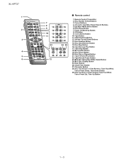
Character Input/Disc Direct Search Buttons 5. Equalizer Mode Select Button 6. Extra Bass Button 7. Disc Random Button 14. MP3 Disc Navigation Mode Select Button 24. Cursor Buttons 4. Power On/Stand-by Button 8. Disc Stop Button 16. Tape Forward Play Button 22. Tape Record Pause Button 23. Disc Number Select Buttons 3. CD Button 9. Volume Up and Down Buttons 13. Tape Reverse Play Button 17. Clock/Timer Button 27. Disc Track Up or Fast Forward, Tape Fast Wind, Tuner Preset Up, Time Up Button 1 - 3 Memory/Set Button 19. XL-HP737 1 2 3 4 5 6 7 8 13 9 14 10 ...
Character Input/Disc Direct Search Buttons 5. Equalizer Mode Select Button 6. Extra Bass Button 7. Disc Random Button 14. MP3 Disc Navigation Mode Select Button 24. Cursor Buttons 4. Power On/Stand-by Button 8. Disc Stop Button 16. Tape Forward Play Button 22. Tape Record Pause Button 23. Disc Number Select Buttons 3. CD Button 9. Volume Up and Down Buttons 13. Tape Reverse Play Button 17. Clock/Timer Button 27. Disc Track Up or Fast Forward, Tape Fast Wind, Tuner Preset Up, Time Up Button 1 - 3 Memory/Set Button 19. XL-HP737 1 2 3 4 5 6 7 8 13 9 14 10 ...
Service Manual
Page 5
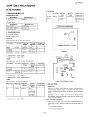
... time a disc is compensated inside the IC.) * Focus offset adjustment * Tracking offset adjustment 2 - 1 TUNER SECTION fL: Low-range frequency fH: High-range frequency • AM IF/RF Signal generator: 400 Hz, 30%, AM modulated Test Stage AM IF AM Band Coverage AM Tracking Frequency 450 kHz - 990 kHz Frequency Display 1,602 kHz 531 kHz 990 kHz Setting/ Adjusting Parts T351 (fL): T306 1.1 ± 0.1 V (fL): T303 Instrument Connection *1 *2 *1 *1. Input: Antenna Output: TP301 • Tape...
... time a disc is compensated inside the IC.) * Focus offset adjustment * Tracking offset adjustment 2 - 1 TUNER SECTION fL: Low-range frequency fH: High-range frequency • AM IF/RF Signal generator: 400 Hz, 30%, AM modulated Test Stage AM IF AM Band Coverage AM Tracking Frequency 450 kHz - 990 kHz Frequency Display 1,602 kHz 531 kHz 990 kHz Setting/ Adjusting Parts T351 (fL): T306 1.1 ± 0.1 V (fL): T303 Instrument Connection *1 *2 *1 *1. Input: Antenna Output: TP301 • Tape...

Service Manual
Page 6
... set inner position, inner switch cannot detect 'ON' level for the 5th times. 2 - 2 Can't detect CAM switch when CAM is detected, 'CHECKING' will be displayed instead of 'ERCD**'. 'ER-CD**' display will be displayed when error had been detected for 10 secs. XL-HP737 2) Tracking balance adjustment 3) Gain adjustment (The gain is moving . When it detect cam operation error during initialize process. TRAY error. Can't detect TRAY switch...
... set inner position, inner switch cannot detect 'ON' level for the 5th times. 2 - 2 Can't detect CAM switch when CAM is detected, 'CHECKING' will be displayed instead of 'ERCD**'. 'ER-CD**' display will be displayed when error had been detected for 10 secs. XL-HP737 2) Tracking balance adjustment 3) Gain adjustment (The gain is moving . When it detect cam operation error during initialize process. TRAY error. Can't detect TRAY switch...
Service Manual
Page 7
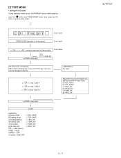
... To cancel : Power OFF Adjustment result automatically will display as below for each 2 sec: a) "FOF_XXXX" b) "TOF_XXXX" c) "TBAL_XX" d) "TGAN_XX" f) "FGAN_XX" g) "RFLS_XX" -------- then, press the CD button to page 2-4 key input. Do normal play. XL-HP737 2 - 3 When these following key is using manual. Do TOC IL. [2] TEST MODE • Setting the test mode During stand-by mode, press ON/STAND-BY button while pressing down the button and X-BASS/DEMO button. IL isn...
... To cancel : Power OFF Adjustment result automatically will display as below for each 2 sec: a) "FOF_XXXX" b) "TOF_XXXX" c) "TBAL_XX" d) "TGAN_XX" f) "FGAN_XX" g) "RFLS_XX" -------- then, press the CD button to page 2-4 key input. Do normal play. XL-HP737 2 - 3 When these following key is using manual. Do TOC IL. [2] TEST MODE • Setting the test mode During stand-by mode, press ON/STAND-BY button while pressing down the button and X-BASS/DEMO button. IL isn...
Service Manual
Page 8
Tracking OFF play from that specific point. key input. Tracking ON play at that specific point. key input. STOP Sliding the PICKUP with>, > button must only be 2 - 4 Adjustment result automatically will display as below for each 2 sec : a) "FOF_XXXX" b) "TOF_XXXX" c) "TBAL_XX" d) "TGAN_XX" f) "FGAN_XX" g) "RFLS_XX" key input. XL-HP737 A key input. Laser ON. key input.
Tracking OFF play from that specific point. key input. Tracking ON play at that specific point. key input. STOP Sliding the PICKUP with>, > button must only be 2 - 4 Adjustment result automatically will display as below for each 2 sec : a) "FOF_XXXX" b) "TOF_XXXX" c) "TBAL_XX" d) "TGAN_XX" f) "FGAN_XX" g) "RFLS_XX" key input. XL-HP737 A key input. Laser ON. key input.
Service Manual
Page 9
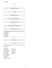
... of Stereo System Error Message Display Contents XL-HP737 CD TUNER Error Contents DISPLAY Pickup Mechanism Error. 'ER-CD01' CD Changer Mechanism Error. 'ER-CD**' (*) CD DSP Communication Error. Press OPEN/CLOSE button until "WAIT"--> "FINISHED" appears. 4. [3] Standard Specification of 'ER-CD**'. 'ER-CD**' display will show "S** B**". BEFORE TRANSPORTING THE UNIT The following process need to +B PROTECTION. ** is in hex valve. +B PROTECTION is ready for the 5 th times...
... of Stereo System Error Message Display Contents XL-HP737 CD TUNER Error Contents DISPLAY Pickup Mechanism Error. 'ER-CD01' CD Changer Mechanism Error. 'ER-CD**' (*) CD DSP Communication Error. Press OPEN/CLOSE button until "WAIT"--> "FINISHED" appears. 4. [3] Standard Specification of 'ER-CD**'. 'ER-CD**' display will show "S** B**". BEFORE TRANSPORTING THE UNIT The following process need to +B PROTECTION. ** is in hex valve. +B PROTECTION is ready for the 5 th times...
Service Manual
Page 15
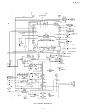
...) 9 ILLU_LED IXA021AW (Serial No.40203012~) PROTECT 29 RESET 10 80 S9 SYSTEM MICROCOMPUTER 56 100 G1 53 MOTOR/ SOLENOID DRIVER Q701,702 Q712~715 TAPE MECHANISM ASS'Y +B3 REMOTE SENSOR 1 RX701 2 +B10 3 +B10 KEY SW701-SW705 SW709-SW728 VOLUME VR701 +B9(SW_+5V) +B_PROTECT Q703 +B10 RESET VDD -20dBATT T_BIAS T_REC/PLAY VDD CLK DI DO CE LED707...
...) 9 ILLU_LED IXA021AW (Serial No.40203012~) PROTECT 29 RESET 10 80 S9 SYSTEM MICROCOMPUTER 56 100 G1 53 MOTOR/ SOLENOID DRIVER Q701,702 Q712~715 TAPE MECHANISM ASS'Y +B3 REMOTE SENSOR 1 RX701 2 +B10 3 +B10 KEY SW701-SW705 SW709-SW728 VOLUME VR701 +B9(SW_+5V) +B_PROTECT Q703 +B10 RESET VDD -20dBATT T_BIAS T_REC/PLAY VDD CLK DI DO CE LED707...

Service Manual
Page 21
... SW726 SW727 SW728 DESCRIPTION TUNING/TIME UP TUNING/TIME DOWN STOP PLAY PRESET UP X-BASS/DEMO EQUALIZER MEMORY/SET DIRECT PLAY DISC 1 DISC 2 DISC 3 DISC 4 DISC 5 OPEN/CLOSE POSITION ON...used: this model are subject to replace these parts with " " ( ) are used . (CH), (TH), (RH), (UJ): Temperature compensation (ML): Mylar type (P.P.): Polypropylene type • Schematic diagram and Wiring Side of P.W.Board for this symbol P means pico-farad and the unit of the set . Besides, the one measured by Digital Multimeter between such a section and the chassis with "Fusible" is a fuse...
... SW726 SW727 SW728 DESCRIPTION TUNING/TIME UP TUNING/TIME DOWN STOP PLAY PRESET UP X-BASS/DEMO EQUALIZER MEMORY/SET DIRECT PLAY DISC 1 DISC 2 DISC 3 DISC 4 DISC 5 OPEN/CLOSE POSITION ON...used: this model are subject to replace these parts with " " ( ) are used . (CH), (TH), (RH), (UJ): Temperature compensation (ML): Mylar type (P.P.): Polypropylene type • Schematic diagram and Wiring Side of P.W.Board for this symbol P means pico-farad and the unit of the set . Besides, the one measured by Digital Multimeter between such a section and the chassis with "Fusible" is a fuse...

Service Manual
Page 34
... WH(W) WHITE SW719 X-BASS /DEMO SW716 246 1357 STOPCNP702 SW715 TUNING/ TIME DOWN RD09 SW711 VIDEO/ AUX 1 Q703 G BK BLACK PK PINK 1 7 FFC702 DISPL TO TAPE MECHANISM PWB 6-19 10 - B H 1 2 3 4 5 6 Figure 6-14 WIRING SIDE OF P.W.BOARD (3/10) 6 - 14 XL-HP737 A SW728 OPEN/ CROSE SWITCH PWB-B2 B RD25 SW727 DISC 5 SW726 DISC 4 RD24 RD23 SW725 DISC 3 1 FFC706 6 SW724 C DISC 2 C721 RD22 RD21 RX701 REMOTE SENSOR 2 123 R756...
... WH(W) WHITE SW719 X-BASS /DEMO SW716 246 1357 STOPCNP702 SW715 TUNING/ TIME DOWN RD09 SW711 VIDEO/ AUX 1 Q703 G BK BLACK PK PINK 1 7 FFC702 DISPL TO TAPE MECHANISM PWB 6-19 10 - B H 1 2 3 4 5 6 Figure 6-14 WIRING SIDE OF P.W.BOARD (3/10) 6 - 14 XL-HP737 A SW728 OPEN/ CROSE SWITCH PWB-B2 B RD25 SW727 DISC 5 SW726 DISC 4 RD24 RD23 SW725 DISC 3 1 FFC706 6 SW724 C DISC 2 C721 RD22 RD21 RX701 REMOTE SENSOR 2 123 R756...

Service Manual
Page 42
... CD operation key is taken, check the following items. Remove the cabinet and follow the trouble shooting instructions. CD optical pickup Lens cleaner disc Parts code UDSKA0004AFZZ HOW TO USE 1. If it contact with the DSP). 2.2. When the CD does not function The CD section may be used on car CD players or on the laser pickup lens. You will automatically stop button...
... CD operation key is taken, check the following items. Remove the cabinet and follow the trouble shooting instructions. CD optical pickup Lens cleaner disc Parts code UDSKA0004AFZZ HOW TO USE 1. If it contact with the DSP). 2.2. When the CD does not function The CD section may be used on car CD players or on the laser pickup lens. You will automatically stop button...

Service Manual
Page 43
...0.00 V CH4 : 0.00 V CH2 Position 0.20 div =Trigger= Mode : AUTO Type : EDGE CH1 Delay : 0.0 ns Hold off : 0.2 µs Figure 1 1. Stopped CH1=500 mV DC 10:1 T FDO 1 CH3=500 mV DC 10:1 XL-HP737 500 ms/div (500 ms/div) NORM:20 kS/s TDO 3 =...Mode : AUTO Type : EDGE CH1 Delay : 0.0 ns Hold off : 0.2 µs Figure 2 7 - 2 Figure 3 Vp-p=1.0 V~1.3 V 0.5 mV/div,0.5 µsec/div Yes 2. No Check the laser diode driver Q1 peripheral circuit. (1) Focus-HF system check. Press the Tray1 CD Eject Button without inserting a disc, and try starting the playback operation...
...0.00 V CH4 : 0.00 V CH2 Position 0.20 div =Trigger= Mode : AUTO Type : EDGE CH1 Delay : 0.0 ns Hold off : 0.2 µs Figure 1 1. Stopped CH1=500 mV DC 10:1 T FDO 1 CH3=500 mV DC 10:1 XL-HP737 500 ms/div (500 ms/div) NORM:20 kS/s TDO 3 =...Mode : AUTO Type : EDGE CH1 Delay : 0.0 ns Hold off : 0.2 µs Figure 2 7 - 2 Figure 3 Vp-p=1.0 V~1.3 V 0.5 mV/div,0.5 µsec/div Yes 2. No Check the laser diode driver Q1 peripheral circuit. (1) Focus-HF system check. Press the Tray1 CD Eject Button without inserting a disc, and try starting the playback operation...

Service Manual
Page 46
...output. Analog power supply pin 2. Rough servo/phase control automatic switching monitor output pin."H" for rough servo and "L" for phase servo. ADAVDD/2 ADAVDD/2 ADAVDD/2 ADAVDD/2 - - - - B signal input pin. D signal input pin. Setting in Reset ZHI AVDD1/2 - - - - - TE signal output pin. Laser power control signal input pin. Thread control output pin. CLV playback mode. External deiemphasis setting pin, INternal signal monitor pin 1.Controlled by command from the EFM sig- Output - Focus control output pin. Digital power supply pin. connected...
...output. Analog power supply pin 2. Rough servo/phase control automatic switching monitor output pin."H" for rough servo and "L" for phase servo. ADAVDD/2 ADAVDD/2 ADAVDD/2 ADAVDD/2 - - - - B signal input pin. D signal input pin. Setting in Reset ZHI AVDD1/2 - - - - - TE signal output pin. Laser power control signal input pin. Thread control output pin. CLV playback mode. External deiemphasis setting pin, INternal signal monitor pin 1.Controlled by command from the EFM sig- Output - Focus control output pin. Digital power supply pin. connected...

Service Manual
Page 47
... 02 outputs. Must always be connect to 0V, or set up as output pin ports and left open . Data output pin. (Try state output.) Interruption signal output pin. Error flag monitor pin, or sub code Controlled by commands from the micro- Any of pose I /O pin 4. Chip enable signal input pin. General pur- ports and connected to 0 V when unused.) Digital data output Left/Right channel data output pin. Phase comparison output pin...
... 02 outputs. Must always be connect to 0V, or set up as output pin ports and left open . Data output pin. (Try state output.) Interruption signal output pin. Error flag monitor pin, or sub code Controlled by commands from the micro- Any of pose I /O pin 4. Chip enable signal input pin. General pur- ports and connected to 0 V when unused.) Digital data output Left/Right channel data output pin. Phase comparison output pin...

Service Manual
Page 52
... circuit using an oscillator element. 8 - 7 The corresponding power supply level must also be provided to DVDD2 and DVDD5. (See the Allowable Operating Ranges specifications for at least 1 µs. 6) A 16.9344 MHz clock signal must be left open -drain output) Serial command data input. DRAM address output 6. DRAM address output 4. DRAM address output 1. Data continuity point detection complete flag (CD-DA mode, active high)/ SYNC error monitor...
... circuit using an oscillator element. 8 - 7 The corresponding power supply level must also be provided to DVDD2 and DVDD5. (See the Allowable Operating Ranges specifications for at least 1 µs. 6) A 16.9344 MHz clock signal must be left open -drain output) Serial command data input. DRAM address output 6. DRAM address output 4. DRAM address output 1. Data continuity point detection complete flag (CD-DA mode, active high)/ SYNC error monitor...
Service Manual
Page 56
Output Output Output Output Output Input Output Output Output Input Input Output Input (+) Power supply 5V. -20dB Attenuator. FL edge light control. CD Clock. CD Data input. Power abnormal detect. Tape motor control. RDS data. CD reset. CD WRQ input. MP3 Sub-micom CE. Clock output. Data input. Tape Run Pulse detect. Tape Fool Proof A & B SW. Volume jog input. Analog reference voltage 5V. Remocon input. Tape solenoid control. XL-HP737 IC701 RH-iXA003AWZZ: System Microcomputer (IXA003AW) (Serial No.40100012 ~ 40103011) (1/2) IC701 RH-iXA021AWZZ: System ...
Output Output Output Output Output Input Output Output Output Input Input Output Input (+) Power supply 5V. -20dB Attenuator. FL edge light control. CD Clock. CD Data input. Power abnormal detect. Tape motor control. RDS data. CD reset. CD WRQ input. MP3 Sub-micom CE. Clock output. Data input. Tape Run Pulse detect. Tape Fool Proof A & B SW. Volume jog input. Analog reference voltage 5V. Remocon input. Tape solenoid control. XL-HP737 IC701 RH-iXA003AWZZ: System Microcomputer (IXA003AW) (Serial No.40100012 ~ 40103011) (1/2) IC701 RH-iXA021AWZZ: System ...

Service Manual
Page 66
... Switch,Key Type [VIDEO/AUX] AC Switch,Key Type [TAPE] AC Switch,Key Type [REC/PAUSE] AC Switch,Key Type [TUNING/TIME UP] AC Switch,Key Type [TUNING/TIME DOWN] AC Switch,Key Type [STOP] AC Switch,Key Type [PLAY] AC Switch,Key Type [PRESET UP] AC Switch,Key Type [X-BASS/DEMO] AC Switch,Key Type [EQUALISER] AC Switch,Key Type [MEMORY/SET] AC Switch,Key Type [DIRECT PLAY] AC Switch,Key Type [DISC 1] AC Switch,Key Type [DISC 2] AC Switch...
... Switch,Key Type [VIDEO/AUX] AC Switch,Key Type [TAPE] AC Switch,Key Type [REC/PAUSE] AC Switch,Key Type [TUNING/TIME UP] AC Switch,Key Type [TUNING/TIME DOWN] AC Switch,Key Type [STOP] AC Switch,Key Type [PLAY] AC Switch,Key Type [PRESET UP] AC Switch,Key Type [X-BASS/DEMO] AC Switch,Key Type [EQUALISER] AC Switch,Key Type [MEMORY/SET] AC Switch,Key Type [DIRECT PLAY] AC Switch,Key Type [DISC 1] AC Switch,Key Type [DISC 2] AC Switch...
Service Manual
Page 67
... AK Rear Panel,Top AK Knob,VOLUME BC Tape Mechanism Ass'y -- Main/Power/Terminal -- Tape Mechanism PWB Ass'y AZ Clutch Ass'y Block -- Display/Switch/Led/Jack -- XL-HP737 NO. Motor with Pulley -- Belt,Main AL Pinch Roller Block,Right AL Pinch Roller Block,Left -- CD MP3 AD CD Motor (PWB Only) AE CD Changer Motor (PWB Only) OTHER SERVICE PARTS UDSKA0004AFZZ J AZ CD Optical...
... AK Rear Panel,Top AK Knob,VOLUME BC Tape Mechanism Ass'y -- Main/Power/Terminal -- Tape Mechanism PWB Ass'y AZ Clutch Ass'y Block -- Display/Switch/Led/Jack -- XL-HP737 NO. Motor with Pulley -- Belt,Main AL Pinch Roller Block,Right AL Pinch Roller Block,Left -- CD MP3 AD CD Motor (PWB Only) AE CD Changer Motor (PWB Only) OTHER SERVICE PARTS UDSKA0004AFZZ J AZ CD Optical...


