
Service Manual
Page 1
...SERVICE NOTES (FOR U.S.A. DIAGRAMS [1] BLOCK DIAGRAM 4-1 CHAPTER 5. FLOWCHART [1] TROUBLESHOOTING 7-1 CHAPTER 8. S3410XLHP737U MICRO COMPONENT SYSTEM MODEL XL-HP737 XL-HP737 Micro Component System consisting of XLHP737 (main unit) and CP-HP737 (speaker system). • In the interests of Stereo System Error Message Display Contents 2-5 CHAPTER 3. CONTENTS CHAPTER 1. MECHANICAL ... 5-2 CHAPTER 6. The contents are subject to change without notice. ONLY 1-1 [2] SPECIFICATIONS 1-1 [3] NAMES OF PARTS 1-2 CHAPTER 2. MATIC DIAGRAM 6-2 CHAPTER 7. XL-HP737 SERVICE MANUAL No.
...SERVICE NOTES (FOR U.S.A. DIAGRAMS [1] BLOCK DIAGRAM 4-1 CHAPTER 5. FLOWCHART [1] TROUBLESHOOTING 7-1 CHAPTER 8. S3410XLHP737U MICRO COMPONENT SYSTEM MODEL XL-HP737 XL-HP737 Micro Component System consisting of XLHP737 (main unit) and CP-HP737 (speaker system). • In the interests of Stereo System Error Message Display Contents 2-5 CHAPTER 3. CONTENTS CHAPTER 1. MECHANICAL ... 5-2 CHAPTER 6. The contents are subject to change without notice. ONLY 1-1 [2] SPECIFICATIONS 1-1 [3] NAMES OF PARTS 1-2 CHAPTER 2. MATIC DIAGRAM 6-2 CHAPTER 7. XL-HP737 SERVICE MANUAL No.
Service Manual
Page 2
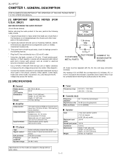
...chassis (antenna, metal cabinet, screw heads, knobs and control shafts, escutcheon, etc.) and measure the AC voltage drop across the resistor. XL-HP737 AXSMECeLuaHrdH-vrHkiAioPcePe7tP73M3T77aEnuRal1. Inspect all protective devices such as conduit or electrical ground connected to earth ground. * Use a VTVM or VOM with the... reversed. GENERAL DESCRIPTION FOR A COMPLETE DESCRIPTION OF THE OPERATION OF THIS UNIT, PLEASE REFER TO THE OPERATION MANUAL. [1] IMPORTANT SERVICE NOTES (FOR U.S.A. Any reading of 0.3 volt RMS (this model are subject to change without prior notice. 1 - 1
...chassis (antenna, metal cabinet, screw heads, knobs and control shafts, escutcheon, etc.) and measure the AC voltage drop across the resistor. XL-HP737 AXSMECeLuaHrdH-vrHkiAioPcePe7tP73M3T77aEnuRal1. Inspect all protective devices such as conduit or electrical ground connected to earth ground. * Use a VTVM or VOM with the... reversed. GENERAL DESCRIPTION FOR A COMPLETE DESCRIPTION OF THE OPERATION OF THIS UNIT, PLEASE REFER TO THE OPERATION MANUAL. [1] IMPORTANT SERVICE NOTES (FOR U.S.A. Any reading of 0.3 volt RMS (this model are subject to change without prior notice. 1 - 1
Service Manual
Page 7
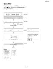
XL-HP737 2 - 3 Do normal play. FLAT X-BASS - When these following key is using manual. then, press the CD button to page 2-4 key input. STOP explanation: a) Focus off set = "FOF_XXXX" b)Tracking off set = "TOF_XXXX" c)Tracking balance = "TBAL_XX" d)Tracking Gain = "TGAN_XX" f) ...
XL-HP737 2 - 3 Do normal play. FLAT X-BASS - When these following key is using manual. then, press the CD button to page 2-4 key input. STOP explanation: a) Focus off set = "FOF_XXXX" b)Tracking off set = "TOF_XXXX" c)Tracking balance = "TBAL_XX" d)Tracking Gain = "TGAN_XX" f) ...
Service Manual
Page 67
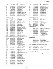
...Decoration Panel,Front B AH Panel,Cassette Cover AF Holder,Cassette AD Badge,SHARP AB Window,Cassette AD Panel,FL Display AD Indicator,Volume Knob AP ...HDECQ1110AWSA J LX-JZ0022AFFD J BC Front Panel Ass'y -- Tape Mechanism PWB Ass'y AZ Clutch Ass'y Block -- XL-HP737 NO. PARTS CODE PRICE RANK DESCRIPTION 149 150 151 152 801 802 803 804 M1 M2 SW1 SW2 SW3 SW4...TINSEA016AWZZ J TINSZA016AWZZ J AD FM Antenna AG AM Loop Antenna AS Remote Control AE Battery Lid,Remote Control AF Operation Manual AD Quick Guide P.W.B. ASSEMBLY (Not Replacement Item) 1 PWB-A1~3 PWB-B1~4 PWB-C PWB-D PWB-E PWB-F...
...Decoration Panel,Front B AH Panel,Cassette Cover AF Holder,Cassette AD Badge,SHARP AB Window,Cassette AD Panel,FL Display AD Indicator,Volume Knob AP ...HDECQ1110AWSA J LX-JZ0022AFFD J BC Front Panel Ass'y -- Tape Mechanism PWB Ass'y AZ Clutch Ass'y Block -- XL-HP737 NO. PARTS CODE PRICE RANK DESCRIPTION 149 150 151 152 801 802 803 804 M1 M2 SW1 SW2 SW3 SW4...TINSEA016AWZZ J TINSZA016AWZZ J AD FM Antenna AG AM Loop Antenna AS Remote Control AE Battery Lid,Remote Control AF Operation Manual AD Quick Guide P.W.B. ASSEMBLY (Not Replacement Item) 1 PWB-A1~3 PWB-B1~4 PWB-C PWB-D PWB-E PWB-F...
Service Manual
Page 72
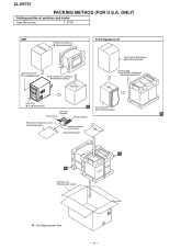
ONLY) Setting position of switches and knobs Tape Mechanism STOP UNIT Polyethylene Bag,Unit SSAKH0094AWZZ Label,Energy Star TLABZ0593AWZZ Packing Add.,Unit,Left/Right SPAKAA012AWZZ Bottom Front Speaker(L/R) Polyethylene Bag,Speaker SSAKH0101AWZZ Packing,Add., Front Speaker,Top/Bottom SPAKAA028AWZZ Label,Pop TLABZA034AWZZ A Sheet,Speaker AM Loop SPAKZA013AWZZ Antenna B FM Antenna Remote Control Polyethylene Bag,Accessories 92LBAG1460C1 Operation Manual Quick Guide B A Packing Case SPAKCA017AWZZ : Not Replacement Item - 11 - XL-HP737 PACKING METHOD (FOR U.S.A.
ONLY) Setting position of switches and knobs Tape Mechanism STOP UNIT Polyethylene Bag,Unit SSAKH0094AWZZ Label,Energy Star TLABZ0593AWZZ Packing Add.,Unit,Left/Right SPAKAA012AWZZ Bottom Front Speaker(L/R) Polyethylene Bag,Speaker SSAKH0101AWZZ Packing,Add., Front Speaker,Top/Bottom SPAKAA028AWZZ Label,Pop TLABZA034AWZZ A Sheet,Speaker AM Loop SPAKZA013AWZZ Antenna B FM Antenna Remote Control Polyethylene Bag,Accessories 92LBAG1460C1 Operation Manual Quick Guide B A Packing Case SPAKCA017AWZZ : Not Replacement Item - 11 - XL-HP737 PACKING METHOD (FOR U.S.A.


