

Service Manual
Page 1
... be used . 20MR10 SER VICE MANUAL S11O220MR10 COLOR TELEVISION Chassis No. SHARP CORPORA TION This documenthas been publishedto be used for after sales service only. 1 The contents are subject to change without notice. CONTENTS Page ELECTRICAL SPECIFICA TIONS ...1 IMPORTANT SER VICE SAFETY PRECAUTION 2 LOCATION OF USER'S CONTROL ...4 INSTALLATION AND SER VICE INSTRUCTIONS 5 CHASSIS LAYOUT ...11 BLOCK DIAGRAM ...12 SCHEMATIC DIAGRAMS ...13 PRINTED WIRING BOARD ASSEMBLIES 20 REPLACEMENT PARTS LIST...
... be used . 20MR10 SER VICE MANUAL S11O220MR10 COLOR TELEVISION Chassis No. SHARP CORPORA TION This documenthas been publishedto be used for after sales service only. 1 The contents are subject to change without notice. CONTENTS Page ELECTRICAL SPECIFICA TIONS ...1 IMPORTANT SER VICE SAFETY PRECAUTION 2 LOCATION OF USER'S CONTROL ...4 INSTALLATION AND SER VICE INSTRUCTIONS 5 CHASSIS LAYOUT ...11 BLOCK DIAGRAM ...12 SCHEMATIC DIAGRAMS ...13 PRINTED WIRING BOARD ASSEMBLIES 20 REPLACEMENT PARTS LIST...
Service Manual
Page 2
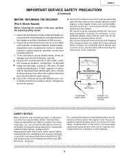
... calibration of the picture tube or high voltage circuitry and; also, under certain conditions, may cause a failure of this chassis. 4A 125V CAUTION: FOR CONTINUED PROTECTION AGAINST A RISK OF FIRE, REPLACE ONLY WITH SAME TYPE 4A125V FUSE. When the high voltage regulator is operating properly there is necessary to be checked periodically. 3. 20MR10 IMPORTANT SERVICE SAFETY PRECAUTION Service work...
... calibration of the picture tube or high voltage circuitry and; also, under certain conditions, may cause a failure of this chassis. 4A 125V CAUTION: FOR CONTINUED PROTECTION AGAINST A RISK OF FIRE, REPLACE ONLY WITH SAME TYPE 4A125V FUSE. When the high voltage regulator is operating properly there is necessary to be checked periodically. 3. 20MR10 IMPORTANT SERVICE SAFETY PRECAUTION Service work...
Service Manual
Page 3
... leads are identified by using replacement components rated for this manual; Replacement parts which do not have the same safety characteristics as the factory recommended replacement parts shown in this service manual, may create shock, fire, X-radiation or other metal parts in the following safety checks. 1. " and shaded areas in the Replacement Parts Lists and Schematic Diagrams. For continued protection, replacement parts must be used in television recevers have these check...
... leads are identified by using replacement components rated for this manual; Replacement parts which do not have the same safety characteristics as the factory recommended replacement parts shown in this service manual, may create shock, fire, X-radiation or other metal parts in the following safety checks. 1. " and shaded areas in the Replacement Parts Lists and Schematic Diagrams. For continued protection, replacement parts must be used in television recevers have these check...
Service Manual
Page 4
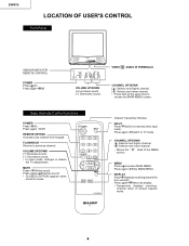
...AUDIO MENU POWER - Press again Off. MUTE Press Mutes sound. 20MR10 LOCATION OF USER'S CONTROL Front Panel SENSOR AREA FOR REMOTE CONTROL POWER Press On. VOLUME UP/DOWN (+) Increases sound. (-) Decreases sound. • In menu mode, changes or selects the TV adjustments. Press again Switch to external video input mode. Press again Exits MAIN MENU. Basic Remote Control Functions POWER Press On. G1339SB TV Infrared Transmitter Window INPUT Press Switch to TV mode. V OL + CH MENU VOLUME UP/DOWN (+) Increases sound. (-) Decreases sound. REMOTE KEYPAD Accesses any channel...
...AUDIO MENU POWER - Press again Off. MUTE Press Mutes sound. 20MR10 LOCATION OF USER'S CONTROL Front Panel SENSOR AREA FOR REMOTE CONTROL POWER Press On. VOLUME UP/DOWN (+) Increases sound. (-) Decreases sound. • In menu mode, changes or selects the TV adjustments. Press again Switch to external video input mode. Press again Exits MAIN MENU. Basic Remote Control Functions POWER Press On. G1339SB TV Infrared Transmitter Window INPUT Press Switch to TV mode. V OL + CH MENU VOLUME UP/DOWN (+) Increases sound. (-) Decreases sound. REMOTE KEYPAD Accesses any channel...
Service Manual
Page 5
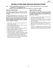
... by a 4.0A fuse (F701), mounted on PWB-A, wired into one side of picture tube. 2. Apply external 27.2V DC at zero beam). If the operation of f. 6. 20MR10 INSTALLATION AND SER VICE INSTRUCTIONS Note: (1) When performing any adjustments to resistor controls and transformers use non-metallic screwdrivers or TV alignment tools. (2) Before performing adjustments, the TV set is operating within safe and efficient design...
... by a 4.0A fuse (F701), mounted on PWB-A, wired into one side of picture tube. 2. Apply external 27.2V DC at zero beam). If the operation of f. 6. 20MR10 INSTALLATION AND SER VICE INSTRUCTIONS Note: (1) When performing any adjustments to resistor controls and transformers use non-metallic screwdrivers or TV alignment tools. (2) Before performing adjustments, the TV set is operating within safe and efficient design...
Service Manual
Page 6
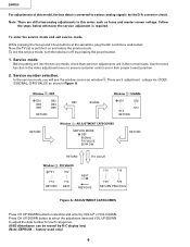
... a few analog adjustments in the normal mode. factory used only) 6 Service mode. Service number selection. Note: There are 3 adjustment categories 2 DEF, 3 SIGNAL, 4 FIX VALUE as window 1 . Press CH UP/DOWN button to select the adjustment item and VOL UP/DOWN to ensure customer control are in this model, the bus data is converted to various analog signals by VOL UP or VOL DOWN. Now, the TV set is required. Use the reset function...
... a few analog adjustments in the normal mode. factory used only) 6 Service mode. Service number selection. Note: There are 3 adjustment categories 2 DEF, 3 SIGNAL, 4 FIX VALUE as window 1 . Press CH UP/DOWN button to select the adjustment item and VOL UP/DOWN to ensure customer control are in this model, the bus data is converted to various analog signals by VOL UP or VOL DOWN. Now, the TV set is required. Use the reset function...

Service Manual
Page 7
...-7F 40 00-7F 5A 00-7F 40 00-7F 40 00-7F 40 ADJUSTMENT CONTENTS "01":Y-MUTE, "02":V-STOP&Y-MUTE "03":Activate color killer Must be "0C" SIGNAL Table - C 7 20MR10 Below are the ranges and initial values for each adjustment and in each corresponding values. A DATA INITIAL VALUE B0 04 23 00 19 00... F13 F14 F15 F16 F17 F18 F19 F20 F21 F22 F23 F24 F25 F26 ADJUST ITEM OPTION 1 OPTION 2 E-SAVE TUNER SETUP R-TONE RD R-TONE BD B-TONE RD B-TONE BD FM LEVEL AFC GAIN G DRIVE FBT BLK SW V COMP OSD CONT SHARPNESS FLT SYS KILLER OP Y PRI CORING DC REST BS START BS GAIN ABL...
...-7F 40 00-7F 5A 00-7F 40 00-7F 40 00-7F 40 ADJUSTMENT CONTENTS "01":Y-MUTE, "02":V-STOP&Y-MUTE "03":Activate color killer Must be "0C" SIGNAL Table - C 7 20MR10 Below are the ranges and initial values for each adjustment and in each corresponding values. A DATA INITIAL VALUE B0 04 23 00 19 00... F13 F14 F15 F16 F17 F18 F19 F20 F21 F22 F23 F24 F25 F26 ADJUST ITEM OPTION 1 OPTION 2 E-SAVE TUNER SETUP R-TONE RD R-TONE BD B-TONE RD B-TONE BD FM LEVEL AFC GAIN G DRIVE FBT BLK SW V COMP OSD CONT SHARPNESS FLT SYS KILLER OP Y PRI CORING DC REST BS START BS GAIN ABL...
Service Manual
Page 8
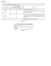
... - E 8 20MR10 Holding down both the Vol-up /Ch-down buttons on the TV set in IC2102 (IC2101). Table - Adjust items related to compensate for more than 2 seconds will automatically write the above initial values into IC2102 (IC2101). D If using IC2101 If using IC2102 R2101 R2102 R2103 -- PART REPLACED ADJUSTMENT NECESSAR Y UNNECESSAR Y NOTES IC2001 X Data is stored in the service mode for...
... - E 8 20MR10 Holding down both the Vol-up /Ch-down buttons on the TV set in IC2102 (IC2101). Table - Adjust items related to compensate for more than 2 seconds will automatically write the above initial values into IC2102 (IC2101). D If using IC2101 If using IC2102 R2101 R2102 R2103 -- PART REPLACED ADJUSTMENT NECESSAR Y UNNECESSAR Y NOTES IC2001 X Data is stored in the service mode for...
Service Manual
Page 9
... step, if you selected a B/W picture or monoscope. 3. Adjust the data value to obtain a normal contrast level. Enter the service mode and select the service adjustment "S11". 4. Make sure the customer color control is set the color level to center position. 3. 20MR10 SER VICE ADJUSTMENT RF AGC Adjustment 1. Note: You have to exit the service mode first to select another channel to turn off the luminance signal (Y-mute). 5. Set the data value to...
... step, if you selected a B/W picture or monoscope. 3. Adjust the data value to obtain a normal contrast level. Enter the service mode and select the service adjustment "S11". 4. Make sure the customer color control is set the color level to center position. 3. 20MR10 SER VICE ADJUSTMENT RF AGC Adjustment 1. Note: You have to exit the service mode first to select another channel to turn off the luminance signal (Y-mute). 5. Set the data value to...
Service Manual
Page 10
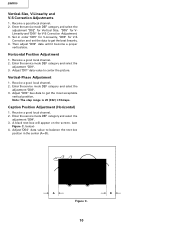
... channel. 2. Set in order "D05" for V-Linearity, "D06" for V-S Correction Adjustment. 3. Enter the service mode DEF category and select the adjustment "D03". 3. Caption Position Adjustment (Horizontal) 1. below) 4. Adjust "D04" data value to get the most acceptable vertical position. Adjust "D03" bus data to center the picture. A B Figure C. 10 Receive a good local channel. 2. Adjust "D01" data value to get the best linearity. 4. 20MR10 Vertical-Size, V-Linearity and V-S Correction Adjustments...
... channel. 2. Set in order "D05" for V-Linearity, "D06" for V-S Correction Adjustment. 3. Enter the service mode DEF category and select the adjustment "D03". 3. Caption Position Adjustment (Horizontal) 1. below) 4. Adjust "D04" data value to get the most acceptable vertical position. Adjust "D03" bus data to center the picture. A B Figure C. 10 Receive a good local channel. 2. Adjust "D01" data value to get the best linearity. 4. 20MR10 Vertical-Size, V-Linearity and V-S Correction Adjustments...
Service Manual
Page 13
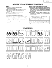
... otherwise noted. 3. WAVEFORM MEASUREMENT CONDITIONS: 1. Photographs taken on the tint, color level and picture control. 2. MARK= X-RAY RELATED PARTS. All capacitors are measured with 1000µ V B & W or Color signal. AND SHADED ( ) COMPONENTS = SAFETY RELATED PARTS. VOLTAGE MEASUREMENTCONDITIONS: 1. The unit of the picture tube depend on a standard gated color bar signal, the tint setting adjusted for product improvement without prior notice. 20MR10 DESCRIPTION OF SCHEMATIC DIAGRAM NOTES: 1.
... otherwise noted. 3. WAVEFORM MEASUREMENT CONDITIONS: 1. Photographs taken on the tint, color level and picture control. 2. MARK= X-RAY RELATED PARTS. All capacitors are measured with 1000µ V B & W or Color signal. AND SHADED ( ) COMPONENTS = SAFETY RELATED PARTS. VOLTAGE MEASUREMENTCONDITIONS: 1. The unit of the picture tube depend on a standard gated color bar signal, the tint setting adjusted for product improvement without prior notice. 20MR10 DESCRIPTION OF SCHEMATIC DIAGRAM NOTES: 1.
Service Manual
Page 16
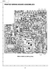
20MR10 PRINTED WIRING BOARD ASSEMBLIES H G F E D C B PWB-A: MAIN Unit (Wiring Side) A 1 2 3 4 5 6 17
20MR10 PRINTED WIRING BOARD ASSEMBLIES H G F E D C B PWB-A: MAIN Unit (Wiring Side) A 1 2 3 4 5 6 17
Service Manual
Page 19
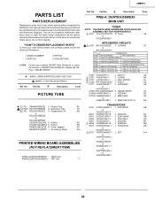
... correctly, please furnish the following informations. 1. MODEL NUMBER 3. PART NO. 2. DESCRIPTION in this service manual may create shock, fire or other hazards. RAY RELATED PARTS Ref. Part No. NO. 4. No. Part No. 20MR10 Ref. No. electrical components having such features are identified by ! "HOW TO ORDER REPLACEMENT PARTS" To have your nearest SHARP Parts Distributor to order. Description Code PICTURE TUBE ! IC201 RH-iX3354CEZZ J LA76843 AT...
... correctly, please furnish the following informations. 1. MODEL NUMBER 3. PART NO. 2. DESCRIPTION in this service manual may create shock, fire or other hazards. RAY RELATED PARTS Ref. Part No. NO. 4. No. Part No. 20MR10 Ref. No. electrical components having such features are identified by ! "HOW TO ORDER REPLACEMENT PARTS" To have your nearest SHARP Parts Distributor to order. Description Code PICTURE TUBE ! IC201 RH-iX3354CEZZ J LA76843 AT...
Service Manual
Page 23
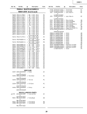
.... J 330 1/8W Carbon SWITCHES S2501 QSW-K0202PEZZ J Power or QSW-K0079GEZZ S2502 QSW-...PARTS ! Description Code FH701 QFSHD1013CEZZ J Fuse Holder AC FH702 QFSHD1014CEZZ J Fuse Holder AC J903 QJAKE0205CE09 J Jack, Audio-In AD or QJAKE0159CEZZ J905 QJAKE0205CE04 J Jack, Video-In AD or QJAKE0158CEZZ P302 QPLGN0261CEZZ J Plug, 2-pin(S) AB P401 QPLGN0561CEZZ J Plug, 5-pin(GBN) AB P601 QPLGN0660CEZZ J Plug, 6-pin(K) AC P651 QPLGN0361CEZZ J Plug, 3-pin(TP651-3) AB P701 QPLGN0260CEZZ J Plug, 2-pin(M) AC P751 QPLGN0461CEZZ J Plug... Q701 AD LX-BZ3100CEFD J Screw AA 24 No. J 5....
.... J 330 1/8W Carbon SWITCHES S2501 QSW-K0202PEZZ J Power or QSW-K0079GEZZ S2502 QSW-...PARTS ! Description Code FH701 QFSHD1013CEZZ J Fuse Holder AC FH702 QFSHD1014CEZZ J Fuse Holder AC J903 QJAKE0205CE09 J Jack, Audio-In AD or QJAKE0159CEZZ J905 QJAKE0205CE04 J Jack, Video-In AD or QJAKE0158CEZZ P302 QPLGN0261CEZZ J Plug, 2-pin(S) AB P401 QPLGN0561CEZZ J Plug, 5-pin(GBN) AB P601 QPLGN0660CEZZ J Plug, 6-pin(K) AC P651 QPLGN0361CEZZ J Plug, 3-pin(TP651-3) AB P701 QPLGN0260CEZZ J Plug, 2-pin(M) AC P751 QPLGN0461CEZZ J Plug... Q701 AD LX-BZ3100CEFD J Screw AA 24 No. J 5....
Service Manual
Page 24
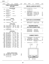
... VRS-CY1JF561J J 560 1/16W M-Ox. 20MR10 Ref. ACC701 QACCD3064CESA J AC Cord AM or QACCD3090CESA or QACCD3060CESA SP1 VSP0080PBP7YA X Speaker, 32 ohm AL QCNW-2111PEZZ J Connecting Cord AF QCNW-2112PEZZ J Connecting Cord AF QCNW-2160PEZZ J Connecting Cord AG TCAUS3000GJZZ X Caution Card AB TLABM0003GJZZ X Label AB SUPPLIED ACCESORRIES RRMCG1339CESB X Infrared R/C Unit AQ TiNS-7371GJZZ X Operation Manual AG PACKING PARTS (NOT REPLACEMENT ITEM) SPAKC0210GJZZ - R865 VRS-VU3AE123J...
... VRS-CY1JF561J J 560 1/16W M-Ox. 20MR10 Ref. ACC701 QACCD3064CESA J AC Cord AM or QACCD3090CESA or QACCD3060CESA SP1 VSP0080PBP7YA X Speaker, 32 ohm AL QCNW-2111PEZZ J Connecting Cord AF QCNW-2112PEZZ J Connecting Cord AF QCNW-2160PEZZ J Connecting Cord AG TCAUS3000GJZZ X Caution Card AB TLABM0003GJZZ X Label AB SUPPLIED ACCESORRIES RRMCG1339CESB X Infrared R/C Unit AQ TiNS-7371GJZZ X Operation Manual AG PACKING PARTS (NOT REPLACEMENT ITEM) SPAKC0210GJZZ - R865 VRS-VU3AE123J...
Service Manual
Page 25
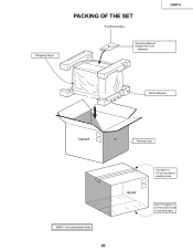
Part No. Polyethylene Bag 20MR10 Description Code Operation Manual Infrared R/C Unit Batteries Buffer Material FRONT Packing Case MARK : Not replacement items. 26 REAR Use tape to fix the bottom side of packing case. Ref. Use 10 staples to fix the top side of packing case. No. Wrapping Paper PACKING OF THE SET Description Code Ref. No. Part No.
Part No. Polyethylene Bag 20MR10 Description Code Operation Manual Infrared R/C Unit Batteries Buffer Material FRONT Packing Case MARK : Not replacement items. 26 REAR Use tape to fix the bottom side of packing case. Ref. Use 10 staples to fix the top side of packing case. No. Wrapping Paper PACKING OF THE SET Description Code Ref. No. Part No.
Service Manual
Page 26
KG SHARP ELECTRONICA MEXICO S.A. Description Code Ref. DE C.V. No. No. Description Code COPYRIGHT © 2001 BY SHARP CORPORATION ALL RIGHTS RESERVED. SHARP No. 3510 Parque Industrial Rosarito, Playas de Rosarito, B. C. 22710 30 Part No. No part of this publication may be reproduced, stored in a retrieval system, or transmitted in Japan MI. Blvd. D SEM P SEMEX TQ1071-S Jun. 2001 Printed in any form or by any means, electronic, mechanical, photocopying, recording, or otherwise, without prior written permission of the publisher. Part No. 20MR10 Ref.
KG SHARP ELECTRONICA MEXICO S.A. Description Code Ref. DE C.V. No. No. Description Code COPYRIGHT © 2001 BY SHARP CORPORATION ALL RIGHTS RESERVED. SHARP No. 3510 Parque Industrial Rosarito, Playas de Rosarito, B. C. 22710 30 Part No. No part of this publication may be reproduced, stored in a retrieval system, or transmitted in Japan MI. Blvd. D SEM P SEMEX TQ1071-S Jun. 2001 Printed in any form or by any means, electronic, mechanical, photocopying, recording, or otherwise, without prior written permission of the publisher. Part No. 20MR10 Ref.


