
Service Manual
Page 2
...has two ground systems whichare separated by connecting a 10k ohm resistor in series withan insulated wire (such as specified in current solid state TV receivers is no modification of desirable levels. 4. The only potential source of X-ray in the "High Voltage Check" instructions. The ... of this chassis. 4A 125V CAUTION: FOR CONTINUED PROTECTION AGAINST A RISK OF FIRE, REPLACE ONLY WITH SAME TYPE 4A125V FUSE. 20MR10 IMPORTANT SERVICE SAFETY PRECAUTION Service work should be tested while monitoring the high voltage witha meter to be certain that the high voltage does...
...has two ground systems whichare separated by connecting a 10k ohm resistor in series withan insulated wire (such as specified in current solid state TV receivers is no modification of desirable levels. 4. The only potential source of X-ray in the "High Voltage Check" instructions. The ... of this chassis. 4A 125V CAUTION: FOR CONTINUED PROTECTION AGAINST A RISK OF FIRE, REPLACE ONLY WITH SAME TYPE 4A125V FUSE. 20MR10 IMPORTANT SERVICE SAFETY PRECAUTION Service work should be tested while monitoring the high voltage witha meter to be certain that the high voltage does...
Service Manual
Page 4
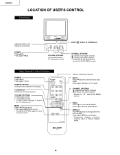
.... Press again Removes display. • Temporarily displays receiving channel when in Closed Caption mode. 4 20MR10 LOCATION OF USER'S CONTROL Front Panel SENSOR AREA FOR REMOTE CONTROL POWER Press On. G1339SB TV Infrared Transmitter Window INPUT Press Switch to TV mode. MENU Press Accesses MAIN MENU. VOLUME UP/DOWN (+) Increases sound. (-) Decreases sound. •...
.... Press again Removes display. • Temporarily displays receiving channel when in Closed Caption mode. 4 20MR10 LOCATION OF USER'S CONTROL Front Panel SENSOR AREA FOR REMOTE CONTROL POWER Press On. G1339SB TV Infrared Transmitter Window INPUT Press Switch to TV mode. MENU Press Accesses MAIN MENU. VOLUME UP/DOWN (+) Increases sound. (-) Decreases sound. •...
Service Manual
Page 5
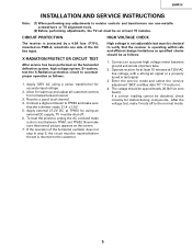
...to ascertain proper operation as follows: 1. Operate receiver for at least 15 minutes at zero beam). Apply 120V AC using an external DC supply, TV must be shut of the horizontal oscillator does not stop in test signal. 3. Apply external 27.2V DC at least 15 minutes. Connect an accurate...PWB-A, wired into one side of picture tube. 2. After the voltage test, make a short circuit between ground and anode of the AC line input. 20MR10 INSTALLATION AND SER VICE INSTRUCTIONS Note: (1) When performing any adjustments to resistor controls and transformers use non-metallic screwdrivers or...
...to ascertain proper operation as follows: 1. Operate receiver for at least 15 minutes at zero beam). Apply 120V AC using an external DC supply, TV must be shut of the horizontal oscillator does not stop in test signal. 3. Apply external 27.2V DC at least 15 minutes. Connect an accurate...PWB-A, wired into one side of picture tube. 2. After the voltage test, make a short circuit between ground and anode of the AC line input. 20MR10 INSTALLATION AND SER VICE INSTRUCTIONS Note: (1) When performing any adjustments to resistor controls and transformers use non-metallic screwdrivers or...
Service Manual
Page 6
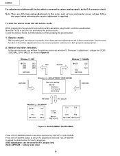
... F26 RETURN PREVIOUS Figure A: ADJUSTMENT CATEGORIES Press CH UP/DOWN buttonfor selectionand enter by pressing the power button. 1. Note: There are in Figure A. Now, the TV set is required. In the service mode, you will see the window screen as window 1 . Follow the steps below whenever the service adjusment is switched... can be erased by the D/A converter circuit. factory used only) 6 To exit the service mode, turn the television off by VOL UP or VOL DOWN. 20MR10 For adjustments of this series such as focus and master screen voltage.
... F26 RETURN PREVIOUS Figure A: ADJUSTMENT CATEGORIES Press CH UP/DOWN buttonfor selectionand enter by pressing the power button. 1. Note: There are in Figure A. Now, the TV set is required. In the service mode, you will see the window screen as window 1 . Follow the steps below whenever the service adjusment is switched... can be erased by the D/A converter circuit. factory used only) 6 To exit the service mode, turn the television off by VOL UP or VOL DOWN. 20MR10 For adjustments of this series such as focus and master screen voltage.
Service Manual
Page 8
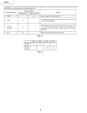
20MR10 Holding down both the Vol-up /Ch-down buttons on the TV set in IC2102 (IC2101). Adjust items related to compensate for more than 2 seconds will automatically write the above initial values into IC2102 (IC2101). R2104 ...-- IC201 X The adjustmentis needed to picture tube only. IC2102 X (IC2101) CR T X Holding down both the Vol-up /Ch-down buttons on the TV set at service mode for characteristics of parts includingIC201. Table - PART REPLACED ADJUSTMENT NECESSAR Y UNNECESSAR Y NOTES IC2001 X Data is stored in the service mode for...
20MR10 Holding down both the Vol-up /Ch-down buttons on the TV set in IC2102 (IC2101). Adjust items related to compensate for more than 2 seconds will automatically write the above initial values into IC2102 (IC2101). R2104 ...-- IC201 X The adjustmentis needed to picture tube only. IC2102 X (IC2101) CR T X Holding down both the Vol-up /Ch-down buttons on the TV set at service mode for characteristics of parts includingIC201. Table - PART REPLACED ADJUSTMENT NECESSAR Y UNNECESSAR Y NOTES IC2001 X Data is stored in the service mode for...
Service Manual
Page 9
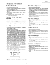
...the luminance signal (Y-mute). 5. Enter the service mode and select the service adjustment "S12". 4. Enter the service mode and select the service adjustment "S13". 4. 20MR10 SER VICE ADJUSTMENT RF AGC Adjustment 1. Enter the service mode and select the service adjustment "S11". 4. Set also the "S05/S06/S07" data to obtain...Receive a good local channel. 2. Sub-Color Adjustment 1. Enter the service mode signal category and select the service adjustment "S01". 3. Receive a good local channel. 2. V ideo Level (TV Det Video Level) Adjustment 1. Screen Adjustment 1.
...the luminance signal (Y-mute). 5. Enter the service mode and select the service adjustment "S12". 4. Enter the service mode and select the service adjustment "S13". 4. 20MR10 SER VICE ADJUSTMENT RF AGC Adjustment 1. Enter the service mode and select the service adjustment "S11". 4. Set also the "S05/S06/S07" data to obtain...Receive a good local channel. 2. Sub-Color Adjustment 1. Enter the service mode signal category and select the service adjustment "S01". 3. Receive a good local channel. 2. V ideo Level (TV Det Video Level) Adjustment 1. Screen Adjustment 1.


