Owner's Manual
Page 37
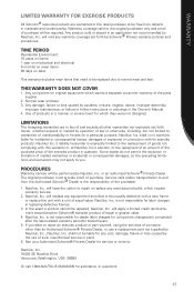
...otherwise, including, but not limited to, warranties of merchantability or fitness for any cost, damage, failure or loss caused by Schwinn® Fitness warranty policies and procedures. Service calls and/or transportation to you elect to repair an exercise product or part ...of someone other warranties not expressly set forth by the use a replacement part not supplied by accident, misuse, neglect, abuse, improper assembly, improper maintenance, or failure to follow instructions or warnings in a manner or environment for component changeovers completed after the labor-related ...
...otherwise, including, but not limited to, warranties of merchantability or fitness for any cost, damage, failure or loss caused by Schwinn® Fitness warranty policies and procedures. Service calls and/or transportation to you elect to repair an exercise product or part ...of someone other warranties not expressly set forth by the use a replacement part not supplied by accident, misuse, neglect, abuse, improper assembly, improper maintenance, or failure to follow instructions or warnings in a manner or environment for component changeovers completed after the labor-related ...

Assembly Manual
Page 3
CONTENTS Table of Contents Hardware 2 Exploded View 4 Parts List 5 Assembly Instructions 6 Important Contact Numbers 21 1
CONTENTS Table of Contents Hardware 2 Exploded View 4 Parts List 5 Assembly Instructions 6 Important Contact Numbers 21 1
Assembly Manual
Page 4
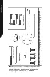
If you have damaged components, please contact Schwinn at 1.800.864.1270 2 I-10 Carriage Bolt M8xP1.25x85MM (1) I-1 M8xP1.25x85mm I-4 lock nut for M8 � (1) I-2 Knob (1) I-7 Allen Bolt M8xP1.0x45mm (4) Screwdriver I-6 Screws M8x16mm Socket Wrench���� ���� HARDWARE Note: Please verify you are missing items, are short quantities, or have all correct parts and quantities before assembling unit.
If you have damaged components, please contact Schwinn at 1.800.864.1270 2 I-10 Carriage Bolt M8xP1.25x85MM (1) I-1 M8xP1.25x85mm I-4 lock nut for M8 � (1) I-2 Knob (1) I-7 Allen Bolt M8xP1.0x45mm (4) Screwdriver I-6 Screws M8x16mm Socket Wrench���� ���� HARDWARE Note: Please verify you are missing items, are short quantities, or have all correct parts and quantities before assembling unit.
Assembly Manual
Page 5
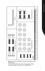
If you have damaged components, please contact Schwinn at 1.800.864.1270 3 I-7 Allen Bolt M8xP1.0x45mm (4) Allen Key���� 4) I-3 Regular Washer 8*16*2t(15) I-5 Allen Bolt M8xP1.25x16mm (5) ���� HARDWARE Note: Please verify you are missing items, are short quantities, or have all correct parts and quantities before assembling unit.
If you have damaged components, please contact Schwinn at 1.800.864.1270 3 I-7 Allen Bolt M8xP1.0x45mm (4) Allen Key���� 4) I-3 Regular Washer 8*16*2t(15) I-5 Allen Bolt M8xP1.25x16mm (5) ���� HARDWARE Note: Please verify you are missing items, are short quantities, or have all correct parts and quantities before assembling unit.

Assembly Manual
Page 8
By using these principles, you can simplify each step and thoroughly read the assembly instructions for the step. 2. To make the assembly process go faster, gather the pieces you need for each process and save yourself extra time and effort. 1. Or you can remember the ... rule, and for all bolts and nuts, turn bolts or nuts toward the right to tighten and left to starting assembly for that will aid in the assembly process . ASSEMBLY INSTRUCTIONS Basic Assembly Principles Here are a few basic tips that step prior to loosen. When attaching two pieces, gently lift and look ...
By using these principles, you can simplify each step and thoroughly read the assembly instructions for the step. 2. To make the assembly process go faster, gather the pieces you need for each process and save yourself extra time and effort. 1. Or you can remember the ... rule, and for all bolts and nuts, turn bolts or nuts toward the right to tighten and left to starting assembly for that will aid in the assembly process . ASSEMBLY INSTRUCTIONS Basic Assembly Principles Here are a few basic tips that step prior to loosen. When attaching two pieces, gently lift and look ...
Assembly Manual
Page 9
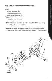
I-6) Tools: • Supplied Allen Wrench 1-1 Attach the Rear Stabilizer (G) to the rear of the Main Unit using two M8 X 16mm screws. ASSEMBLY INSTRUCTIONS Step 1 Install Front and Rear Stabilizers Parts: • Front Stabilizer (Ref. E ) • Rear Stabilizer (Ref. G ) • M8x16 Screws (Ref. I-6 G I -6). 1-2 Attach the Front Stabilizer (E) with the UP sticker and wheels toward the front of the Main Unit using two M8 X 16mm screws (I -6 E UP sticker 7
I-6) Tools: • Supplied Allen Wrench 1-1 Attach the Rear Stabilizer (G) to the rear of the Main Unit using two M8 X 16mm screws. ASSEMBLY INSTRUCTIONS Step 1 Install Front and Rear Stabilizers Parts: • Front Stabilizer (Ref. E ) • Rear Stabilizer (Ref. G ) • M8x16 Screws (Ref. I-6 G I -6). 1-2 Attach the Front Stabilizer (E) with the UP sticker and wheels toward the front of the Main Unit using two M8 X 16mm screws (I -6 E UP sticker 7
Assembly Manual
Page 10
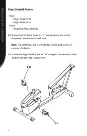
ASSEMBLY INSTRUCTIONS Step 2 Install Pedals Parts: • Right Pedal (F-R) • Right Pedal (F-L) Tools: • Supplied Pedal Wrench 2-1 Screw the Left Pedal ( has an "L" stamped into the end of the pedal ) into the Left Crank Arm. Note: The Left Pedal has a left handed thread and screws in counter clockwise. 2-2 Screw the Right Pedal ( has an "R "stamped into the end of the pedal ) into the Right Crank Arm. F-R F-L 8
ASSEMBLY INSTRUCTIONS Step 2 Install Pedals Parts: • Right Pedal (F-R) • Right Pedal (F-L) Tools: • Supplied Pedal Wrench 2-1 Screw the Left Pedal ( has an "L" stamped into the end of the pedal ) into the Left Crank Arm. Note: The Left Pedal has a left handed thread and screws in counter clockwise. 2-2 Screw the Right Pedal ( has an "R "stamped into the end of the pedal ) into the Right Crank Arm. F-R F-L 8
Assembly Manual
Page 11
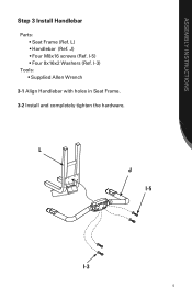
I -3) Tools: • Supplied Allen Wrench 3-1 Align Handlebar with holes in Seat Frame. 3-2 Install and completely tighten the hardware. I -5) • Four 8x16x2 Washers (Ref. J) • Four M8x16 screws (Ref. L) • Handlebar (Ref. L J I-5 I-3 9 ASSEMBLY INSTRUCTIONS Step 3 Install Handlebar Parts: • Seat Frame (Ref.
I -3) Tools: • Supplied Allen Wrench 3-1 Align Handlebar with holes in Seat Frame. 3-2 Install and completely tighten the hardware. I -5) • Four 8x16x2 Washers (Ref. J) • Four M8x16 screws (Ref. L) • Handlebar (Ref. L J I-5 I-3 9 ASSEMBLY INSTRUCTIONS Step 3 Install Handlebar Parts: • Seat Frame (Ref.
Assembly Manual
Page 12
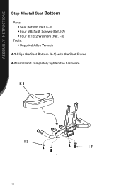
K-1) • Four M8x1x45 Screws (Ref. K-1 I-3 I -7) • Four 8x16x2 Washers (Ref. I -7 10 I-3) Tools: • Supplied Allen Wrench 4-1 Align the Seat Bottom (K-1) with the Seat Frame. 4-2 Install and completely tighten the hardware. ASSEMBLY INSTRUCTIONS Step 4 Install Seat Bottom Parts: • Seat Bottom (Ref.
K-1) • Four M8x1x45 Screws (Ref. K-1 I-3 I -7) • Four 8x16x2 Washers (Ref. I -7 10 I-3) Tools: • Supplied Allen Wrench 4-1 Align the Seat Bottom (K-1) with the Seat Frame. 4-2 Install and completely tighten the hardware. ASSEMBLY INSTRUCTIONS Step 4 Install Seat Bottom Parts: • Seat Bottom (Ref.
Assembly Manual
Page 13
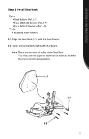
You may use the upper or lower set of holes in the Seat Back. Note: There are two sets of holes to find the the most comfortable position. L-1 I-7 I -3) Tools: • Supplied Allen Wrench 5-1 Align the Seat Back (L-1) with the Seat Frame. 5-2 Install and completely tighten the hardware. L-1) • Four M8x1x45 Screws (Ref. I -3 11 I-7) • Four 8x16x2 Washers (Ref. ASSEMBLY INSTRUCTIONS Step 5 Install Seat back Parts: • Seat Bottom (Ref.
You may use the upper or lower set of holes in the Seat Back. Note: There are two sets of holes to find the the most comfortable position. L-1 I-7 I -3) Tools: • Supplied Allen Wrench 5-1 Align the Seat Back (L-1) with the Seat Frame. 5-2 Install and completely tighten the hardware. L-1) • Four M8x1x45 Screws (Ref. I -3 11 I-7) • Four 8x16x2 Washers (Ref. ASSEMBLY INSTRUCTIONS Step 5 Install Seat back Parts: • Seat Bottom (Ref.
Assembly Manual
Page 14
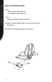
ASSEMBLY INSTRUCTIONS Step 6 Install Bottle Holder Parts: • Water Bottle Holder (Ref. K-2) • Four M5x16 Screws (Ref. I -8) Tools: • Supplied Phillips Head Screwdriver 6-1 Align the Water Bottle Holder under the left side of the Seat Bottom. 6-2 Install and completely tighten the hardware. I -8 K-2 12
ASSEMBLY INSTRUCTIONS Step 6 Install Bottle Holder Parts: • Water Bottle Holder (Ref. K-2) • Four M5x16 Screws (Ref. I -8) Tools: • Supplied Phillips Head Screwdriver 6-1 Align the Water Bottle Holder under the left side of the Seat Bottom. 6-2 Install and completely tighten the hardware. I -8 K-2 12
Assembly Manual
Page 15
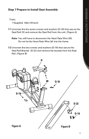
Do not let the Heart Rate Wire fall into the frame. 7-2 Unscrew the two screws and washers (D-18) that secure the Seat Rail (H) and remove the Seat Rail from the unit. (Figure A) Note: You will have to Install Seat Assembly Tools: • Supplied Allen Wrench 7-1 Unscrew the the seven screws and washers (D-18) that secure the Seat Rail Bracket (D-22) and remove the bracket from the Seat Rail. (Figure B) H D-18 Figure A M D-18 D-22 D-18 Figure B 13 ASSEMBLY INSTRUCTIONS Step 7 Prepare to disconnect the Heart Rate Wire (M).
Do not let the Heart Rate Wire fall into the frame. 7-2 Unscrew the two screws and washers (D-18) that secure the Seat Rail (H) and remove the Seat Rail from the unit. (Figure A) Note: You will have to Install Seat Assembly Tools: • Supplied Allen Wrench 7-1 Unscrew the the seven screws and washers (D-18) that secure the Seat Rail Bracket (D-22) and remove the bracket from the Seat Rail. (Figure B) H D-18 Figure A M D-18 D-22 D-18 Figure B 13 ASSEMBLY INSTRUCTIONS Step 7 Prepare to disconnect the Heart Rate Wire (M).
Assembly Manual
Page 16
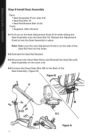
...Reinstall the Seat Rail Bracket. 8-3 Reconnect the Heart Rate Wires and Reinstall the Seat Rail with Seat Assembly on the Seat Adjustment Knob (K-3) while sliding the Seat Assembly onto the Seat Rail (H). Note: Make sure the seat Adjustment Knob is on the side of the ...Seat Assembly. (Figure B) Figure B H D-22 14 M K-3 Figure A ASSEMBLY INSTRUCTIONS Step 8 Install Seat Assembly Parts: • Seat Assembly (From step 3-6) • Seat Rail (Ref. H) • Seat Rail Bracket (Ref. D-22) Tools: •...
...Reinstall the Seat Rail Bracket. 8-3 Reconnect the Heart Rate Wires and Reinstall the Seat Rail with Seat Assembly on the Seat Adjustment Knob (K-3) while sliding the Seat Assembly onto the Seat Rail (H). Note: Make sure the seat Adjustment Knob is on the side of the ...Seat Assembly. (Figure B) Figure B H D-22 14 M K-3 Figure A ASSEMBLY INSTRUCTIONS Step 8 Install Seat Assembly Parts: • Seat Assembly (From step 3-6) • Seat Rail (Ref. H) • Seat Rail Bracket (Ref. D-22) Tools: •...
Assembly Manual
Page 17
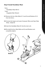
C Detail A C-2 C-1 15 ASSEMBLY INSTRUCTIONS Step 9 Install Handlebar Mast Parts: • Handlebar Mast (Ref C) Tools: • Supplied Allen Wrench 9-1 Remove the four Allen Bolts (C-1) and Curved Washers (C-2) from the frame . 9-2 Connect the Upper and Lower Computer Wires and Heart Rate Wires. (Detail A) 9-3 Insert the Handlebar Mast (C) into the main unit. 9-4 Re-install the four Allen Bolts and Curved Washers and completely tighten.
C Detail A C-2 C-1 15 ASSEMBLY INSTRUCTIONS Step 9 Install Handlebar Mast Parts: • Handlebar Mast (Ref C) Tools: • Supplied Allen Wrench 9-1 Remove the four Allen Bolts (C-1) and Curved Washers (C-2) from the frame . 9-2 Connect the Upper and Lower Computer Wires and Heart Rate Wires. (Detail A) 9-3 Insert the Handlebar Mast (C) into the main unit. 9-4 Re-install the four Allen Bolts and Curved Washers and completely tighten.
Assembly Manual
Page 18
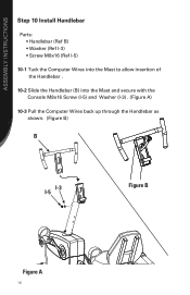
ASSEMBLY INSTRUCTIONS Step 10 Install Handlebar Parts: • Handlebar (Ref B) • Washer (Ref I-3) • Screw M8x16 (Ref I-5) 10-1 Tuck the Computer Wires into the Mast to allow insertion of the Handlebar . 10-2 Slide the Handlebar (B) into the Mast and secure with the Console M8x16 Screw (I-5) and Washer (I-3) . (Figure A) 10-3 Pull the Computer Wires back up through the Handlebar as shown. (Figure B) B I-3 I-5 Figure B Figure A 16
ASSEMBLY INSTRUCTIONS Step 10 Install Handlebar Parts: • Handlebar (Ref B) • Washer (Ref I-3) • Screw M8x16 (Ref I-5) 10-1 Tuck the Computer Wires into the Mast to allow insertion of the Handlebar . 10-2 Slide the Handlebar (B) into the Mast and secure with the Console M8x16 Screw (I-5) and Washer (I-3) . (Figure A) 10-3 Pull the Computer Wires back up through the Handlebar as shown. (Figure B) B I-3 I-5 Figure B Figure A 16
Assembly Manual
Page 19
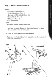
... Flat Wrenches 11-1 Align the Computer Bracket (A-1) with the holes in the Mast. (See assembled view for reference) 11-2 Install and completely tighten the hardware. ASSEMBLY INSTRUCTIONS Step 11 Install Computer Bracket Parts: • Computer Bracket (Ref. I -4 Assembled 17 Note: Use the Angle Adjust Knob to position the Computer to fit individual preferences...
... Flat Wrenches 11-1 Align the Computer Bracket (A-1) with the holes in the Mast. (See assembled view for reference) 11-2 Install and completely tighten the hardware. ASSEMBLY INSTRUCTIONS Step 11 Install Computer Bracket Parts: • Computer Bracket (Ref. I -4 Assembled 17 Note: Use the Angle Adjust Knob to position the Computer to fit individual preferences...
Assembly Manual
Page 20
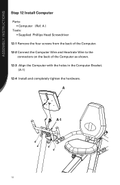
A A-1 18 A ) Tools: • Supplied Phillips Head Screwdriver 12-1 Remove the four screws from the back of the Computer. 12-2 Connect the Computer Wire and Heartrate Wire to the connectors on the back of the Computer as shown. 12-3 Align the Computer with the holes in the Computer Bracket. (A-1) 12-4 Install and completely tighten the hardware. ASSEMBLY INSTRUCTIONS Step 12 Install Computer Parts: • Computer (Ref.
A A-1 18 A ) Tools: • Supplied Phillips Head Screwdriver 12-1 Remove the four screws from the back of the Computer. 12-2 Connect the Computer Wire and Heartrate Wire to the connectors on the back of the Computer as shown. 12-3 Align the Computer with the holes in the Computer Bracket. (A-1) 12-4 Install and completely tighten the hardware. ASSEMBLY INSTRUCTIONS Step 12 Install Computer Parts: • Computer (Ref.
Assembly Manual
Page 21
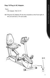
D-17 19 ASSEMBLY INSTRUCTIONS Step 13 Plug in AC Adapter Parts: • AC Adapter (Ref. D-17) 13-1 Plug the AC Adapter (P) into the recepticle on the front right of the unit and into a 110 volt outlet.
D-17 19 ASSEMBLY INSTRUCTIONS Step 13 Plug in AC Adapter Parts: • AC Adapter (Ref. D-17) 13-1 Plug the AC Adapter (P) into the recepticle on the front right of the unit and into a 110 volt outlet.

Assembly Manual
Page 22
ASSEMBLY INSTRUCTIONS Assembly is complete! Please reference the Owner's Manual for information regarding computer operation, product maintenance, Warranty information, and general fitness and exercise guidelines. 20
ASSEMBLY INSTRUCTIONS Assembly is complete! Please reference the Owner's Manual for information regarding computer operation, product maintenance, Warranty information, and general fitness and exercise guidelines. 20


