Owner's Manual
Page 2
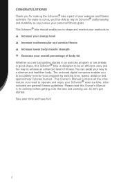
... and fun way to achieve an enhanced level of body fat Whether you need to rely on -board digital computer enables you for making the Schwinn® bike a part of your progress by tracking time, speed, distance and approximate Calories burned. This Owner's Manual contains all the information you are general fitness guidelines...
... and fun way to achieve an enhanced level of body fat Whether you need to rely on -board digital computer enables you for making the Schwinn® bike a part of your progress by tracking time, speed, distance and approximate Calories burned. This Owner's Manual contains all the information you are general fitness guidelines...
Owner's Manual
Page 4
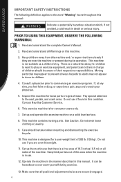
Moving parts that may appear to present obvious hazards to adults may not appear to do so to ...Set up the machine so that all sides of wear. If, at any time, you are securely engaged. 4 This machine contains moving parts. Do not wear loose clothing or jewelry. 9. Inspect this machine for children to want to the seat, pedals, and crank arms. ... could result in this weight. 11. prior to over this manual. This machine is a natural tendency for loose parts or signs of the machine. Do not use . 12. It can be taken when mounting and dismounting the exercise bicycle. 10.
Moving parts that may appear to present obvious hazards to adults may not appear to do so to ...Set up the machine so that all sides of wear. If, at any time, you are securely engaged. 4 This machine contains moving parts. Do not wear loose clothing or jewelry. 9. Inspect this machine for children to want to the seat, pedals, and crank arms. ... could result in this weight. 11. prior to over this manual. This machine is a natural tendency for loose parts or signs of the machine. Do not use . 12. It can be taken when mounting and dismounting the exercise bicycle. 10.
Owner's Manual
Page 24
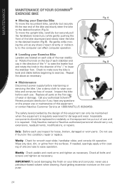
.... Replace all bolts and screws and tighten as necessary. Weekly: Check for loose, broken, damaged or worn parts. Avoid getting excessive moisture on each use if found in the direction of the "-" to lower the stabilizer foot. A ...recumbent bike, carefully but securely pull the handlebars toward you have any dust, dirt, or grime from the surfaces. Do not use inspect for smooth seat slider, handlebar slider, and console tilt operation. Fig. MAINTENANCE MAINTENANCE OF YOUR SCHWINN® EXERCISE BIKE n Moving your Exercise Bike To move the upright bike...
.... Replace all bolts and screws and tighten as necessary. Weekly: Check for loose, broken, damaged or worn parts. Avoid getting excessive moisture on each use if found in the direction of the "-" to lower the stabilizer foot. A ...recumbent bike, carefully but securely pull the handlebars toward you have any dust, dirt, or grime from the surfaces. Do not use inspect for smooth seat slider, handlebar slider, and console tilt operation. Fig. MAINTENANCE MAINTENANCE OF YOUR SCHWINN® EXERCISE BIKE n Moving your Exercise Bike To move the upright bike...
Owner's Manual
Page 26
.... Less is also starting a program, you can help you program your schedule. Plan for several times per week at all. Use positive affirmations. Make fitness a part of sticking to it . How many days do you want to exercise this easier. If you like to have done in keeping you motivated, but...
.... Less is also starting a program, you can help you program your schedule. Plan for several times per week at all. Use positive affirmations. Make fitness a part of sticking to it . How many days do you want to exercise this easier. If you like to have done in keeping you motivated, but...
Owner's Manual
Page 28
... neck slowly around and look side to stretch. For example, you can try gently moving through a variety of weight options in the evening. The best part is not complicated. This could be as simple as reaching for your toes, or reaching overhead when you don't have also learned that those individuals...
... neck slowly around and look side to stretch. For example, you can try gently moving through a variety of weight options in the evening. The best part is not complicated. This could be as simple as reaching for your toes, or reaching overhead when you don't have also learned that those individuals...
Owner's Manual
Page 37
...labor-related warranty period(s) stated herein. 5. Nautilus, Inc. Nautilus, Inc. See your Authorized Schwinn® Fitness Dealer for service or write to repair an exercise product or part yourself, using the services of someone other warranties not expressly set forth by the use a ... Any damage, failure or loss caused by Nautilus, Inc. shall in no event be free from the Authorized Schwinn® Dealer is the responsibility of the parts supplier. 2. Some states do not permit the exclusion or limitation of implied warranties or incidental or consequential damages, ...
...labor-related warranty period(s) stated herein. 5. Nautilus, Inc. Nautilus, Inc. See your Authorized Schwinn® Fitness Dealer for service or write to repair an exercise product or part yourself, using the services of someone other warranties not expressly set forth by the use a ... Any damage, failure or loss caused by Nautilus, Inc. shall in no event be free from the Authorized Schwinn® Dealer is the responsibility of the parts supplier. 2. Some states do not permit the exclusion or limitation of implied warranties or incidental or consequential damages, ...

Assembly Manual
Page 3
CONTENTS Table of Contents Hardware 2 Exploded View 4 Parts List 5 Assembly Instructions 6 Important Contact Numbers 21 1
CONTENTS Table of Contents Hardware 2 Exploded View 4 Parts List 5 Assembly Instructions 6 Important Contact Numbers 21 1
Assembly Manual
Page 4
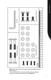
If you have damaged components, please contact Schwinn at 1.800.864.1270 2 I-10 Carriage Bolt M8xP1.25x85MM (1) I-1 M8xP1.25x85mm I-4 lock nut for M8 � (1) I-2 Knob (1) I-7 Allen Bolt M8xP1.0x45mm (4) Screwdriver I-6 Screws M8x16mm Socket Wrench���� ���� HARDWARE Note: Please verify you are missing items, are short quantities, or have all correct parts and quantities before assembling unit.
If you have damaged components, please contact Schwinn at 1.800.864.1270 2 I-10 Carriage Bolt M8xP1.25x85MM (1) I-1 M8xP1.25x85mm I-4 lock nut for M8 � (1) I-2 Knob (1) I-7 Allen Bolt M8xP1.0x45mm (4) Screwdriver I-6 Screws M8x16mm Socket Wrench���� ���� HARDWARE Note: Please verify you are missing items, are short quantities, or have all correct parts and quantities before assembling unit.
Assembly Manual
Page 5
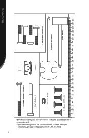
Note: Please verify you are missing items, are short quantities, or have all correct parts and quantities before assembling unit. If you have damaged components, please contact Schwinn at 1.800.864.1270 3 I-7 Allen Bolt M8xP1.0x45mm (4) Allen Key���� 4) I-3 Regular Washer 8*16*2t(15) I-5 Allen Bolt M8xP1.25x16mm (5) ���� HARDWARE
Note: Please verify you are missing items, are short quantities, or have all correct parts and quantities before assembling unit. If you have damaged components, please contact Schwinn at 1.800.864.1270 3 I-7 Allen Bolt M8xP1.0x45mm (4) Allen Key���� 4) I-3 Regular Washer 8*16*2t(15) I-5 Allen Bolt M8xP1.25x16mm (5) ���� HARDWARE
Assembly Manual
Page 7
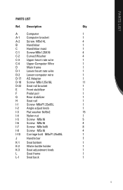
PARTS LIST PARTS LIST Ref. Description Qty A Computer 1 A-1 Computer bracket 1 A-2 Screw M5x14L 4 B Handlebar 1 C Handlebar mast 1 C-1 Screw M8x1.25X16 4 C-2 Curved Washer 4 C-3 Upper heart rate wire 1 C-4 Upper Computer Wire 1 D Main ...
PARTS LIST PARTS LIST Ref. Description Qty A Computer 1 A-1 Computer bracket 1 A-2 Screw M5x14L 4 B Handlebar 1 C Handlebar mast 1 C-1 Screw M8x1.25X16 4 C-2 Curved Washer 4 C-3 Upper heart rate wire 1 C-4 Upper Computer Wire 1 D Main ...
Assembly Manual
Page 9
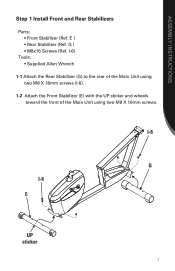
G ) • M8x16 Screws (Ref. I-6) Tools: • Supplied Allen Wrench 1-1 Attach the Rear Stabilizer (G) to the rear of the Main Unit using two M8 X 16mm screws. ASSEMBLY INSTRUCTIONS Step 1 Install Front and Rear Stabilizers Parts: • Front Stabilizer (Ref. I-6 G I -6). 1-2 Attach the Front Stabilizer (E) with the UP sticker and wheels toward the front of the Main Unit using two M8 X 16mm screws (I -6 E UP sticker 7 E ) • Rear Stabilizer (Ref.
G ) • M8x16 Screws (Ref. I-6) Tools: • Supplied Allen Wrench 1-1 Attach the Rear Stabilizer (G) to the rear of the Main Unit using two M8 X 16mm screws. ASSEMBLY INSTRUCTIONS Step 1 Install Front and Rear Stabilizers Parts: • Front Stabilizer (Ref. I-6 G I -6). 1-2 Attach the Front Stabilizer (E) with the UP sticker and wheels toward the front of the Main Unit using two M8 X 16mm screws (I -6 E UP sticker 7 E ) • Rear Stabilizer (Ref.
Assembly Manual
Page 10
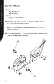
Note: The Left Pedal has a left handed thread and screws in counter clockwise. 2-2 Screw the Right Pedal ( has an "R "stamped into the end of the pedal ) into the Right Crank Arm. ASSEMBLY INSTRUCTIONS Step 2 Install Pedals Parts: • Right Pedal (F-R) • Right Pedal (F-L) Tools: • Supplied Pedal Wrench 2-1 Screw the Left Pedal ( has an "L" stamped into the end of the pedal ) into the Left Crank Arm. F-R F-L 8
Note: The Left Pedal has a left handed thread and screws in counter clockwise. 2-2 Screw the Right Pedal ( has an "R "stamped into the end of the pedal ) into the Right Crank Arm. ASSEMBLY INSTRUCTIONS Step 2 Install Pedals Parts: • Right Pedal (F-R) • Right Pedal (F-L) Tools: • Supplied Pedal Wrench 2-1 Screw the Left Pedal ( has an "L" stamped into the end of the pedal ) into the Left Crank Arm. F-R F-L 8
Assembly Manual
Page 11
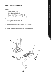
I -3 9 J) • Four M8x16 screws (Ref. ASSEMBLY INSTRUCTIONS Step 3 Install Handlebar Parts: • Seat Frame (Ref. L J I-5 I -5) • Four 8x16x2 Washers (Ref. I-3) Tools: • Supplied Allen Wrench 3-1 Align Handlebar with holes in Seat Frame. 3-2 Install and completely tighten the hardware. L) • Handlebar (Ref.
I -3 9 J) • Four M8x16 screws (Ref. ASSEMBLY INSTRUCTIONS Step 3 Install Handlebar Parts: • Seat Frame (Ref. L J I-5 I -5) • Four 8x16x2 Washers (Ref. I-3) Tools: • Supplied Allen Wrench 3-1 Align Handlebar with holes in Seat Frame. 3-2 Install and completely tighten the hardware. L) • Handlebar (Ref.
Assembly Manual
Page 12
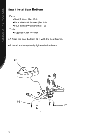
I -7 10 K-1 I-3 I -7) • Four 8x16x2 Washers (Ref. K-1) • Four M8x1x45 Screws (Ref. I-3) Tools: • Supplied Allen Wrench 4-1 Align the Seat Bottom (K-1) with the Seat Frame. 4-2 Install and completely tighten the hardware. ASSEMBLY INSTRUCTIONS Step 4 Install Seat Bottom Parts: • Seat Bottom (Ref.
I -7 10 K-1 I-3 I -7) • Four 8x16x2 Washers (Ref. K-1) • Four M8x1x45 Screws (Ref. I-3) Tools: • Supplied Allen Wrench 4-1 Align the Seat Bottom (K-1) with the Seat Frame. 4-2 Install and completely tighten the hardware. ASSEMBLY INSTRUCTIONS Step 4 Install Seat Bottom Parts: • Seat Bottom (Ref.
Assembly Manual
Page 13
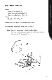
I -3) Tools: • Supplied Allen Wrench 5-1 Align the Seat Back (L-1) with the Seat Frame. 5-2 Install and completely tighten the hardware. You may use the upper or lower set of holes in the Seat Back. I -7) • Four 8x16x2 Washers (Ref. ASSEMBLY INSTRUCTIONS Step 5 Install Seat back Parts: • Seat Bottom (Ref. L-1 I-7 I-3 11 Note: There are two sets of holes to find the the most comfortable position. L-1) • Four M8x1x45 Screws (Ref.
I -3) Tools: • Supplied Allen Wrench 5-1 Align the Seat Back (L-1) with the Seat Frame. 5-2 Install and completely tighten the hardware. You may use the upper or lower set of holes in the Seat Back. I -7) • Four 8x16x2 Washers (Ref. ASSEMBLY INSTRUCTIONS Step 5 Install Seat back Parts: • Seat Bottom (Ref. L-1 I-7 I-3 11 Note: There are two sets of holes to find the the most comfortable position. L-1) • Four M8x1x45 Screws (Ref.
Assembly Manual
Page 14
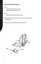
K-2) • Four M5x16 Screws (Ref. I -8 K-2 12 ASSEMBLY INSTRUCTIONS Step 6 Install Bottle Holder Parts: • Water Bottle Holder (Ref. I -8) Tools: • Supplied Phillips Head Screwdriver 6-1 Align the Water Bottle Holder under the left side of the Seat Bottom. 6-2 Install and completely tighten the hardware.
K-2) • Four M5x16 Screws (Ref. I -8 K-2 12 ASSEMBLY INSTRUCTIONS Step 6 Install Bottle Holder Parts: • Water Bottle Holder (Ref. I -8) Tools: • Supplied Phillips Head Screwdriver 6-1 Align the Water Bottle Holder under the left side of the Seat Bottom. 6-2 Install and completely tighten the hardware.
Assembly Manual
Page 16
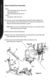
... Wrench 8-1 Pull out on the main unit. 8-4 Connect the Heart Rate Wire (M) to lock the Seat Assembly in place. ASSEMBLY INSTRUCTIONS Step 8 Install Seat Assembly Parts: • Seat Assembly (From step 3-6) • Seat Rail (Ref.
... Wrench 8-1 Pull out on the main unit. 8-4 Connect the Heart Rate Wire (M) to lock the Seat Assembly in place. ASSEMBLY INSTRUCTIONS Step 8 Install Seat Assembly Parts: • Seat Assembly (From step 3-6) • Seat Rail (Ref.
Assembly Manual
Page 17
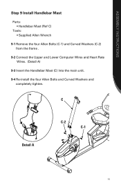
C Detail A C-2 C-1 15 ASSEMBLY INSTRUCTIONS Step 9 Install Handlebar Mast Parts: • Handlebar Mast (Ref C) Tools: • Supplied Allen Wrench 9-1 Remove the four Allen Bolts (C-1) and Curved Washers (C-2) from the frame . 9-2 Connect the Upper and Lower Computer Wires and Heart Rate Wires. (Detail A) 9-3 Insert the Handlebar Mast (C) into the main unit. 9-4 Re-install the four Allen Bolts and Curved Washers and completely tighten.
C Detail A C-2 C-1 15 ASSEMBLY INSTRUCTIONS Step 9 Install Handlebar Mast Parts: • Handlebar Mast (Ref C) Tools: • Supplied Allen Wrench 9-1 Remove the four Allen Bolts (C-1) and Curved Washers (C-2) from the frame . 9-2 Connect the Upper and Lower Computer Wires and Heart Rate Wires. (Detail A) 9-3 Insert the Handlebar Mast (C) into the main unit. 9-4 Re-install the four Allen Bolts and Curved Washers and completely tighten.
Assembly Manual
Page 18
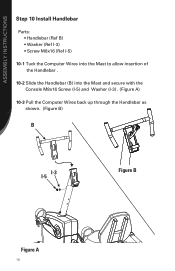
ASSEMBLY INSTRUCTIONS Step 10 Install Handlebar Parts: • Handlebar (Ref B) • Washer (Ref I-3) • Screw M8x16 (Ref I-5) 10-1 Tuck the Computer Wires into the Mast to allow insertion of the Handlebar . 10-2 Slide the Handlebar (B) into the Mast and secure with the Console M8x16 Screw (I-5) and Washer (I-3) . (Figure A) 10-3 Pull the Computer Wires back up through the Handlebar as shown. (Figure B) B I-3 I-5 Figure B Figure A 16
ASSEMBLY INSTRUCTIONS Step 10 Install Handlebar Parts: • Handlebar (Ref B) • Washer (Ref I-3) • Screw M8x16 (Ref I-5) 10-1 Tuck the Computer Wires into the Mast to allow insertion of the Handlebar . 10-2 Slide the Handlebar (B) into the Mast and secure with the Console M8x16 Screw (I-5) and Washer (I-3) . (Figure A) 10-3 Pull the Computer Wires back up through the Handlebar as shown. (Figure B) B I-3 I-5 Figure B Figure A 16
Assembly Manual
Page 19
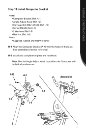
... (A-1) with the holes in the Mast. (See assembled view for reference) 11-2 Install and completely tighten the hardware. ASSEMBLY INSTRUCTIONS Step 11 Install Computer Bracket Parts: • Computer Bracket (Ref. I -2) • Carriage Bolt M8x1.25x85 (Ref.
... (A-1) with the holes in the Mast. (See assembled view for reference) 11-2 Install and completely tighten the hardware. ASSEMBLY INSTRUCTIONS Step 11 Install Computer Bracket Parts: • Computer Bracket (Ref. I -2) • Carriage Bolt M8x1.25x85 (Ref.


