Owner's Manual
Page 2
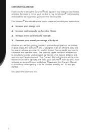
... q Decrease your exercise and fitness activities. Take your progress by tracking time, speed, distance and approximate Calories burned. This Schwinn® bike should enable you pursue your personal fitness goals. So let's get started in its entirety before getting started . Also included... or are general fitness guidelines. The on Schwinn® craftsmanship and durability as you to shape and monitor your workouts to accurately monitor your time and have fun! 2 CONGRATULATIONS! Thank you for making the Schwinn® bike a part of your overall percentage of fitness.
... q Decrease your exercise and fitness activities. Take your progress by tracking time, speed, distance and approximate Calories burned. This Schwinn® bike should enable you pursue your personal fitness goals. So let's get started in its entirety before getting started . Also included... or are general fitness guidelines. The on Schwinn® craftsmanship and durability as you to shape and monitor your workouts to accurately monitor your time and have fun! 2 CONGRATULATIONS! Thank you for making the Schwinn® bike a part of your overall percentage of fitness.
Owner's Manual
Page 4
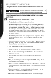
...word "Warning" found in this equipment, observe the following definition applies to children. 4. Contact Nautilus Customer Service. 6. This machine contains moving parts. This machine is a free area of wear. Operate the machine in the manner described in death or serious injury. Keep children away ...2. This exercise machine is not suitable as a children's toy. Set up and operate this manual. Make sure that there is designed for loose parts or signs of 19.7 inches ( 0.5 m) on all Warnings on exercise equipment, and parents and others in use. 12. Read and understand ...
...word "Warning" found in this equipment, observe the following definition applies to children. 4. Contact Nautilus Customer Service. 6. This machine contains moving parts. This machine is a free area of wear. Operate the machine in the manner described in death or serious injury. Keep children away ...2. This exercise machine is not suitable as a children's toy. Set up and operate this manual. Make sure that there is designed for loose parts or signs of 19.7 inches ( 0.5 m) on all Warnings on exercise equipment, and parents and others in use. 12. Read and understand ...
Owner's Manual
Page 24
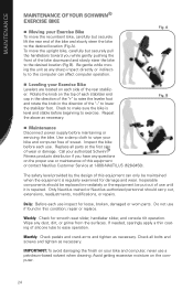
... the equipment is repaired. Check all parts at the first sign of silicone lube to raise the leveler foot and rotate the knob in this equipment or contact Nautilus Customer Service at 1-800-NAUTILUS (628-8458). To move the recumbent bike, carefully but securely pull the handlebars ... of the "-" to lower the stabilizer foot. MAINTENANCE MAINTENANCE OF YOUR SCHWINN® EXERCISE BIKE n Moving your Exercise Bike To move the upright bike, carefully but securely lift the rear end of the bike and slowly steer the bike to the desired location (Fig A). Be gentle while moving the unit as...
... the equipment is repaired. Check all parts at the first sign of silicone lube to raise the leveler foot and rotate the knob in this equipment or contact Nautilus Customer Service at 1-800-NAUTILUS (628-8458). To move the recumbent bike, carefully but securely pull the handlebars ... of the "-" to lower the stabilizer foot. MAINTENANCE MAINTENANCE OF YOUR SCHWINN® EXERCISE BIKE n Moving your Exercise Bike To move the upright bike, carefully but securely lift the rear end of the bike and slowly steer the bike to the desired location (Fig A). Be gentle while moving the unit as...
Owner's Manual
Page 26
... beliefs. Set aside an area or a room in your house or apartment that it is exclusively for several times per week at all. Make fitness a part of times a day, "I am living a healthier lifestyle by exercising several years or new to an exercise program, be sure to fit it in . Affirmations will...
... beliefs. Set aside an area or a room in your house or apartment that it is exclusively for several times per week at all. Make fitness a part of times a day, "I am living a healthier lifestyle by exercising several years or new to an exercise program, be sure to fit it in . Affirmations will...
Owner's Manual
Page 28
... and muscle mass as we perform daily tasks, play or exercise. Don't just do with comfort and ease as push-ups or lunges. The best part is not complicated. You can do all -in trying the Nautilus® yoga workout video. For women, strength training (along with cardiovascular training) may also...
... and muscle mass as we perform daily tasks, play or exercise. Don't just do with comfort and ease as push-ups or lunges. The best part is not complicated. You can do all -in trying the Nautilus® yoga workout video. For women, strength training (along with cardiovascular training) may also...
Owner's Manual
Page 37
...limitations and exclusions may not apply to follow instructions or warnings in the Owner's Manual. 4. is the responsibility of the parts supplier. 2. See your Authorized Schwinn® Fitness Dealer for assistance or questions. 37 THIS WARRANTY DOES NOT COVER 1. shall in no event be performed by...(628-8458) for service or write to repair or replace any cost, damage, failure or loss caused by the use a replacement part not supplied by Schwinn® Fitness warranty policies and procedures. In the event a product cannot be liable for which require warranty service. 2. If you ....
...limitations and exclusions may not apply to follow instructions or warnings in the Owner's Manual. 4. is the responsibility of the parts supplier. 2. See your Authorized Schwinn® Fitness Dealer for assistance or questions. 37 THIS WARRANTY DOES NOT COVER 1. shall in no event be performed by...(628-8458) for service or write to repair or replace any cost, damage, failure or loss caused by the use a replacement part not supplied by Schwinn® Fitness warranty policies and procedures. In the event a product cannot be liable for which require warranty service. 2. If you ....

Assembly Manual
Page 3
CONTENTS Table of Contents Hardware 2 Exploded View 4 Parts List 5 Assembly Instructions 6 Important Contact Numbers 21 1
CONTENTS Table of Contents Hardware 2 Exploded View 4 Parts List 5 Assembly Instructions 6 Important Contact Numbers 21 1
Assembly Manual
Page 4
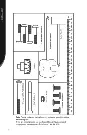
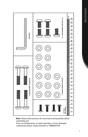
If you have damaged components, please contact Schwinn at 1.800.864.1270 2 I-10 Carriage Bolt M8xP1.25x85MM (1) I-1 M8xP1.25x85mm I-4 lock nut for M8 � (1) I-2 Knob (1) I-7 Allen Bolt M8xP1.0x45mm (4) Screwdriver I-6 Screws M8x16mm Socket Wrench���� ���� HARDWARE Note: Please verify you are missing items, are short quantities, or have all correct parts and quantities before assembling unit.
If you have damaged components, please contact Schwinn at 1.800.864.1270 2 I-10 Carriage Bolt M8xP1.25x85MM (1) I-1 M8xP1.25x85mm I-4 lock nut for M8 � (1) I-2 Knob (1) I-7 Allen Bolt M8xP1.0x45mm (4) Screwdriver I-6 Screws M8x16mm Socket Wrench���� ���� HARDWARE Note: Please verify you are missing items, are short quantities, or have all correct parts and quantities before assembling unit.
Assembly Manual
Page 5
Note: Please verify you are missing items, are short quantities, or have all correct parts and quantities before assembling unit. If you have damaged components, please contact Schwinn at 1.800.864.1270 3 I-7 Allen Bolt M8xP1.0x45mm (4) Allen Key���� 4) I-3 Regular Washer 8*16*2t(15) I-5 Allen Bolt M8xP1.25x16mm (5) ���� HARDWARE
Note: Please verify you are missing items, are short quantities, or have all correct parts and quantities before assembling unit. If you have damaged components, please contact Schwinn at 1.800.864.1270 3 I-7 Allen Bolt M8xP1.0x45mm (4) Allen Key���� 4) I-3 Regular Washer 8*16*2t(15) I-5 Allen Bolt M8xP1.25x16mm (5) ���� HARDWARE
Assembly Manual
Page 7
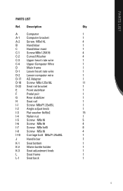
PARTS LIST PARTS LIST Ref. Description Qty A Computer 1 A-1 Computer bracket 1 A-2 Screw M5x14L 4 B Handlebar 1 C Handlebar mast 1 C-1 Screw M8x1.25X16 4 C-2 Curved Washer 4 C-3 Upper heart rate wire 1 C-4 Upper Computer Wire 1 D Main ...
PARTS LIST PARTS LIST Ref. Description Qty A Computer 1 A-1 Computer bracket 1 A-2 Screw M5x14L 4 B Handlebar 1 C Handlebar mast 1 C-1 Screw M8x1.25X16 4 C-2 Curved Washer 4 C-3 Upper heart rate wire 1 C-4 Upper Computer Wire 1 D Main ...
Assembly Manual
Page 9
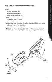
I-6 G I -6). 1-2 Attach the Front Stabilizer (E) with the UP sticker and wheels toward the front of the Main Unit using two M8 X 16mm screws. I-6) Tools: • Supplied Allen Wrench 1-1 Attach the Rear Stabilizer (G) to the rear of the Main Unit using two M8 X 16mm screws (I -6 E UP sticker 7 E ) • Rear Stabilizer (Ref. ASSEMBLY INSTRUCTIONS Step 1 Install Front and Rear Stabilizers Parts: • Front Stabilizer (Ref. G ) • M8x16 Screws (Ref.
I-6 G I -6). 1-2 Attach the Front Stabilizer (E) with the UP sticker and wheels toward the front of the Main Unit using two M8 X 16mm screws. I-6) Tools: • Supplied Allen Wrench 1-1 Attach the Rear Stabilizer (G) to the rear of the Main Unit using two M8 X 16mm screws (I -6 E UP sticker 7 E ) • Rear Stabilizer (Ref. ASSEMBLY INSTRUCTIONS Step 1 Install Front and Rear Stabilizers Parts: • Front Stabilizer (Ref. G ) • M8x16 Screws (Ref.
Assembly Manual
Page 10
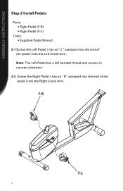
Note: The Left Pedal has a left handed thread and screws in counter clockwise. 2-2 Screw the Right Pedal ( has an "R "stamped into the end of the pedal ) into the Right Crank Arm. F-R F-L 8 ASSEMBLY INSTRUCTIONS Step 2 Install Pedals Parts: • Right Pedal (F-R) • Right Pedal (F-L) Tools: • Supplied Pedal Wrench 2-1 Screw the Left Pedal ( has an "L" stamped into the end of the pedal ) into the Left Crank Arm.
Note: The Left Pedal has a left handed thread and screws in counter clockwise. 2-2 Screw the Right Pedal ( has an "R "stamped into the end of the pedal ) into the Right Crank Arm. F-R F-L 8 ASSEMBLY INSTRUCTIONS Step 2 Install Pedals Parts: • Right Pedal (F-R) • Right Pedal (F-L) Tools: • Supplied Pedal Wrench 2-1 Screw the Left Pedal ( has an "L" stamped into the end of the pedal ) into the Left Crank Arm.
Assembly Manual
Page 11
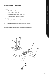
L) • Handlebar (Ref. J) • Four M8x16 screws (Ref. I -3 9 L J I-5 I -5) • Four 8x16x2 Washers (Ref. ASSEMBLY INSTRUCTIONS Step 3 Install Handlebar Parts: • Seat Frame (Ref. I-3) Tools: • Supplied Allen Wrench 3-1 Align Handlebar with holes in Seat Frame. 3-2 Install and completely tighten the hardware.
L) • Handlebar (Ref. J) • Four M8x16 screws (Ref. I -3 9 L J I-5 I -5) • Four 8x16x2 Washers (Ref. ASSEMBLY INSTRUCTIONS Step 3 Install Handlebar Parts: • Seat Frame (Ref. I-3) Tools: • Supplied Allen Wrench 3-1 Align Handlebar with holes in Seat Frame. 3-2 Install and completely tighten the hardware.
Assembly Manual
Page 12
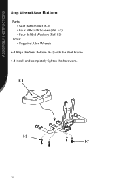
I -7 10 K-1) • Four M8x1x45 Screws (Ref. K-1 I-3 I -3) Tools: • Supplied Allen Wrench 4-1 Align the Seat Bottom (K-1) with the Seat Frame. 4-2 Install and completely tighten the hardware. I-7) • Four 8x16x2 Washers (Ref. ASSEMBLY INSTRUCTIONS Step 4 Install Seat Bottom Parts: • Seat Bottom (Ref.
I -7 10 K-1) • Four M8x1x45 Screws (Ref. K-1 I-3 I -3) Tools: • Supplied Allen Wrench 4-1 Align the Seat Bottom (K-1) with the Seat Frame. 4-2 Install and completely tighten the hardware. I-7) • Four 8x16x2 Washers (Ref. ASSEMBLY INSTRUCTIONS Step 4 Install Seat Bottom Parts: • Seat Bottom (Ref.
Assembly Manual
Page 13
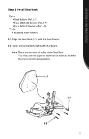
L-1) • Four M8x1x45 Screws (Ref. ASSEMBLY INSTRUCTIONS Step 5 Install Seat back Parts: • Seat Bottom (Ref. I -3 11 You may use the upper or lower set of holes in the Seat Back. Note: There are two sets of holes to find the the most comfortable position. L-1 I-7 I -3) Tools: • Supplied Allen Wrench 5-1 Align the Seat Back (L-1) with the Seat Frame. 5-2 Install and completely tighten the hardware. I-7) • Four 8x16x2 Washers (Ref.
L-1) • Four M8x1x45 Screws (Ref. ASSEMBLY INSTRUCTIONS Step 5 Install Seat back Parts: • Seat Bottom (Ref. I -3 11 You may use the upper or lower set of holes in the Seat Back. Note: There are two sets of holes to find the the most comfortable position. L-1 I-7 I -3) Tools: • Supplied Allen Wrench 5-1 Align the Seat Back (L-1) with the Seat Frame. 5-2 Install and completely tighten the hardware. I-7) • Four 8x16x2 Washers (Ref.
Assembly Manual
Page 14
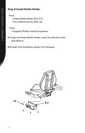
K-2) • Four M5x16 Screws (Ref. I -8) Tools: • Supplied Phillips Head Screwdriver 6-1 Align the Water Bottle Holder under the left side of the Seat Bottom. 6-2 Install and completely tighten the hardware. I -8 K-2 12 ASSEMBLY INSTRUCTIONS Step 6 Install Bottle Holder Parts: • Water Bottle Holder (Ref.
K-2) • Four M5x16 Screws (Ref. I -8) Tools: • Supplied Phillips Head Screwdriver 6-1 Align the Water Bottle Holder under the left side of the Seat Bottom. 6-2 Install and completely tighten the hardware. I -8 K-2 12 ASSEMBLY INSTRUCTIONS Step 6 Install Bottle Holder Parts: • Water Bottle Holder (Ref.
Assembly Manual
Page 16
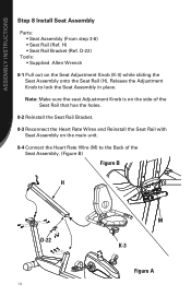
... Seat Rail with Seat Assembly on the Seat Adjustment Knob (K-3) while sliding the Seat Assembly onto the Seat Rail (H). ASSEMBLY INSTRUCTIONS Step 8 Install Seat Assembly Parts: • Seat Assembly (From step 3-6) • Seat Rail (Ref.
... Seat Rail with Seat Assembly on the Seat Adjustment Knob (K-3) while sliding the Seat Assembly onto the Seat Rail (H). ASSEMBLY INSTRUCTIONS Step 8 Install Seat Assembly Parts: • Seat Assembly (From step 3-6) • Seat Rail (Ref.
Assembly Manual
Page 17
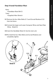
C Detail A C-2 C-1 15 ASSEMBLY INSTRUCTIONS Step 9 Install Handlebar Mast Parts: • Handlebar Mast (Ref C) Tools: • Supplied Allen Wrench 9-1 Remove the four Allen Bolts (C-1) and Curved Washers (C-2) from the frame . 9-2 Connect the Upper and Lower Computer Wires and Heart Rate Wires. (Detail A) 9-3 Insert the Handlebar Mast (C) into the main unit. 9-4 Re-install the four Allen Bolts and Curved Washers and completely tighten.
C Detail A C-2 C-1 15 ASSEMBLY INSTRUCTIONS Step 9 Install Handlebar Mast Parts: • Handlebar Mast (Ref C) Tools: • Supplied Allen Wrench 9-1 Remove the four Allen Bolts (C-1) and Curved Washers (C-2) from the frame . 9-2 Connect the Upper and Lower Computer Wires and Heart Rate Wires. (Detail A) 9-3 Insert the Handlebar Mast (C) into the main unit. 9-4 Re-install the four Allen Bolts and Curved Washers and completely tighten.
Assembly Manual
Page 18
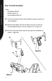
ASSEMBLY INSTRUCTIONS Step 10 Install Handlebar Parts: • Handlebar (Ref B) • Washer (Ref I-3) • Screw M8x16 (Ref I-5) 10-1 Tuck the Computer Wires into the Mast to allow insertion of the Handlebar . 10-2 Slide the Handlebar (B) into the Mast and secure with the Console M8x16 Screw (I-5) and Washer (I-3) . (Figure A) 10-3 Pull the Computer Wires back up through the Handlebar as shown. (Figure B) B I-3 I-5 Figure B Figure A 16
ASSEMBLY INSTRUCTIONS Step 10 Install Handlebar Parts: • Handlebar (Ref B) • Washer (Ref I-3) • Screw M8x16 (Ref I-5) 10-1 Tuck the Computer Wires into the Mast to allow insertion of the Handlebar . 10-2 Slide the Handlebar (B) into the Mast and secure with the Console M8x16 Screw (I-5) and Washer (I-3) . (Figure A) 10-3 Pull the Computer Wires back up through the Handlebar as shown. (Figure B) B I-3 I-5 Figure B Figure A 16
Assembly Manual
Page 19
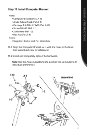
I -2) • Carriage Bolt M8x1.25x85 (Ref. ASSEMBLY INSTRUCTIONS Step 11 Install Computer Bracket Parts: • Computer Bracket (Ref. Note: Use the Angle Adjust Knob to position the Computer to fit individual preferences. I -4) Tools: • Supplied Socket and Flat Wrenches ...
I -2) • Carriage Bolt M8x1.25x85 (Ref. ASSEMBLY INSTRUCTIONS Step 11 Install Computer Bracket Parts: • Computer Bracket (Ref. Note: Use the Angle Adjust Knob to position the Computer to fit individual preferences. I -4) Tools: • Supplied Socket and Flat Wrenches ...


