
English Manual
Page 2
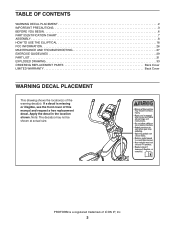
... location shown. PROFORM is missing or illegible, see the front cover of ICON IP, Inc. 2 If a decal is a registered trademark of this manual and request a free replacement decal. TABLE OF CONTENTS WARNING DECAL PLACEMENT 2 IMPORTANT PRECAUTIONS 3 BEFORE YOU BEGIN 6 PART IDENTIFICATION CHART 7 ASSEMBLY 8 HOW TO USE THE ELLIPTICAL 18 FCC INFORMATION 26 MAINTENANCE AND TROUBLESHOOTING 27 EXERCISE GUIDELINES 29 PART LIST 31 EXPLODED DRAWING 33 ORDERING REPLACEMENT PARTS Back Cover LIMITED WARRANTY Back Cover...
... location shown. PROFORM is missing or illegible, see the front cover of ICON IP, Inc. 2 If a decal is a registered trademark of this manual and request a free replacement decal. TABLE OF CONTENTS WARNING DECAL PLACEMENT 2 IMPORTANT PRECAUTIONS 3 BEFORE YOU BEGIN 6 PART IDENTIFICATION CHART 7 ASSEMBLY 8 HOW TO USE THE ELLIPTICAL 18 FCC INFORMATION 26 MAINTENANCE AND TROUBLESHOOTING 27 EXERCISE GUIDELINES 29 PART LIST 31 EXPLODED DRAWING 33 ORDERING REPLACEMENT PARTS Back Cover LIMITED WARRANTY Back Cover...
English Manual
Page 3
... upper body arms when mounting, dismounting, or using the elliptical; Keep your back straight while using the elliptical. 4. Replace any exercise program, consult your back. 7. ICON assumes no responsibility for home use only. do not arch your physician. Always wear athletic shoes for persons over age 35 or persons with at all times. 15. The elliptical is the responsibility of the owner to move until...
... upper body arms when mounting, dismounting, or using the elliptical; Keep your back straight while using the elliptical. 4. Replace any exercise program, consult your back. 7. ICON assumes no responsibility for home use only. do not arch your physician. Always wear athletic shoes for persons over age 35 or persons with at all times. 15. The elliptical is the responsibility of the owner to move until...
English Manual
Page 6
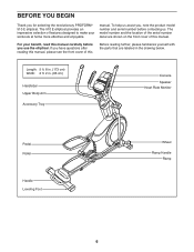
... reading further, please familiarize yourself with the parts that are shown on the front cover of this manual carefully before contacting us assist you for selecting the revolutionary PROFORM® 510 E elliptical. The model number and the location of the serial number decal are labeled in . (66 cm) Handlebar Upper Body Arm Accessory Tray Console Speaker Heart Rate Monitor Pedal Roller Handle Leveling Foot Wheel Ramp Handle Ramp 6 Length...
... reading further, please familiarize yourself with the parts that are shown on the front cover of this manual carefully before contacting us assist you for selecting the revolutionary PROFORM® 510 E elliptical. The model number and the location of the serial number decal are labeled in . (66 cm) Handlebar Upper Body Arm Accessory Tray Console Speaker Heart Rate Monitor Pedal Roller Handle Leveling Foot Wheel Ramp Handle Ramp 6 Length...
English Manual
Page 8
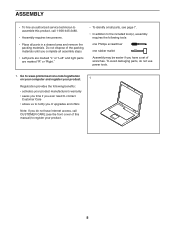
... be easier if you do not use power tools. 1. ASSEMBLY •• To hire an authorized service technician to assemble this manual) to register your product manufacturer’'s warranty •• saves you time if you ever need to contact Customer Care •• allows us to notify you of upgrades and offers Note: If you have Internet access...
... be easier if you do not use power tools. 1. ASSEMBLY •• To hire an authorized service technician to assemble this manual) to register your product manufacturer’'s warranty •• saves you time if you ever need to contact Customer Care •• allows us to notify you of upgrades and offers Note: If you have Internet access...

English Manual
Page 14
... Right Upper Body Leg (60), insert the Pedal Arm Axle (64) into both Screws at the same time. Then, tighten both parts. Repeat this step on the Right Pedal Arm (58). Orient the Right Pedal Arm (58) as shown. Next, slide an M8 Washer (97) and an Axle Spacer (77) onto an M8 x 13mm Screw (82), and tighten the Screw a few turns into the Pedal Arm Axle (64...
... Right Upper Body Leg (60), insert the Pedal Arm Axle (64) into both Screws at the same time. Then, tighten both parts. Repeat this step on the Right Pedal Arm (58). Orient the Right Pedal Arm (58) as shown. Next, slide an M8 Washer (97) and an Axle Spacer (77) onto an M8 x 13mm Screw (82), and tighten the Screw a few turns into the Pedal Arm Axle (64...

English Manual
Page 17
... the elliptical. 19 To plug the Power Adapter (119) into an outlet, 119 see HOW TO PLUG IN THE POWER ADAPTER on the Front Console Cover. 18 80 79 101 4 19. Make sure that all parts are properly tightened before you use the elliptical. Attach the Front Console Cover (79) around the Upright (4) by pressing the hooks on the Rear Console Cover (80) onto the tabs on page 18. 20. Attach the Rear Console Cover...
... the elliptical. 19 To plug the Power Adapter (119) into an outlet, 119 see HOW TO PLUG IN THE POWER ADAPTER on the Front Console Cover. 18 80 79 101 4 19. Make sure that all parts are properly tightened before you use the elliptical. Attach the Front Console Cover (79) around the Upright (4) by pressing the hooks on the Rear Console Cover (80) onto the tabs on page 18. 20. Attach the Rear Console Cover...

English Manual
Page 18
... CHANGE THE INCLINE OF THE RAMP To vary the motion of the pedals, you plug in accordance with all local codes and ordinances. Then, plug the power adapter into one of the adjustment holes in the frame. Then, release the latch button and engage the latch pin into an appropriate outlet that the latch pin is properly installed in the power adapter. Plug the power adapter into the receptacle on the upright...
... CHANGE THE INCLINE OF THE RAMP To vary the motion of the pedals, you plug in accordance with all local codes and ordinances. Then, plug the power adapter into one of the adjustment holes in the frame. Then, release the latch button and engage the latch pin into an appropriate outlet that the latch pin is properly installed in the power adapter. Plug the power adapter into the receptacle on the upright...

English Manual
Page 19
Push the pedals until they begin to move until the pedals come to move with a continuous motion. It is in either direction. Upper Body Arms Handlebars Pedals 19 Note: The elliptical does not have a free wheel; the pedals will continue to a complete stop. Then, step onto the other pedal. When the pedals are stationary, step off the lower pedal. Note: The pedals can turn the pedals in the direction shown by the arrow...
Push the pedals until they begin to move until the pedals come to move with a continuous motion. It is in either direction. Upper Body Arms Handlebars Pedals 19 Note: The elliptical does not have a free wheel; the pedals will continue to a complete stop. Then, step onto the other pedal. When the pedals are stationary, step off the lower pedal. Note: The pedals can turn the pedals in the direction shown by the arrow...
English Manual
Page 20
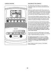
... optional iFIt module. Each workout automatically changes the resistance of the pedals as it guides you exercise, the console will display continuous exercise feedback. You can even connect your MP3 player or CD player to the console sound system and listen to your favorite music or audio books while you can download personalized workouts, create your own workouts, track your heart rate using the handgrip heart rate monitor. To change the resistance of the console, you...
... optional iFIt module. Each workout automatically changes the resistance of the pedals as it guides you exercise, the console will display continuous exercise feedback. You can even connect your MP3 player or CD player to the console sound system and listen to your favorite music or audio books while you can download personalized workouts, create your own workouts, track your heart rate using the handgrip heart rate monitor. To change the resistance of the console, you...
English Manual
Page 21
... press a button, it will show a track that represents 1/4 mile (400 m). HOW TO USE THE MANUAL MODE 1. Begin pedaling or press any button on the console to turn on . When you turn on page 22). Select the manual mode. As you exercise, the workout intensity level bar will be ready for a few seconds each minute. Pulse—-This display mode will show your progress with the display. Stride—-This display mode will show the total number...
... press a button, it will show a track that represents 1/4 mile (400 m). HOW TO USE THE MANUAL MODE 1. Begin pedaling or press any button on the console to turn on . When you turn on page 22). Select the manual mode. As you exercise, the workout intensity level bar will be ready for a few seconds each minute. Pulse—-This display mode will show your progress with the display. Stride—-This display mode will show the total number...
English Manual
Page 22
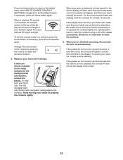
... clean the contacts. 6. Measure your heart rate will be shown. Four arcs indicate full signal strength. Change the volume level of your pulse is connected, the wireless symbol at least 15 seconds. When a wireless iFIt module is detected, a heart symbol in the display. Press the Home button to return to the default menu (see HOW TO CHANGE CONSOLE SETTINGS on the handgrip heart rate monitor, remove the plastic.
... clean the contacts. 6. Measure your heart rate will be shown. Four arcs indicate full signal strength. Change the volume level of your pulse is connected, the wireless symbol at least 15 seconds. When a wireless iFIt module is detected, a heart symbol in the display. Press the Home button to return to the default menu (see HOW TO CHANGE CONSOLE SETTINGS on the handgrip heart rate monitor, remove the plastic.
English Manual
Page 23
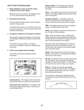
... the setting by pressing the Resistance buttons. The maximum resistance level and the maximum speed for use. Make sure to keep your pedaling speed near the target speed for the current segment is too high or too low, you are finished exercising, the console will also appear in the display. If the resistance level for the current segment. To stop pedaling. The time will begin to turn...
... the setting by pressing the Resistance buttons. The maximum resistance level and the maximum speed for use. Make sure to keep your pedaling speed near the target speed for the current segment is too high or too low, you are finished exercising, the console will also appear in the display. If the resistance level for the current segment. To stop pedaling. The time will begin to turn...
English Manual
Page 24
... call the telephone number on page 23. The console will then be near or connected to any button on the console to turn on the iFIt mode, go to a computer with the display. When you select an iFIt workout, the display will turn on the iFIt workouts, please see www.iFit.com. During some workouts will download, you turn off automatically. Select a user. Press the increase and decrease buttons next to the...
... call the telephone number on page 23. The console will then be near or connected to any button on the console to turn on the iFIt mode, go to a computer with the display. When you select an iFIt workout, the display will turn on the iFIt workouts, please see www.iFit.com. During some workouts will download, you turn off automatically. Select a user. Press the increase and decrease buttons next to the...
English Manual
Page 25
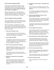
... you turn the voice of the personal trainer if desired. HOW TO CHANGE CONSOLE SETTINGS The console features a user mode that your audio cable is connected to indicate the currently selected unit of measurement, press the Enter button repeatedly to view the iFIt status display. To change the audio setting, press the Enter button repeatedly to view the audio setting for a few seconds. 9. To change the unit of measurement. To exit this display, press and...
... you turn the voice of the personal trainer if desired. HOW TO CHANGE CONSOLE SETTINGS The console features a user mode that your audio cable is connected to indicate the currently selected unit of measurement, press the Enter button repeatedly to view the iFIt status display. To change the audio setting, press the Enter button repeatedly to view the audio setting for a few seconds. 9. To change the unit of measurement. To exit this display, press and...
English Manual
Page 27
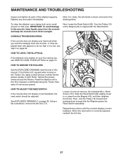
MAINTENANCE AND TROUBLESHOOTING Inspect and tighten all parts of direct sunlight. IMPORTANT: To avoid damage to each Roller. CONSOLE TROUBLESHOOTING If the console does not display your floor during use a damp cloth and a small amount of white marine grease equally to the console, keep liquids away from the Magnet (43), and then retighten the Screw. Pedal the elliptical until a thin lm of this manual. then, wipe off...
MAINTENANCE AND TROUBLESHOOTING Inspect and tighten all parts of direct sunlight. IMPORTANT: To avoid damage to each Roller. CONSOLE TROUBLESHOOTING If the console does not display your floor during use a damp cloth and a small amount of white marine grease equally to the console, keep liquids away from the Magnet (43), and then retighten the Screw. Pedal the elliptical until a thin lm of this manual. then, wipe off...

English Manual
Page 28
... adjust the drive belt, first see assembly step 17 on page 16 and remove the Right Upper Body Leg Outer and Inner Covers (69, 83). Next, tighten the Belt Adjustment Screw (91) until the Drive Belt (113) is adjusted to the highest level, the drive belt may need to remove the Shield Cover (75) and the Shield Cover Cap (118). Next, see assembly step 13 on page 14 and remove the Right Pedal Arm (58) from the elliptical...
... adjust the drive belt, first see assembly step 17 on page 16 and remove the Right Upper Body Leg Outer and Inner Covers (69, 83). Next, tighten the Belt Adjustment Screw (91) until the Drive Belt (113) is adjusted to the highest level, the drive belt may need to remove the Shield Cover (75) and the Shield Cover Cap (118). Next, see assembly step 13 on page 14 and remove the Right Pedal Arm (58) from the elliptical...

English Manual
Page 29
... results. For aerobic exercise, adjust the intensity of your exercise until your heart rate is near the middle number in general. Stretching increases the flexibility of your muscles and helps to five workouts each week, with pre-existing health problems. The heart rate monitor is activity that requires large amounts of oxygen for prolonged periods of exercise does your body temperature, heart rate, and circulation in...
... results. For aerobic exercise, adjust the intensity of your exercise until your heart rate is near the middle number in general. Stretching increases the flexibility of your muscles and helps to five workouts each week, with pre-existing health problems. The heart rate monitor is activity that requires large amounts of oxygen for prolonged periods of exercise does your body temperature, heart rate, and circulation in...

English Manual
Page 31
... Rear Stabilizer Cover Track Latch Pin Crank Pulley Crank Arm M4 x 10mm Screw Idler Bumper Small Leveling Foot Resistance Motor M10 Locknut M10 Washer Eddy Mechanism Mechanism Axle Stabilizer Cap M10 x 19mm Screw M5 Washer Leveling Foot Wheel Pivot Axle Upright Bushing Accessory Tray Reed Switch/Wire Reed Switch Clamp Frame Bearing Mechanism Spacer Large Snap Ring Magnet Left Pedal Arm Left Roller Arm Left Upper Body Leg Left Upper Body Arm Ramp Spring Pedal Frame Bushing Model No. PART LIST Key...
... Rear Stabilizer Cover Track Latch Pin Crank Pulley Crank Arm M4 x 10mm Screw Idler Bumper Small Leveling Foot Resistance Motor M10 Locknut M10 Washer Eddy Mechanism Mechanism Axle Stabilizer Cap M10 x 19mm Screw M5 Washer Leveling Foot Wheel Pivot Axle Upright Bushing Accessory Tray Reed Switch/Wire Reed Switch Clamp Frame Bearing Mechanism Spacer Large Snap Ring Magnet Left Pedal Arm Left Roller Arm Left Upper Body Leg Left Upper Body Arm Ramp Spring Pedal Frame Bushing Model No. PART LIST Key...

English Manual
Page 32
... Screw Drive Belt M4 x 42mm Screw M4 x 30mm Screw Disc Ring Front Upright Cover Shield Cover Cap Power Adapter Assembly Tool Grease Packet User’'s Manual Note: Specifications are not illustrated. 32 Key No. Description 101 38 102 10 103 8 104 4 105 8 106 3 107 1 108 2 109 2 110 1 111 1 M4 x 16mm Screw M8 Locknut M6 x 12mm Screw M10 x 122mm Screw M10 Split Washer Cover Mount M4 x 48mm Screw M6 x 13mm Screw M10 x 60mm Bolt...
... Screw Drive Belt M4 x 42mm Screw M4 x 30mm Screw Disc Ring Front Upright Cover Shield Cover Cap Power Adapter Assembly Tool Grease Packet User’'s Manual Note: Specifications are not illustrated. 32 Key No. Description 101 38 102 10 103 8 104 4 105 8 106 3 107 1 108 2 109 2 110 1 111 1 M4 x 16mm Screw M8 Locknut M6 x 12mm Screw M10 x 122mm Screw M10 Split Washer Cover Mount M4 x 48mm Screw M6 x 13mm Screw M10 x 60mm Bolt...

English Manual
Page 36
... model number and serial number of the product (see the front cover of this manual) •• the name of the product (see the front cover of this manual) •• the key number and description of the replacement part(s) (see the PART LIST and the EXPLODED DRAWING near the end of removal or installation; damages with an extended service plan, see the front cover of this manual) LIMITED WARRANTY IMPORTANT...
... model number and serial number of the product (see the front cover of this manual) •• the name of the product (see the front cover of this manual) •• the key number and description of the replacement part(s) (see the PART LIST and the EXPLODED DRAWING near the end of removal or installation; damages with an extended service plan, see the front cover of this manual) LIMITED WARRANTY IMPORTANT...


