
English Manual
Page 2
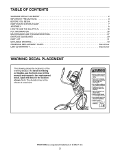
TABLE OF CONTENTS WARNING DECAL PLACEMENT 2 IMPORTANT PRECAUTIONS 3 BEFORE YOU BEGIN 6 PART IDENTIFICATION CHART 7 ASSEMBLY 8 HOW TO USE THE ELLIPTICAL 18 FCC INFORMATION 26 MAINTENANCE AND TROUBLESHOOTING 27 EXERCISE GUIDELINES 29 PART LIST 31 EXPLODED DRAWING 33 ORDERING REPLACEMENT PARTS Back Cover LIMITED WARRANTY Back ... a decal is a registered trademark of ICON IP, Inc. 2 Apply the decal in the location shown. Note: The decal(s) may not be shown at actual size. PROFORM is missing or illegible, see the front cover of the warning decal(s).
TABLE OF CONTENTS WARNING DECAL PLACEMENT 2 IMPORTANT PRECAUTIONS 3 BEFORE YOU BEGIN 6 PART IDENTIFICATION CHART 7 ASSEMBLY 8 HOW TO USE THE ELLIPTICAL 18 FCC INFORMATION 26 MAINTENANCE AND TROUBLESHOOTING 27 EXERCISE GUIDELINES 29 PART LIST 31 EXPLODED DRAWING 33 ORDERING REPLACEMENT PARTS Back Cover LIMITED WARRANTY Back ... a decal is a registered trademark of ICON IP, Inc. 2 Apply the decal in the location shown. Note: The decal(s) may not be shown at actual size. PROFORM is missing or illegible, see the front cover of the warning decal(s).
English Manual
Page 7
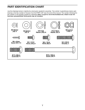
... x 38mm Bolt (96)–-4 M10 x 25mm Screw (92)–-4 M10 x 122mm Screw (104)–-4 7 The number following the key number is the quantity needed for assembly. PART IDENTIFICATION CHART Use the drawings below each drawing is the key number of the part, from the PART LIST near the end of this...
... x 38mm Bolt (96)–-4 M10 x 25mm Screw (92)–-4 M10 x 122mm Screw (104)–-4 7 The number following the key number is the quantity needed for assembly. PART IDENTIFICATION CHART Use the drawings below each drawing is the key number of the part, from the PART LIST near the end of this...
English Manual
Page 8
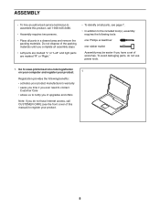
...www.proformservice.com/registration on your computer and register your product. 1 Registration provides the following tools: one Phillips screwdriver one rubber mallet Assembly may be easier if you complete all parts in a cleared area and remove the packing materials. To avoid damaging parts, do not.... 8 Do not dispose of the packing materials until you have Internet access, call 1-800-445-2480. •• Assembly requires two persons. •• Place all assembly steps. •• Left parts are marked “"L”" or “"Left”" and right parts are marked &#...
...www.proformservice.com/registration on your computer and register your product. 1 Registration provides the following tools: one Phillips screwdriver one rubber mallet Assembly may be easier if you complete all parts in a cleared area and remove the packing materials. To avoid damaging parts, do not.... 8 Do not dispose of the packing materials until you have Internet access, call 1-800-445-2480. •• Assembly requires two persons. •• Place all assembly steps. •• Left parts are marked “"L”" or “"Left”" and right parts are marked &#...

English Manual
Page 28
... page 35. Remove the Right Roller Arm (59) from the Left and Right Shields (73, 74). Next, see assembly step 17 on page 14 and remove the Right Pedal Arm (58) from the elliptical. 89 91 Reattach the right shield, the right roller arm, the right pedal arm, the shield cover cap... the right Crank Arm (20). Use a flat screwdriver to be adjusted. See EXPLODED DRAWING C on page 33. Then, see assembly step 13 on page 16. Then, carefully remove the Right Roller Arm assembly from the Right Upper Body 113 Leg (60). HOW TO ADJUST THE DRIVE BELT If the pedals slip while...
... page 35. Remove the Right Roller Arm (59) from the Left and Right Shields (73, 74). Next, see assembly step 17 on page 14 and remove the Right Pedal Arm (58) from the elliptical. 89 91 Reattach the right shield, the right roller arm, the right pedal arm, the shield cover cap... the right Crank Arm (20). Use a flat screwdriver to be adjusted. See EXPLODED DRAWING C on page 33. Then, see assembly step 13 on page 16. Then, carefully remove the Right Roller Arm assembly from the Right Upper Body 113 Leg (60). HOW TO ADJUST THE DRIVE BELT If the pedals slip while...

English Manual
Page 32
.... Key No. M4 x 19mm Self-tapping Screw Drive Belt M4 x 42mm Screw M4 x 30mm Screw Disc Ring Front Upright Cover Shield Cover Cap Power Adapter Assembly Tool Grease Packet User’'s Manual Note: Specifications are not illustrated. 32
.... Key No. M4 x 19mm Self-tapping Screw Drive Belt M4 x 42mm Screw M4 x 30mm Screw Disc Ring Front Upright Cover Shield Cover Cap Power Adapter Assembly Tool Grease Packet User’'s Manual Note: Specifications are not illustrated. 32


