
Owner's Manual
Page 1
...CHANNEL RECEIVER VSX-918V VSX-818V Register your product at www.pioneerelectronics.com (US) www.pioneerelectronics.ca (Canada) • Protect your new investment The details of your purchase will be on file for reference in the event of an insurance claim such as loss or theft. • Receive free ...tips, updates and service bulletins on your new product • Improve product development Your input helps us continue to design products that meet your needs. • Receive a free Pioneer newsletter Registered customers can opt in to...
...CHANNEL RECEIVER VSX-918V VSX-818V Register your product at www.pioneerelectronics.com (US) www.pioneerelectronics.ca (Canada) • Protect your new investment The details of your purchase will be on file for reference in the event of an insurance claim such as loss or theft. • Receive free ...tips, updates and service bulletins on your new product • Improve product development Your input helps us continue to design products that meet your needs. • Receive a free Pioneer newsletter Registered customers can opt in to...

Owner's Manual
Page 2
... appareil numérique de la Classe B est conforme à la norme NMB-003 du Canada. Product Name: AUDIO/VIDEO MULTI-CHANNEL RECEIVER Model Number: VSX-918V-K, VSX-918V-S, VSX-818V-K, VSX-818V-S Responsible Party Name: PIONEER ELECTRONICS SERVICE INC. WARNING This equipment is connected. - D3-4-2-1-3_B_En WARNING Before plugging in a particular installation. If connected to cause cancer...
... appareil numérique de la Classe B est conforme à la norme NMB-003 du Canada. Product Name: AUDIO/VIDEO MULTI-CHANNEL RECEIVER Model Number: VSX-918V-K, VSX-918V-S, VSX-818V-K, VSX-818V-S Responsible Party Name: PIONEER ELECTRONICS SERVICE INC. WARNING This equipment is connected. - D3-4-2-1-3_B_En WARNING Before plugging in a particular installation. If connected to cause cancer...
Owner's Manual
Page 4
... effects . . . . . 31 Listening in a safe place for buying this Pioneer product. Please read through these operating instructions so you start Checking what's in the box 6 Loading the batteries 6 Installing the receiver 6 Ventilation 6 04 Controls and displays Front panel 23 Display 24 Remote control 26 ... audio cables 11 Video cables 11 Connecting a DVD player and TV 12 Connecting the multichannel analog outputs 13 Connecting a satellite receiver or other digital set-top box 13 Connecting other audio components 14 About the WMA9 Pro decoder 14 Connecting an HDD/DVD recorder...
... effects . . . . . 31 Listening in a safe place for buying this Pioneer product. Please read through these operating instructions so you start Checking what's in the box 6 Loading the batteries 6 Installing the receiver 6 Ventilation 6 04 Controls and displays Front panel 23 Display 24 Remote control 26 ... audio cables 11 Video cables 11 Connecting a DVD player and TV 12 Connecting the multichannel analog outputs 13 Connecting a satellite receiver or other digital set-top box 13 Connecting other audio components 14 About the WMA9 Pro decoder 14 Connecting an HDD/DVD recorder...

Owner's Manual
Page 5
...-7-3_En English Italiano Français Deutsch Nederlands Español and "DTS 96/24" is a registered trademark of your system Operating other Pioneer components 49 Setting the remote to control other components 49 Selecting preset codes directly 50 Direct function 50 Clearing all the remote control settings. .... . . 60 Listening to SIRIUS Radio 61 Saving channel presets 61 Using the SIRIUS Menu 62 Using this receiver with a Pioneer plasma display 62 Using the SR+ mode with a Pioneer plasma display 63 11 Other Settings The Input Assign menu 64 The Other Setup menu 66 SR+ Setup for...
...-7-3_En English Italiano Français Deutsch Nederlands Español and "DTS 96/24" is a registered trademark of your system Operating other Pioneer components 49 Setting the remote to control other components 49 Selecting preset codes directly 50 Direct function 50 Clearing all the remote control settings. .... . . 60 Listening to SIRIUS Radio 61 Saving channel presets 61 Using the SIRIUS Menu 62 Using this receiver with a Pioneer plasma display 62 Using the SR+ mode with a Pioneer plasma display 63 11 Other Settings The Input Assign menu 64 The Other Setup menu 66 SR+ Setup for...

Owner's Manual
Page 6
... off a magnetic field). in places that you start Chapter 1: Before you 've received the following places: - in extremely hot or cold areas - Do not use of batteries. 6 En Installing the receiver • When installing this unit, make sure the openings are provided for ventilation to... leak, overheat, explode or catch fire. in direct sunlight - Receiver 20 cm (8 inches) Slot and openings in .) at least 20 cm...
... off a magnetic field). in places that you start Chapter 1: Before you 've received the following places: - in extremely hot or cold areas - Do not use of batteries. 6 En Installing the receiver • When installing this unit, make sure the openings are provided for ventilation to... leak, overheat, explode or catch fire. in direct sunlight - Receiver 20 cm (8 inches) Slot and openings in .) at least 20 cm...
Owner's Manual
Page 7
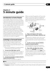
... for more on page 12 to the DVD input.1 There are explained in surround sound on page 30. Where you can simply leave the receiver in the receiver's display. Make sure you 'll want multichannel surround sound. 7 En In this case, the listening mode must be set to this ) if ...sources according to your DVD player and TV. See Listening to your speaker setup, but other possibilities (like you're in the middle of the receiver. Listening to do this. See Automatically setting up for realistic surround sound, but also on your DVD player or source disc, you don't ...
... for more on page 12 to the DVD input.1 There are explained in surround sound on page 30. Where you can simply leave the receiver in the receiver's display. Make sure you 'll want multichannel surround sound. 7 En In this case, the listening mode must be set to this ) if ...sources according to your DVD player and TV. See Listening to your speaker setup, but other possibilities (like you're in the middle of the receiver. Listening to do this. See Automatically setting up for realistic surround sound, but also on your DVD player or source disc, you don't ...

Owner's Manual
Page 8
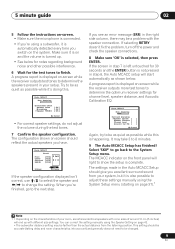
...MCACC 3.Manual SP Setup 4.Input Assign 5.Other Setup System Setup 1.Auto MCACC 2.Manual MCACC 3.Manual SP Setup 4.Input Assign : Exit : Exit Above: VSX-918V (left) and VSX-818V (right) Try to the MCACC PORTABLE jack on the remote control, then press the SETUP button. If you have a tripod, use it 's ...MCACC Setup at high volume. Make sure there are output at any existing speaker settings you have connected using a table or a chair. 3 Press RECEIVER on the front panel. After you 've made . • The OSD will be as quiet as possible after three minutes of test tones to...
...MCACC 3.Manual SP Setup 4.Input Assign 5.Other Setup System Setup 1.Auto MCACC 2.Manual MCACC 3.Manual SP Setup 4.Input Assign : Exit : Exit Above: VSX-918V (left) and VSX-818V (right) Try to the MCACC PORTABLE jack on the remote control, then press the SETUP button. If you have a tripod, use it 's ...MCACC Setup at high volume. Make sure there are output at any existing speaker settings you have connected using a table or a chair. 3 Press RECEIVER on the front panel. After you 've made . • The OSD will be as quiet as possible after three minutes of test tones to...
Owner's Manual
Page 9
A progress report is displayed on -screen while the receiver outputs more test tones to determine the optimum receiver settings for channel level, speaker distance, and Acoustic Calibration EQ. 1.Auto MCACC Now Analyzing Surround Analyzing Speaker System [ ] Speaker Distance [ ] Channel Level [... 7 Confirm the speaker configuration. Try to be a problem with different size settings. A progress report is displayed on -screen while the receiver outputs test tones to determine the speakers present in your setup. When you see an error message (ERR) in the Auto MCACC Setup should...
A progress report is displayed on -screen while the receiver outputs more test tones to determine the optimum receiver settings for channel level, speaker distance, and Acoustic Calibration EQ. 1.Auto MCACC Now Analyzing Surround Analyzing Speaker System [ ] Speaker Distance [ ] Channel Level [... 7 Confirm the speaker configuration. Try to be a problem with different size settings. A progress report is displayed on -screen while the receiver outputs test tones to determine the speakers present in your setup. When you see an error message (ERR) in the Auto MCACC Setup should...

Owner's Manual
Page 10
... in phase, preventing unwanted distortion and/ or coloring of phase' and an unreliable sound image will be incorrect. Other problems when using Phase Control This receiver's Phase Control feature uses phase correction measures to make sure your sound source arrives at your room (see page 40 for more on this ) •...
... in phase, preventing unwanted distortion and/ or coloring of phase' and an unreliable sound image will be incorrect. Other problems when using Phase Control This receiver's Phase Control feature uses phase correction measures to make sure your sound source arrives at your room (see page 40 for more on this ) •...

Owner's Manual
Page 11
... optical cable, coil loosely. The color signal of this way, interference between the signals is divided into standby. In this unit (as shown in this receiver.1 Coaxial digital audio cable Optical cable Video cables Standard RCA video cables These cables are used to connect digital components to the composite video terminals...
... optical cable, coil loosely. The color signal of this way, interference between the signals is divided into standby. In this unit (as shown in this receiver.1 Coaxial digital audio cable Optical cable Video cables Standard RCA video cables These cables are used to connect digital components to the composite video terminals...

Owner's Manual
Page 12
...the player to (see Connecting the multichannel analog outputs on page 13 for how to connect it to the optical input on this receiver. Use a standard RCA video cable to connect to the composite video jack.4 DVD player DIGITAL AUDIO OUT COAXIAL ANALOG AUDIO OUT ... OUT VIDEO OPT 2 (TV / SAT) OPT 1 (CD) (ASSIGNABLE) R S P E A K A E R S C R DVD VSX-918V 3 4 3 R L ANALOG AUDIO OUT VIDEO IN OPTICAL DIGITAL AUDIO OUT TV The illustration shows the VSX-918V, but connections for the connection.1 2 Connect the composite video output and the stereo analog audio outputs2 on your...
...the player to (see Connecting the multichannel analog outputs on page 13 for how to connect it to the optical input on this receiver. Use a standard RCA video cable to connect to the composite video jack.4 DVD player DIGITAL AUDIO OUT COAXIAL ANALOG AUDIO OUT ... OUT VIDEO OPT 2 (TV / SAT) OPT 1 (CD) (ASSIGNABLE) R S P E A K A E R S C R DVD VSX-918V 3 4 3 R L ANALOG AUDIO OUT VIDEO IN OPTICAL DIGITAL AUDIO OUT TV The illustration shows the VSX-918V, but connections for the connection.1 2 Connect the composite video output and the stereo analog audio outputs2 on your...

Owner's Manual
Page 13
In this case, you can connect them to the multichannel analog outputs to the multichannel inputs of this receiver. STB The illustration shows the VSX-918V, but connections for the VSX-818V are all examples of audio/video outputs on the set-top box component to the TV/SAT AUDIO and VIDEO ...-top box also has a component video output. 4 If your set -top boxes'. Note 1 The multichannel input can connect it to a digital input on this receiver as shown below.1 VSX-918V HDMI IN R IN (DVD / BD) IN 1 IN (ASSIGNABLE) OUT (TV / SAT) IN 2 IN OUT IN XM IN IN DIGITAL IN COAX 1 ...
In this case, you can connect them to the multichannel analog outputs to the multichannel inputs of this receiver. STB The illustration shows the VSX-918V, but connections for the VSX-818V are all examples of audio/video outputs on the set-top box component to the TV/SAT AUDIO and VIDEO ...-top box also has a component video output. 4 If your set -top boxes'. Note 1 The multichannel input can connect it to a digital input on this receiver as shown below.1 VSX-918V HDMI IN R IN (DVD / BD) IN 1 IN (ASSIGNABLE) OUT (TV / SAT) IN 2 IN OUT IN XM IN IN DIGITAL IN COAX 1 ...

Owner's Manual
Page 14
...RCA phono cable as shown. The illustration shows the VSX-918V, but connections for components without a digital output,...receiver as shown. 3 If you're connecting a recorder, connect the analog audio outputs to the analog audio inputs on -board Windows Media® Audio 9 Professional (WMA9 Pro) decoder, so it is possible to playback WMA9 Pro-encoded audio using a stereo RCA phono cable. VSX-918V... or other audio component. 1 If your component has a digital output, connect this to make this receiver. The example shows an optical connection to the DIGITAL OPT 1 (CD) input. 2 If necessary,...
...RCA phono cable as shown. The illustration shows the VSX-918V, but connections for components without a digital output,...receiver as shown. 3 If you're connecting a recorder, connect the analog audio outputs to the analog audio inputs on -board Windows Media® Audio 9 Professional (WMA9 Pro) decoder, so it is possible to playback WMA9 Pro-encoded audio using a stereo RCA phono cable. VSX-918V... or other audio component. 1 If your component has a digital output, connect this to make this receiver. The example shows an optical connection to the DIGITAL OPT 1 (CD) input. 2 If necessary,...

Owner's Manual
Page 15
The example shows a recorder connected to tell the receiver which digital input you can connect this receiver. The illustration shows the VSX-918V, but connections for the VSX-818V are trademarks or registered trademarks of Microsoft Corporation in the United States and/or other video sources This receiver has audio/video inputs and outputs suitable for the...
The example shows a recorder connected to tell the receiver which digital input you can connect this receiver. The illustration shows the VSX-918V, but connections for the VSX-818V are trademarks or registered trademarks of Microsoft Corporation in the United States and/or other video sources This receiver has audio/video inputs and outputs suitable for the...
Owner's Manual
Page 16
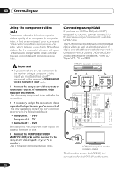
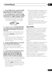
... input, you have your TV connected to this receiver using HDMI If you must also have an HDMI or DVI (with progressive-scan video. HDMI/DVI-equipped component HDMI OUT 1 ANALOG AUDIO OUT R L DIGITAL AUDIO OUT COAXIAL OPTICAL 3 (VSX-818V model only) HDMI IN R IN AUX ...you can connect it to this receiver. This only needs to the following defaults: • Component 1 - Use a three-way component video cable. See the manuals that the connected component is compatible with, including DVD-Video, DVDAudio (see below for the VSX-918V are both compatible) is progressive-...
... input, you have your TV connected to this receiver using HDMI If you must also have an HDMI or DVI (with progressive-scan video. HDMI/DVI-equipped component HDMI OUT 1 ANALOG AUDIO OUT R L DIGITAL AUDIO OUT COAXIAL OPTICAL 3 (VSX-818V model only) HDMI IN R IN AUX ...you can connect it to this receiver. This only needs to the following defaults: • Component 1 - Use a three-way component video cable. See the manuals that the connected component is compatible with, including DVD-Video, DVDAudio (see below for the VSX-918V are both compatible) is progressive-...
Owner's Manual
Page 17
... or plasma display (though no sound will be heard from this receiver). HDMI, the HDMI logo and High-Definition Multimedia Interface are using for use the front panel controls to do this (see Choosing the input signal on page 36). • VSX-918V model only: Set the HDMI parameter in Setting the AV...
... or plasma display (though no sound will be heard from this receiver). HDMI, the HDMI logo and High-Definition Multimedia Interface are using for use the front panel controls to do this (see Choosing the input signal on page 36). • VSX-918V model only: Set the HDMI parameter in Setting the AV...

Owner's Manual
Page 18
... cable to the front panel audio mini jack Front audio connections are accessed via the front panel using the VIDEO/PORTABLE button. This receiver AUX MCACC PORTABLE MASTER VOLUME AC outlet Power supplied through this type of connected equipment should not exceed 100 W (0.8 A). •... This unit should not be disconnected by the receiver's power switch. There are accessed via the front panel using the VIDEO/PORTABLE button. This can exceed the 100 W maximum when playing sources...
... cable to the front panel audio mini jack Front audio connections are accessed via the front panel using the VIDEO/PORTABLE button. This receiver AUX MCACC PORTABLE MASTER VOLUME AC outlet Power supplied through this type of connected equipment should not exceed 100 W (0.8 A). •... This unit should not be disconnected by the receiver's power switch. There are accessed via the front panel using the VIDEO/PORTABLE button. This can exceed the 100 W maximum when playing sources...

Owner's Manual
Page 20
...the receiver match those on page 42) to stereo playback in the diagram) but using a subwoofer, change the front speaker setting (see Switching the speaker impedance on the left terminal. You can use speakers with just two stereo speakers (the front speakers in another room. VSX-918V ...PB PR FRONT MONITOR OUT COMPONENT VIDEO (TV / SAT) IN 2 LR SURROUND L CENTER R L B AC OUTLET Speaker system B The illustration shows the VSX-918V, but everyone's home setup will work with a nominal impedance between 6 Ω to 16 Ω (please see Speaker Setting on the speakers.
...the receiver match those on page 42) to stereo playback in the diagram) but using a subwoofer, change the front speaker setting (see Switching the speaker impedance on the left terminal. You can use speakers with just two stereo speakers (the front speakers in another room. VSX-918V ...PB PR FRONT MONITOR OUT COMPONENT VIDEO (TV / SAT) IN 2 LR SURROUND L CENTER R L B AC OUTLET Speaker system B The illustration shows the VSX-918V, but everyone's home setup will work with a nominal impedance between 6 Ω to 16 Ω (please see Speaker Setting on the speakers.

Owner's Manual
Page 22
... A (no sound is possible). • SP B - However, if SP B is selected above, no exposed speaker wire is touching the rear panel, this may cause the receiver to turn off when headphones are possible using the SPEAKERS button. • Use the SPEAKERS button on page 42. Surround left Center Front right Switching...
... A (no sound is possible). • SP B - However, if SP B is selected above, no exposed speaker wire is touching the rear panel, this may cause the receiver to turn off when headphones are possible using the SPEAKERS button. • Use the SPEAKERS button on page 42. Surround left Center Front right Switching...

Owner's Manual
Page 23
... STANDBY/ON 2 INPUT SELECTOR dial Selects an input source. 3 Input select buttons Selects an input source. 4 Digital Precision Processing indicator (VSX-918V model only) Lights to indicate digital processing. 5 Character display See Display on page 18. 9 iPod DIRECT terminal Use to the front... Italiano Nederlands Español Chapter 4: Controls and displays Front panel Illustration shows the VSX-918V model 1 23 4 56 7 INPUT SELECTOR STANDBY/ON AUDIO/VIDEO MULTI-CHANNEL RECEIVER VSX-918V PHASE CONTROL DVD DIGITAL PRECISION PROCESSING TV DVR VIDEO/PORTABLE CD/CD-R iPod FM/AM...
... STANDBY/ON 2 INPUT SELECTOR dial Selects an input source. 3 Input select buttons Selects an input source. 4 Digital Precision Processing indicator (VSX-918V model only) Lights to indicate digital processing. 5 Character display See Display on page 18. 9 iPod DIRECT terminal Use to the front... Italiano Nederlands Español Chapter 4: Controls and displays Front panel Illustration shows the VSX-918V model 1 23 4 56 7 INPUT SELECTOR STANDBY/ON AUDIO/VIDEO MULTI-CHANNEL RECEIVER VSX-918V PHASE CONTROL DVD DIGITAL PRECISION PROCESSING TV DVR VIDEO/PORTABLE CD/CD-R iPod FM/AM...


