Owner's Manual
Page 4
.... 01 Important User Guidance Information 02 Safety Precautions 03 Supplied Accessories Identifying the main units 12 Plasma Display 12 Media Receiver 12 04 Part Names Plasma Display 13 Media Receiver 14 Remote control unit 16 Setting MTS/SAP mode 28 Viewing a channel banner 29 Using the POD service 29 Using the multiscreen functions 29 Splitting the screen 29 Freezing images 30 07 TV Guide On Screen™ System Setup About the TV Guide On Screen™ system...
.... 01 Important User Guidance Information 02 Safety Precautions 03 Supplied Accessories Identifying the main units 12 Plasma Display 12 Media Receiver 12 04 Part Names Plasma Display 13 Media Receiver 14 Remote control unit 16 Setting MTS/SAP mode 28 Viewing a channel banner 29 Using the POD service 29 Using the multiscreen functions 29 Splitting the screen 29 Freezing images 30 07 TV Guide On Screen™ System Setup About the TV Guide On Screen™ system...
Owner's Manual
Page 5
... Displaying a DVD image 68 Scheduling recordings and reminders ... 54 Watching a VCR image 68 The Schedule Options menu 55 Connecting a VCR 68 Changing setup options 55 Displaying a VCR image 68 Changing the System Settings 55 Using HDMI Input 69 Changing the Channel Display Connecting HDMI equipment 69 settings 56 Enjoying a game console or watching Changing the Default Options 57 camcorder images 70 11 Adjustments and Settings Sleep Timer 58 AV Selection 58 Basic picture adjustments 59 Advanced picture adjustments 60 Using PureCinema 60 Using Color Temp...
... Displaying a DVD image 68 Scheduling recordings and reminders ... 54 Watching a VCR image 68 The Schedule Options menu 55 Connecting a VCR 68 Changing setup options 55 Displaying a VCR image 68 Changing the System Settings 55 Using HDMI Input 69 Changing the Channel Display Connecting HDMI equipment 69 settings 56 Enjoying a game console or watching Changing the Default Options 57 camcorder images 70 11 Adjustments and Settings Sleep Timer 58 AV Selection 58 Basic picture adjustments 59 Advanced picture adjustments 60 Using PureCinema 60 Using Color Temp...
Owner's Manual
Page 7
... User Guidance Information In order to this rule. To achieve images of exceptional quality, this information carefully. The Pioneer PureVision PRO-1130HD/PRO-930HD incorporates the latest in order to "STANDBY" mode. Direct Color Filter. This improves the color / picture reproduction of time, when using only parts and accessories designed by using a vacuum cleaner set to come, please carefully read this Pioneer Plasma Display System incorporates state-of a high quality Plasma Display...
... User Guidance Information In order to this rule. To achieve images of exceptional quality, this information carefully. The Pioneer PureVision PRO-1130HD/PRO-930HD incorporates the latest in order to "STANDBY" mode. Direct Color Filter. This improves the color / picture reproduction of time, when using only parts and accessories designed by using a vacuum cleaner set to come, please carefully read this Pioneer Plasma Display System incorporates state-of a high quality Plasma Display...
Owner's Manual
Page 10
... and/or short internal parts. When the power cord or plug is not designed for example, by the manufacturer. 21. e. f. Never expose the screen of inadequate attachments can block ventilation openings. Cleaning-Unplug the power cord from the AC outlet before installing the speakers. 23. Use of the Plasma Display to follow the manufacturer's instructions. Use only a cart, stand, tripod, bracket or table recommended by the manufacturer...
... and/or short internal parts. When the power cord or plug is not designed for example, by the manufacturer. 21. e. f. Never expose the screen of inadequate attachments can block ventilation openings. Cleaning-Unplug the power cord from the AC outlet before installing the speakers. 23. Use of the Plasma Display to follow the manufacturer's instructions. Use only a cart, stand, tripod, bracket or table recommended by the manufacturer...

Owner's Manual
Page 15
Part Names 04 Rear view 1 23 4 5 6 7 8 MONITOR OUT ANT/ CABLE A IN INPUT 2 G-LINK INPUT 3 S400 (TS) R-AUDIO-L OPTICAL DIGITAL OUT SUB WOOFER Cable CARD I N OUT CONTROL ANT B IN SERVICE ONLY R-AUDIO-L VIDEO S-VIDEO INPUT 1 Y CB / PB COMPONENT VIDEO CR / PR INPUT 1 INPUT 3 HDMI BLACK WHITE SYSTEM CABLE AC IN 17 9 10 11 12 13 14 1516 18 19 20 21 1 ANT/CABLE A IN terminal 2 MONITOR OUT terminals (AUDIO) 3 MONITOR OUT terminal (VIDEO) 4 G-LINK terminal 5 i.LINK terminals 6 SUB WOOFER terminal 7 DIGITAL OUT terminal...
Part Names 04 Rear view 1 23 4 5 6 7 8 MONITOR OUT ANT/ CABLE A IN INPUT 2 G-LINK INPUT 3 S400 (TS) R-AUDIO-L OPTICAL DIGITAL OUT SUB WOOFER Cable CARD I N OUT CONTROL ANT B IN SERVICE ONLY R-AUDIO-L VIDEO S-VIDEO INPUT 1 Y CB / PB COMPONENT VIDEO CR / PR INPUT 1 INPUT 3 HDMI BLACK WHITE SYSTEM CABLE AC IN 17 9 10 11 12 13 14 1516 18 19 20 21 1 ANT/CABLE A IN terminal 2 MONITOR OUT terminals (AUDIO) 3 MONITOR OUT terminal (VIDEO) 4 G-LINK terminal 5 i.LINK terminals 6 SUB WOOFER terminal 7 DIGITAL OUT terminal...
Owner's Manual
Page 16
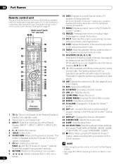
... program listing screen vertically. • When using the TV Guide On Screen™ System, starts recording with "TV" selected) 12 10 INFO: Displays a channel banner when a TV program is in operation, displays information about 5 seconds. 9 24 This button is displayed. 31 (REC): When using the remote control unit, point it into standby mode. 27 DISPLAY: Displays the channel information. 2 Transmission confirmation LED 28 SCREEN SIZE: Selects the screen size. 3 INPUT: Selects an input source of the Plasma 29 SLEEP: Sets...
... program listing screen vertically. • When using the TV Guide On Screen™ System, starts recording with "TV" selected) 12 10 INFO: Displays a channel banner when a TV program is in operation, displays information about 5 seconds. 9 24 This button is displayed. 31 (REC): When using the remote control unit, point it into standby mode. 27 DISPLAY: Displays the channel information. 2 Transmission confirmation LED 28 SCREEN SIZE: Selects the screen size. 3 INPUT: Selects an input source of the Plasma 29 SLEEP: Sets...
Owner's Manual
Page 23
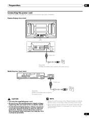
... supply voltage; Plasma Display (rear view) SYSTEM CABLE WHITE BLACK SYSTEM CABLE WHITE BLACK Power cord Noise filter Partially eliminates noise caused by the power source. protection. Preparation 05 Connecting the power cord Connect the power cord after all component connections have been completed. Media Receiver (rear view) MONITOR OUT ANT/ CABLE A IN INPUT 2 G-LINK INPUT 3 S400 (TS) R-AUDIO-L OPTICAL DIGITAL OUT SUB WOOFER Cable CARD I N OUT CONTROL ANT B IN SERVICE ONLY R-AUDIO-L VIDEO S-VIDEO INPUT 1 Y CB / PB COMPONENT VIDEO CR / PR INPUT 1 INPUT 3 HDMI BLACK...
... supply voltage; Plasma Display (rear view) SYSTEM CABLE WHITE BLACK SYSTEM CABLE WHITE BLACK Power cord Noise filter Partially eliminates noise caused by the power source. protection. Preparation 05 Connecting the power cord Connect the power cord after all component connections have been completed. Media Receiver (rear view) MONITOR OUT ANT/ CABLE A IN INPUT 2 G-LINK INPUT 3 S400 (TS) R-AUDIO-L OPTICAL DIGITAL OUT SUB WOOFER Cable CARD I N OUT CONTROL ANT B IN SERVICE ONLY R-AUDIO-L VIDEO S-VIDEO INPUT 1 Y CB / PB COMPONENT VIDEO CR / PR INPUT 1 INPUT 3 HDMI BLACK...
Owner's Manual
Page 25
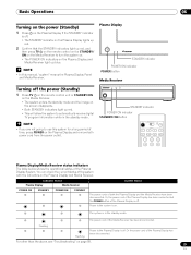
... been connected but the POWER button of the Plasma Display System. Plasma Display STANDBY indicator POWER ON indicator POWER button Media Receiver Turning off the power (Standby) 1 Press TV a on the remote control unit or STANDBY/ON on the Media Receiver. • The system enters the standby mode and the image on the Plasma Display and remove both the Plasma Display and the Media Receiver have been disconnected. Power to the system is in the standby mode. The system is on the Plasma Display and Media Receiver light up blue...
... been connected but the POWER button of the Plasma Display System. Plasma Display STANDBY indicator POWER ON indicator POWER button Media Receiver Turning off the power (Standby) 1 Press TV a on the remote control unit or STANDBY/ON on the Media Receiver. • The system enters the standby mode and the image on the Plasma Display and remove both the Plasma Display and the Media Receiver have been disconnected. Power to the system is in the standby mode. The system is on the Plasma Display and Media Receiver light up blue...
Owner's Manual
Page 39
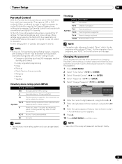
... above TV-G Age-Base TV-PG General audiences Parental guidance suggested . NOTE • Take note of such programs, see pages 41 and 42. Tuner Setup 09 Parental Control With the Parental Control, parents can prevent their children from changing Parental Control settings. TV Parental Guideline Rating System, programs with a rating of "None" may be newly set, using buttons 0 - 9. 7 Enter a 4-digit password to watch a program (or content...
... above TV-G Age-Base TV-PG General audiences Parental guidance suggested . NOTE • Take note of such programs, see pages 41 and 42. Tuner Setup 09 Parental Control With the Parental Control, parents can prevent their children from changing Parental Control settings. TV Parental Guideline Rating System, programs with a rating of "None" may be newly set, using buttons 0 - 9. 7 Enter a 4-digit password to watch a program (or content...
Owner's Manual
Page 46
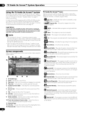
... are displayed horizontally. 4 Time tab - The program is changed to one of Gemstar-TV Guide International, Inc. Records the same channel at the same time/day. • Record Suspend - Indicates the currently selected service. 6 Service bar - Shows information about the highlighted item. 13 Channel ads - NOTE • The TV Guide On Screen™ interactive program guide provides listings for the program. • Record Once - One-time only...
... are displayed horizontally. 4 Time tab - The program is changed to one of Gemstar-TV Guide International, Inc. Records the same channel at the same time/day. • Record Suspend - Indicates the currently selected service. 6 Service bar - Shows information about the highlighted item. 13 Channel ads - NOTE • The TV Guide On Screen™ interactive program guide provides listings for the program. • Record Once - One-time only...
Owner's Manual
Page 65
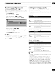
... "Manual Setup". ( / then ENTER) 4 Select an item to exit the menu. PC mode except for all the items, press / to select "Yes", and then press ENTER. A confirmation screen appears. Adjustments and Settings 11 Manual image position and clock adjustments (PC mode only) Usually you can change the parameter using Auto Setup. A side bar appears on some programs. For 14:9 letterbox pictures. For the PRO930HD the number of screen pixels...
... "Manual Setup". ( / then ENTER) 4 Select an item to exit the menu. PC mode except for all the items, press / to select "Yes", and then press ENTER. A confirmation screen appears. Adjustments and Settings 11 Manual image position and clock adjustments (PC mode only) Usually you can change the parameter using Auto Setup. A side bar appears on some programs. For 14:9 letterbox pictures. For the PRO930HD the number of screen pixels...
Owner's Manual
Page 68
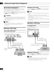
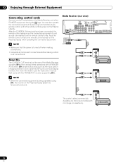
... coming from the power outlet before making connections. MONITOR OUT ANT/ CABLE A IN INPUT 2 G-LINK INPUT 3 S400 (TS) R-AUDIO-L OPTICAL DIGITAL OUT SUB WOOFER Media Receiver (rear view) SERVICE ONLY R-AUDIO-L VIDEO S-VIDEO INPUT 1 Y CB / PB COMPONENT VIDEO CR / PR INPUT 1 HD Displaying a DVD image To watch a VCR image, press INPUT 2 on the remote control unit or press INPUT on the Media Receiver to select INPUT1. CAUTION • To protect all equipment, always unplug the Media Receiver from external equipment, select the input source using the INPUT buttons...
... coming from the power outlet before making connections. MONITOR OUT ANT/ CABLE A IN INPUT 2 G-LINK INPUT 3 S400 (TS) R-AUDIO-L OPTICAL DIGITAL OUT SUB WOOFER Media Receiver (rear view) SERVICE ONLY R-AUDIO-L VIDEO S-VIDEO INPUT 1 Y CB / PB COMPONENT VIDEO CR / PR INPUT 1 HD Displaying a DVD image To watch a VCR image, press INPUT 2 on the remote control unit or press INPUT on the Media Receiver to select INPUT1. CAUTION • To protect all equipment, always unplug the Media Receiver from external equipment, select the input source using the INPUT buttons...
Owner's Manual
Page 69
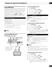
...Auto Automatically identifies input digital video signals. (factory default) Color-1 Digital Component Video signals (4:2:2) locked Color-2 Digital Component Video signals (4:4:4) locked Color-3 Digital RGB signals locked 6 Press HOME MENU to be specified, check the operation manual that results in natural color. • If no image appears, specify another digital video signal type. • For the digital video signal types to exit the menu. Connecting HDMI equipment Media Receiver (rear view) MONITOR OUT ANT/ CABLE A IN INPUT 2 G-LINK INPUT 3 S400 (TS) R-AUDIO-L OPTICAL...
...Auto Automatically identifies input digital video signals. (factory default) Color-1 Digital Component Video signals (4:2:2) locked Color-2 Digital Component Video signals (4:4:4) locked Color-3 Digital RGB signals locked 6 Press HOME MENU to be specified, check the operation manual that results in natural color. • If no image appears, specify another digital video signal type. • For the digital video signal types to exit the menu. Connecting HDMI equipment Media Receiver (rear view) MONITOR OUT ANT/ CABLE A IN INPUT 2 G-LINK INPUT 3 S400 (TS) R-AUDIO-L OPTICAL...
Owner's Manual
Page 71
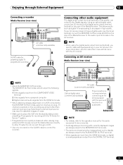
... the display are always output to the SUBWOOFER OUTPUT terminal. • When signals are input from the HDMI terminals, no digital or analog signals are output from the HDMI terminals • When watching images played back on a VCR connected to the MONITOR OUT terminals, select an input source (e.g., TV channel reception) on the recording equipment other than external input sources. Using an optical digital cable, connect an AV receiver to the digital audio output terminal (optical) on the rear of the Media Receiver...
... the display are always output to the SUBWOOFER OUTPUT terminal. • When signals are input from the HDMI terminals, no digital or analog signals are output from the HDMI terminals • When watching images played back on a VCR connected to the MONITOR OUT terminals, select an input source (e.g., TV channel reception) on the recording equipment other than external input sources. Using an optical digital cable, connect an AV receiver to the digital audio output terminal (optical) on the rear of the Media Receiver...
Owner's Manual
Page 72
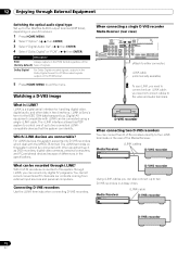
... directly to control one of signals. i.LINK is a digital serial interface for handling digital video, digital audio, and other equipment such as DVD recorders, digital video cameras, personal computers, and PC peripheral devices because of the Media Receiver. When connecting a single D-VHS recorder Media Receiver (rear view) MONITOR OUT ANT/ CABLE A IN INPUT 2 G-LINK INPUT 3 S400 (TS) R-AUDIO-L OPTICAL DIGITAL OUT SUB WOOFER Cable CARD NT B N SERVICE ONLY R-AUDIO-L VIDEO S-VIDEO INPUT 1 Y CB / PB COMPONENT VIDEO CR / PR INPUT 1 INPUT 3 HDMI BLACK SYSTEM CABL (Attach...
... directly to control one of signals. i.LINK is a digital serial interface for handling digital video, digital audio, and other equipment such as DVD recorders, digital video cameras, personal computers, and PC peripheral devices because of the Media Receiver. When connecting a single D-VHS recorder Media Receiver (rear view) MONITOR OUT ANT/ CABLE A IN INPUT 2 G-LINK INPUT 3 S400 (TS) R-AUDIO-L OPTICAL DIGITAL OUT SUB WOOFER Cable CARD NT B N SERVICE ONLY R-AUDIO-L VIDEO S-VIDEO INPUT 1 Y CB / PB COMPONENT VIDEO CR / PR INPUT 1 INPUT 3 HDMI BLACK SYSTEM CABL (Attach...
Owner's Manual
Page 73
... that support i.LINK cannot relay data when their power is off. • Do not make the following loop connections: Media Receiver REC ON STANDBY TIMER STANDBY/ON D-VHS recorder PULL OPEN D-VHS recorder Media Receiver STANDBY/ON REC ON STANDBY TIMER PULL OPEN D-VHS recorder Displaying a D-VHS image To watch a D-VHS image, press i.LINK on the remote control unit or press INPUT on the Media Receiver to select i.LINK. You cannot use...
... that support i.LINK cannot relay data when their power is off. • Do not make the following loop connections: Media Receiver REC ON STANDBY TIMER STANDBY/ON D-VHS recorder PULL OPEN D-VHS recorder Media Receiver STANDBY/ON REC ON STANDBY TIMER PULL OPEN D-VHS recorder Displaying a D-VHS image To watch a D-VHS image, press i.LINK on the remote control unit or press INPUT on the Media Receiver to select i.LINK. You cannot use...
Owner's Manual
Page 75
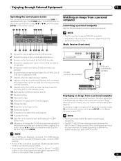
... the standby mode. 10 Switches the D-VHS recorder on the Media Receiver to use Auto Setup. HOME GALLERY PC CARD SLOT Y CB / PB CR / PR COMPONENT VIDEO EJECT S-VIDEO VIDEO INPUT 4 L AUDIO R PC ANALOG RGB PC AV cable (commercially available) RGB cable (commercially available) Personal computer Displaying an image from the list, and then press ENTER. appears. To select a button on the control panel screen, press / or / , and then press ENTER on the remote control...
... the standby mode. 10 Switches the D-VHS recorder on the Media Receiver to use Auto Setup. HOME GALLERY PC CARD SLOT Y CB / PB CR / PR COMPONENT VIDEO EJECT S-VIDEO VIDEO INPUT 4 L AUDIO R PC ANALOG RGB PC AV cable (commercially available) RGB cable (commercially available) Personal computer Displaying an image from the list, and then press ENTER. appears. To select a button on the control panel screen, press / or / , and then press ENTER on the remote control...
Owner's Manual
Page 77
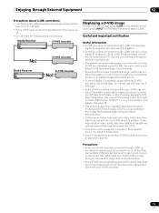
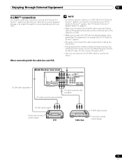
... the standby status when presetting TV programs for the TV Guide On Screen™ system. G-LINK cable (supplied) Media Receiver (rear view) MONITOR OUT ANT/ CABLE A IN INPUT 2 G-LINK INPUT 3 S400 (TS) R-AUDIO-L OPTICAL DIGITAL OUT SUB WOOFER Cable CAR I N OUT CONTROL ANT B IN SERVICE ONLY R-AUDIO-L VIDEO S-VIDEO INPUT 1 Y CB / PB COMPONENT VIDEO CR / PR INPUT 1 INPUT 3 HDMI AV cable (commercially available) AV cable (commercially available) G-LINK cable's wand Point to the remote control sensor VCR Cable box G-LINK cable's wand Point to correctly set up...
... the standby status when presetting TV programs for the TV Guide On Screen™ system. G-LINK cable (supplied) Media Receiver (rear view) MONITOR OUT ANT/ CABLE A IN INPUT 2 G-LINK INPUT 3 S400 (TS) R-AUDIO-L OPTICAL DIGITAL OUT SUB WOOFER Cable CAR I N OUT CONTROL ANT B IN SERVICE ONLY R-AUDIO-L VIDEO S-VIDEO INPUT 1 Y CB / PB COMPONENT VIDEO CR / PR INPUT 1 INPUT 3 HDMI AV cable (commercially available) AV cable (commercially available) G-LINK cable's wand Point to the remote control sensor VCR Cable box G-LINK cable's wand Point to correctly set up...
Owner's Manual
Page 78
... surround mode display function. For more information, see the instruction manual that the power is temporarily reduced. After the CONTROL IN terminals have been connected, the remote control sensors on the connected equipment do not accept commands from its remote control unit to the remote control sensor on the rear of the Media Receiver supports SR+, which allows linked operations with a PIONEER AV receiver. Media Receiver (rear view) CONTROL MONITOR OUT ANT/ CABLE A IN INPUT 2 G-LINK INPUT 3 S400 (TS) R-AUDIO-L OPTICAL DIGITAL...
... surround mode display function. For more information, see the instruction manual that the power is temporarily reduced. After the CONTROL IN terminals have been connected, the remote control sensors on the connected equipment do not accept commands from its remote control unit to the remote control sensor on the rear of the Media Receiver supports SR+, which allows linked operations with a PIONEER AV receiver. Media Receiver (rear view) CONTROL MONITOR OUT ANT/ CABLE A IN INPUT 2 G-LINK INPUT 3 S400 (TS) R-AUDIO-L OPTICAL DIGITAL...

Owner's Manual
Page 89
Possible Solution • Make sure the Plasma Display and the Media Receiver are connected correctly. (See page 19.) • Is the power cord disconnected? (See page 23.) • Has the main power been turned on? (See page 25.) • Check if you using a video or PC input source, check that is output. Clean the vents, or remove any button other components correct? (See pages 68 to the...
Possible Solution • Make sure the Plasma Display and the Media Receiver are connected correctly. (See page 19.) • Is the power cord disconnected? (See page 23.) • Has the main power been turned on? (See page 25.) • Check if you using a video or PC input source, check that is output. Clean the vents, or remove any button other components correct? (See pages 68 to the...


