Technical Manual
Page 1
... MOUNTING/INSTALLATION • This product is a danger that, according to its weight or attachment method, it on the floor, select an adequately stable, flat, and level place. • To prevent damage to change without notice. TECHNICAL MANUAL (Ver. 1.1) FOR PIONEER PLASMA DISPLAY MONITOR WHEN USED WITH VIDEO CARDS (EXPANSION SOLUTIONS CARDS) PLASMA DISPLAY MONITOR: PDP-607CMX VIDEO CARD: PDA-5003 / PDA-5004 TABLE TOP STAND: PDK-TS26 WALL MOUNT UNIT: PDK-WM03 SPEAKER SYSTEM: PDP-S55-LR This manual...
... MOUNTING/INSTALLATION • This product is a danger that, according to its weight or attachment method, it on the floor, select an adequately stable, flat, and level place. • To prevent damage to change without notice. TECHNICAL MANUAL (Ver. 1.1) FOR PIONEER PLASMA DISPLAY MONITOR WHEN USED WITH VIDEO CARDS (EXPANSION SOLUTIONS CARDS) PLASMA DISPLAY MONITOR: PDP-607CMX VIDEO CARD: PDA-5003 / PDA-5004 TABLE TOP STAND: PDK-TS26 WALL MOUNT UNIT: PDK-WM03 SPEAKER SYSTEM: PDP-S55-LR This manual...
Technical Manual
Page 2
...DTV set top box connection 59 4.3.11 Audio connections 60 4.4 Table Top Stand: PDK-TS26 64 4.4.1 Specifications 64 4.4.2 Installation coordinates for screws used to attach the stand to a surface 65 4.4.3 External Dimensions 65 4.4.4 Stand assembling 66 4.4.5 Attaching the Stand to the Plasma Display ....... 67 4.5 Wall Mount Unit: PDK-WM03 68 4.5.1 Specifications 68 4.5.2 External Dimensions 69 4.5.3 Hardware assembly and Plasma Display attachment 70 4.6 Speaker System: PDP-S55-LR 72 4.6.1 Specifications 72 4.6.2 External Dimensions 73 4.6.3 Installation on the Plasma Display 74...
...DTV set top box connection 59 4.3.11 Audio connections 60 4.4 Table Top Stand: PDK-TS26 64 4.4.1 Specifications 64 4.4.2 Installation coordinates for screws used to attach the stand to a surface 65 4.4.3 External Dimensions 65 4.4.4 Stand assembling 66 4.4.5 Attaching the Stand to the Plasma Display ....... 67 4.5 Wall Mount Unit: PDK-WM03 68 4.5.1 Specifications 68 4.5.2 External Dimensions 69 4.5.3 Hardware assembly and Plasma Display attachment 70 4.6 Speaker System: PDP-S55-LR 72 4.6.1 Specifications 72 4.6.2 External Dimensions 73 4.6.3 Installation on the Plasma Display 74...
Technical Manual
Page 5
... one-touch screen adjustment, [AUTO SET UP] function for the connection of external devices, thus enhancing its expansion potential. ¶ Supports wide range of computer signals (analog/digital) This panel supports a wide range of the screen image to adjust the cooling fan's speed with the viewing program and to display important detailed program data. 5 These features include the ability to suppress peak luminance in accordance with changes in at...
... one-touch screen adjustment, [AUTO SET UP] function for the connection of external devices, thus enhancing its expansion potential. ¶ Supports wide range of computer signals (analog/digital) This panel supports a wide range of the screen image to adjust the cooling fan's speed with the viewing program and to display important detailed program data. 5 These features include the ability to suppress peak luminance in accordance with changes in at...

Technical Manual
Page 6
... mm (V) Input/output terminals Video-related INPUT 1 Input Mini D-sub, 15-pin connector (female) • RGB signal (for screen 1 Speed clamp 3 Bead band 3 Operating instructions 1 Warranty 1 Specifications and external designs are subject to change without notice. (NOTE 1) (NOTE 2) (NOTE 3) The display is from AC100 V to 240 V (50 Hz/60 Hz)) In-rush less than 50 A Power factor more than 0.95 Consumption 440 W (NOTE 2) (0.8 W in standby) External dimensions 1470...
... mm (V) Input/output terminals Video-related INPUT 1 Input Mini D-sub, 15-pin connector (female) • RGB signal (for screen 1 Speed clamp 3 Bead band 3 Operating instructions 1 Warranty 1 Specifications and external designs are subject to change without notice. (NOTE 1) (NOTE 2) (NOTE 3) The display is from AC100 V to 240 V (50 Hz/60 Hz)) In-rush less than 50 A Power factor more than 0.95 Consumption 440 W (NOTE 2) (0.8 W in standby) External dimensions 1470...

Technical Manual
Page 10
... button can change the input. 8 SCREEN SIZE (') button Except when menu screen is displayed, this button can change settings. Controls and Connectors 2.3 Controls and Connectors Main unit 3 Main unit Operation panel on -screen menus, these buttons can adjust the sound volume. 0 Functional lock button (concealed button) This button is used to switch between permitted and blocked operation of the control panel and the remote control. The indicator flashes green once per second when the [POWER MGT.] function is operating. When flashing, the light indicates an error...
... button can change the input. 8 SCREEN SIZE (') button Except when menu screen is displayed, this button can change settings. Controls and Connectors 2.3 Controls and Connectors Main unit 3 Main unit Operation panel on -screen menus, these buttons can adjust the sound volume. 0 Functional lock button (concealed button) This button is used to switch between permitted and blocked operation of the control panel and the remote control. The indicator flashes green once per second when the [POWER MGT.] function is operating. When flashing, the light indicates an error...
Technical Manual
Page 11
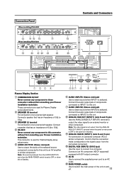
... connected component. 0 DIGITAL RGB (INPUT2) (DVI-D jack) Use this input to connect to obtain sound when INPUT1 is set to OFF or when set to Standby. 567 8 9 0 6 AUDIO (INPUT1) (Stereo mini jack) Use to a computer. Confirm that the connection made corresponds to the signal output from the ANALOG RGB OUT (INPUT1) terminal when the panel's main power is OFF or the panel is selected. This connector is used for Plasma Display setup adjustments. 5 AUDIO (OUTPUT...
... connected component. 0 DIGITAL RGB (INPUT2) (DVI-D jack) Use this input to connect to obtain sound when INPUT1 is set to OFF or when set to Standby. 567 8 9 0 6 AUDIO (INPUT1) (Stereo mini jack) Use to a computer. Confirm that the connection made corresponds to the signal output from the ANALOG RGB OUT (INPUT1) terminal when the panel's main power is OFF or the panel is selected. This connector is used for Plasma Display setup adjustments. 5 AUDIO (OUTPUT...
Technical Manual
Page 15
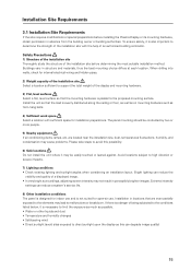
... preparations before determining the most suitable installation method. Bright lighting can degrade image quality) 15 Extreme intensity settings can reduce a system's service life. 8) Other installation conditions The panel is designed for indoor use . Buildings vary in perceptibly brighter images. Installation in locations that are located near the installation site, dust, temperatures fluctuations, humidity, and condensation may cause problems. Please take steps to malfunctions or...
... preparations before determining the most suitable installation method. Bright lighting can degrade image quality) 15 Extreme intensity settings can reduce a system's service life. 8) Other installation conditions The panel is designed for indoor use . Buildings vary in perceptibly brighter images. Installation in locations that are located near the installation site, dust, temperatures fluctuations, humidity, and condensation may cause problems. Please take steps to malfunctions or...
Technical Manual
Page 16
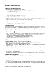
... nearby, remote control function may be affected. The screen's infrared intensity varies, depending upon the displayed image. 16 Characteristics of its functions. When a leakage breaker is installed in electronic equipment. Connect the power cord by ground wires, etc. Significant voltage drop between the circuit panel and the Plasma Display -- Rapid temperature fluctuations can leave water vapor inside switching power sources such as this display receives at the...
... nearby, remote control function may be affected. The screen's infrared intensity varies, depending upon the displayed image. 16 Characteristics of its functions. When a leakage breaker is installed in electronic equipment. Connect the power cord by ground wires, etc. Significant voltage drop between the circuit panel and the Plasma Display -- Rapid temperature fluctuations can leave water vapor inside switching power sources such as this display receives at the...

Technical Manual
Page 44
... line audio, thus increasing the uses for video presentations. ¶ Table Top Stand: PDK-TS26 This vertically installed type onboard stand is a perfect match to the 60-inch Plasma Display. ¶ Wall Mount Unit: PDK-WM03 This wall mount unit is a speaker system designed for conventional displays. This structure simplifies attaching it to the Plasma Display. ¶ Speaker System: PDP-S55-LR This is made for easy mounting. ¶ Video Card: PDA-5003/PDA-5004 The video card...
... line audio, thus increasing the uses for video presentations. ¶ Table Top Stand: PDK-TS26 This vertically installed type onboard stand is a perfect match to the 60-inch Plasma Display. ¶ Wall Mount Unit: PDK-WM03 This wall mount unit is a speaker system designed for conventional displays. This structure simplifies attaching it to the Plasma Display. ¶ Speaker System: PDP-S55-LR This is made for easy mounting. ¶ Video Card: PDA-5003/PDA-5004 The video card...

Technical Manual
Page 100
...] button on the remote control or main-control panel during a multi-screen display, the input of Picture-in the menu mode to adjust automatically. Note Muting is cleared when the power is pressed during PC signal input causes the 'SCREEN' in -picture, refer to scroll the display position using the [5/∞/2/3] buttons on the remote control. 7 Multi screen (only when using the remote control) • Pressing the [POINT ZOOM] button on the remote control is turn OFF. 5 Auto screen adjustment • Pressing the [AUTO SET...
...] button on the remote control or main-control panel during a multi-screen display, the input of Picture-in the menu mode to adjust automatically. Note Muting is cleared when the power is pressed during PC signal input causes the 'SCREEN' in -picture, refer to scroll the display position using the [5/∞/2/3] buttons on the remote control. 7 Multi screen (only when using the remote control) • Pressing the [POINT ZOOM] button on the remote control is turn OFF. 5 Auto screen adjustment • Pressing the [AUTO SET...

Technical Manual
Page 123
... 123 Screen 2 MENU PICTURE SCREEN C O L O R T E M P. Settable condition: When there is pressed, the setting changes as movies that can be selected differ. The PURECINEMA setting should be performed for each input (INPUT1 to a progressive video signal by a 2-3 pull-down process. AUTO POWER OFF DNR MPEG NR CTI PURECINEMA COLOR DECODING COLOR SYSTEM SIGNAL FORMAT SET ENTER INPUT1 SETUP OPTION :MIDDLE :DISABLE :MIDDLE :LOW :ON :OFF :RGB :AUTO MENU EXIT 3 Each time a [2/3] button is video signal input Factory setting...
... 123 Screen 2 MENU PICTURE SCREEN C O L O R T E M P. Settable condition: When there is pressed, the setting changes as movies that can be selected differ. The PURECINEMA setting should be performed for each input (INPUT1 to a progressive video signal by a 2-3 pull-down process. AUTO POWER OFF DNR MPEG NR CTI PURECINEMA COLOR DECODING COLOR SYSTEM SIGNAL FORMAT SET ENTER INPUT1 SETUP OPTION :MIDDLE :DISABLE :MIDDLE :LOW :ON :OFF :RGB :AUTO MENU EXIT 3 Each time a [2/3] button is video signal input Factory setting...

Technical Manual
Page 125
... example, digital tuner, etc. This setting must comply with DVI output port RGB video output of Y/Cb/Cr format. Connected component SETUP Component video output of a PC COLOR DECODING COMP.1 COMP.2 RGB RGB Not supported Screen 2 MENU PICTURE SCREEN C O L O R T E M P. AUTO POWER OFF DNR MPEG NR CTI PURECINEMA COLOR DECODING COLOR SYSTEM SIGNAL FORMAT SET CHANGE INPUT1 SETUP OPTION :MIDDLE :DISABLE :MIDDLE :LOW :ON :OFF :RGB :AUTO MENU EXIT 125 Settable condition: Factory setting: INPUT1, INPUT2, INPUT5 When a video signal (signal other than a PC signal) is input at...
... example, digital tuner, etc. This setting must comply with DVI output port RGB video output of Y/Cb/Cr format. Connected component SETUP Component video output of a PC COLOR DECODING COMP.1 COMP.2 RGB RGB Not supported Screen 2 MENU PICTURE SCREEN C O L O R T E M P. AUTO POWER OFF DNR MPEG NR CTI PURECINEMA COLOR DECODING COLOR SYSTEM SIGNAL FORMAT SET CHANGE INPUT1 SETUP OPTION :MIDDLE :DISABLE :MIDDLE :LOW :ON :OFF :RGB :AUTO MENU EXIT 125 Settable condition: Factory setting: INPUT1, INPUT2, INPUT5 When a video signal (signal other than a PC signal) is input at...

Technical Manual
Page 130
Menu Mode [Applicable only when a PDA-5003/PDA-5004 is installed] 11) Menu Language Display Setting The factory setting for both inputs. 130 Factory setting: ENGLISH 1 Select 'OPTION'. 2 Place the cursor over 'LANGUAGE' then press the [SET] button. Screen 3 Note LANGUAGE SET SET : FRANÇAIS MENU EXIT When the screen display language is set for either INPUT1 to change the setting. To change to another language it is necessary to INPUT5, the same...
Menu Mode [Applicable only when a PDA-5003/PDA-5004 is installed] 11) Menu Language Display Setting The factory setting for both inputs. 130 Factory setting: ENGLISH 1 Select 'OPTION'. 2 Place the cursor over 'LANGUAGE' then press the [SET] button. Screen 3 Note LANGUAGE SET SET : FRANÇAIS MENU EXIT When the screen display language is set for either INPUT1 to change the setting. To change to another language it is necessary to INPUT5, the same...

Technical Manual
Page 142
... Zoom or multi-screen display, follow the instructions under 1) Entering the Integrator Mode. 142 When a new ninth type of input signal is adjusted, the adjustment data for the oldest input signal is deleted. • For details, refer to section 5.4.4, "PICTURE, White Balance and SCREEN Position Adjustment Values Memory Area Tables" (pg. 184). 4) Exiting the integrator mode • Press the [MENU] button on the remote control or main-control panel to designate to...
... Zoom or multi-screen display, follow the instructions under 1) Entering the Integrator Mode. 142 When a new ninth type of input signal is adjusted, the adjustment data for the oldest input signal is deleted. • For details, refer to section 5.4.4, "PICTURE, White Balance and SCREEN Position Adjustment Values Memory Area Tables" (pg. 184). 4) Exiting the integrator mode • Press the [MENU] button on the remote control or main-control panel to designate to...
Technical Manual
Page 150
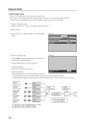
... the remote control or the maincontrol panel to the actual operating condition. 2. Integrator Mode 7) SUB VOLUME Setting This item is for adjusting the audio input level for example a DVD player and a PC. Press the [SET] button to return to match the input with high volume to screen 3. INPUT SELECTOR POWER AMPLIFIER VOLUME Audio block diagram (concept diagram) 150 Screen 3 I N T E G R ATO R INPUT1 PICTURE SCREEN B RT. E N H A N C E SUB VOLUME SETUP OPTION : OFF : 20 SET ENTER MENU EXIT 4 Perform the adjustment. SUB VOLUME (integrator mode): Adjust the input...
... the remote control or the maincontrol panel to the actual operating condition. 2. Integrator Mode 7) SUB VOLUME Setting This item is for adjusting the audio input level for example a DVD player and a PC. Press the [SET] button to return to match the input with high volume to screen 3. INPUT SELECTOR POWER AMPLIFIER VOLUME Audio block diagram (concept diagram) 150 Screen 3 I N T E G R ATO R INPUT1 PICTURE SCREEN B RT. E N H A N C E SUB VOLUME SETUP OPTION : OFF : 20 SET ENTER MENU EXIT 4 Perform the adjustment. SUB VOLUME (integrator mode): Adjust the input...

Technical Manual
Page 154
... pressed, the setting changes as shown below. 3 ON OFF 2 ON ....... Each time a 2/3 button is only effective during INPUT2 and INPUT5 color signal. • Compatible signals: 1080i, 720p, 1080p • It takes about five seconds until display starts. LEVEL, B. LEVEL G. To reduce burning when a black band appears at both edges of a 4:3 image displayed on 'SIDE MASK' then press the [SET] button. LEVEL, G. Screen 3 I N T E G R ATO R INPUT1 PICTURE SCREEN PROGRAM T I MER SCREEN MASK...
... pressed, the setting changes as shown below. 3 ON OFF 2 ON ....... Each time a 2/3 button is only effective during INPUT2 and INPUT5 color signal. • Compatible signals: 1080i, 720p, 1080p • It takes about five seconds until display starts. LEVEL, B. LEVEL G. To reduce burning when a black band appears at both edges of a 4:3 image displayed on 'SIDE MASK' then press the [SET] button. LEVEL, G. Screen 3 I N T E G R ATO R INPUT1 PICTURE SCREEN PROGRAM T I MER SCREEN MASK...

Technical Manual
Page 178
...set by "5.3.4 Adjustments and setting in the Menu Mode: 13) SPLIT FREEZE Setting (pg. 116)", "5.3.7 Adjustments and setting in ( ) represent a case of 16:9 contents. Note It also operates during BANNER PIP. 178 FADE PIP If it is possible to perform fade in -picture. Integrator Mode S BY S SIZE/S BY S LAYOUT Select a SIDE BY SIDE mode display, six options. For details, refer to a signal...341 768 A B *: Numbers in occurs when the sub-screen has changed from no input to "5.5.5 List of the PICTURE IN PICTURE sub-screen. PIP SIZE Select the size of RS-232C Commands (pg. 194)".
...set by "5.3.4 Adjustments and setting in the Menu Mode: 13) SPLIT FREEZE Setting (pg. 116)", "5.3.7 Adjustments and setting in ( ) represent a case of 16:9 contents. Note It also operates during BANNER PIP. 178 FADE PIP If it is possible to perform fade in -picture. Integrator Mode S BY S SIZE/S BY S LAYOUT Select a SIDE BY SIDE mode display, six options. For details, refer to a signal...341 768 A B *: Numbers in occurs when the sub-screen has changed from no input to "5.5.5 List of the PICTURE IN PICTURE sub-screen. PIP SIZE Select the size of RS-232C Commands (pg. 194)".

Technical Manual
Page 196
.... Sets the DVI connection signal to OFF. - TSMS00 + Turns summer time to STB/DVD. TSMS01 + Turns summer time to OFF. ORBS02 + - Sets the ORBITER to ON. - Sets SOFT FOCUS to 1. Sets SOFT FOCUS to OFF. Sets SUB SCREEN FREEZE to PAL M. Saturday New Number direct Last Effective Minimum Maximum memory CLSS06 + + Sets color system to OFF. CLSS07 + + Sets color system to Type9. - - SFTS08 + Sets SIGNAL FORMAT to Type8. - + SFTS09 Sets SIGNAL FORMAT to PAL N. Sets the DVI BLACK...
.... Sets the DVI connection signal to OFF. - TSMS00 + Turns summer time to STB/DVD. TSMS01 + Turns summer time to OFF. ORBS02 + - Sets the ORBITER to ON. - Sets SOFT FOCUS to 1. Sets SOFT FOCUS to OFF. Sets SUB SCREEN FREEZE to PAL M. Saturday New Number direct Last Effective Minimum Maximum memory CLSS06 + + Sets color system to OFF. CLSS07 + + Sets color system to Type9. - - SFTS08 + Sets SIGNAL FORMAT to Type8. - + SFTS09 Sets SIGNAL FORMAT to PAL N. Sets the DVI BLACK...

Technical Manual
Page 208
... PUCS02 VRO Turns off setting. Turns on VIDEO WALL. Sets setting of commands not compatible with PDP-434CMX to normal. Selects audio output fix. Turns on MASK CONTROL. EDIS02 Sets DVI SELECT to FULL 1035i. Sets screen size to VIDEOS1. 208 Sets FRC to "DRE LOW". Sets gradation to MODE2. Starts 232C integrator adjustment mode. Resets still picture movement function. Sets setting of SIDE MASK. Turns on center brightness correction. Displays present MIRROR MODE setting Turns off center brightness correction. Displays present setting of...
... PUCS02 VRO Turns off setting. Turns on VIDEO WALL. Sets setting of commands not compatible with PDP-434CMX to normal. Selects audio output fix. Turns on MASK CONTROL. EDIS02 Sets DVI SELECT to FULL 1035i. Sets screen size to VIDEOS1. 208 Sets FRC to "DRE LOW". Sets gradation to MODE2. Starts 232C integrator adjustment mode. Resets still picture movement function. Sets setting of SIDE MASK. Turns on center brightness correction. Displays present MIRROR MODE setting Turns off center brightness correction. Displays present setting of...
Technical Manual
Page 213
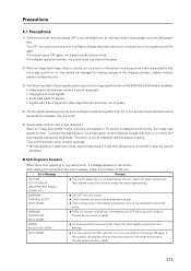
... the problem still persists, remove the power plug from the outlet and contact a Pioneer service center or dealer. 213 To protect the plasma panel, the screen-saver function detects images with a sync signal and video signal that are blocked, remove the obstacles blocking the vents. Check the table of supported input signals on pg. 80 to two minutes then try turning the power ON again. After reading the contents of the error...
... the problem still persists, remove the power plug from the outlet and contact a Pioneer service center or dealer. 213 To protect the plasma panel, the screen-saver function detects images with a sync signal and video signal that are blocked, remove the obstacles blocking the vents. Check the table of supported input signals on pg. 80 to two minutes then try turning the power ON again. After reading the contents of the error...


