Technical Manual
Page 2
...to INPUT2 58 4.3.8 Connection to INPUT3 58 4.3.9 Connection to INPUT4 58 4.3.10 About DTV set top box connection 59 4.3.11 Audio connections 60 4.4 Table Top Stand: PDK-TS26 64 4.4.1 Specifications 64 4.4.2 Installation coordinates for screws used to attach the stand to a...70 4.6 Speaker System: PDP-S55-LR 72 4.6.1 Specifications 72 4.6.2 External Dimensions 73 4.6.3 Installation on the Plasma Display 74 2 BEFORE BEGINNING ADJUSTMENT/SETTING 5.1 Before Beginning Adjustment 78 5.1.1 Operation Mode 78 5.1.2 Combined Use of the Remote Control, Main-control Panel, and RS-232C Commands...
...to INPUT2 58 4.3.8 Connection to INPUT3 58 4.3.9 Connection to INPUT4 58 4.3.10 About DTV set top box connection 59 4.3.11 Audio connections 60 4.4 Table Top Stand: PDK-TS26 64 4.4.1 Specifications 64 4.4.2 Installation coordinates for screws used to attach the stand to a...70 4.6 Speaker System: PDP-S55-LR 72 4.6.1 Specifications 72 4.6.2 External Dimensions 73 4.6.3 Installation on the Plasma Display 74 2 BEFORE BEGINNING ADJUSTMENT/SETTING 5.1 Before Beginning Adjustment 78 5.1.1 Operation Mode 78 5.1.2 Combined Use of the Remote Control, Main-control Panel, and RS-232C Commands...
Technical Manual
Page 4
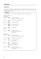
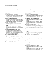
Precautions With the PDA-5003 or the PDA-5004 installed, the PDP-607CMX supports the following functions: Input/output terminals 7 PDA-5003 INPUT 1 Input • Component video signal • RGB signals from AV devices other than PCs... other than PCs INPUT 2 Input • Digital video signal (HDCP supported) INPUT 3 Input • Y/C separate video signal • Audio L/R signal INPUT 4 Input Output • Composite video signal • Audio L/R signal • Composite video signal INPUT 5 Input • Composite video signal • RGB signals from AV devices or PCs •...
Precautions With the PDA-5003 or the PDA-5004 installed, the PDP-607CMX supports the following functions: Input/output terminals 7 PDA-5003 INPUT 1 Input • Component video signal • RGB signals from AV devices other than PCs... other than PCs INPUT 2 Input • Digital video signal (HDCP supported) INPUT 3 Input • Y/C separate video signal • Audio L/R signal INPUT 4 Input Output • Composite video signal • Audio L/R signal • Composite video signal INPUT 5 Input • Composite video signal • RGB signals from AV devices or PCs •...

Technical Manual
Page 6
...RGB signal (DVI compliant TMDS signal) *Microsoft Plug & Play (VESA DDC 2B) supported Audio-related Input AUDIO INPUT (for INPUT1) Stero mini jack L/R 500 mVrms/more than 10 kΩ AUDIO INPUT (for INPUT2) Stero mini jack L/R 500 mVrms/more than two tiers Standard accessories Power...when in original package) Temperature 30 °C to +60 °C (-22 °F to 140 °F) Humidity 20 % to 90 % Atmospheric pressure 700 hPa to "Installation Site Requirements (pg. 15)". 6 Specifications 2.1 Specifications Light-emitting panel 60V type AC Plasma Panel 131.86 cm (W) × 74.19 cm ...
...RGB signal (DVI compliant TMDS signal) *Microsoft Plug & Play (VESA DDC 2B) supported Audio-related Input AUDIO INPUT (for INPUT1) Stero mini jack L/R 500 mVrms/more than 10 kΩ AUDIO INPUT (for INPUT2) Stero mini jack L/R 500 mVrms/more than two tiers Standard accessories Power...when in original package) Temperature 30 °C to +60 °C (-22 °F to 140 °F) Humidity 20 % to 90 % Atmospheric pressure 700 hPa to "Installation Site Requirements (pg. 15)". 6 Specifications 2.1 Specifications Light-emitting panel 60V type AC Plasma Panel 131.86 cm (W) × 74.19 cm ...
Technical Manual
Page 11
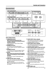
...pin) Use the ANALOG RGB OUT (INPUT1) terminal to output the video signal to these connectors without first consulting your Pioneer installation technician. These connectors are used for Plasma Display setup adjustments. 2 SPEAKER (R) terminal For connection of 6 Ω to 16 Ω. 4 RS-232C Never ...right speaker. Note: No sound is produced from the ANALOG RGB OUT (INPUT1) terminal when the panel's main power is OFF or the panel is used for Plasma Display setup adjustments. 5 AUDIO (OUTPUT) (Stereo mini jack) Use to an AV amplifier or similar component. This connector is ...
...pin) Use the ANALOG RGB OUT (INPUT1) terminal to output the video signal to these connectors without first consulting your Pioneer installation technician. These connectors are used for Plasma Display setup adjustments. 2 SPEAKER (R) terminal For connection of 6 Ω to 16 Ω. 4 RS-232C Never ...right speaker. Note: No sound is produced from the ANALOG RGB OUT (INPUT1) terminal when the panel's main power is OFF or the panel is used for Plasma Display setup adjustments. 5 AUDIO (OUTPUT) (Stereo mini jack) Use to an AV amplifier or similar component. This connector is ...
Technical Manual
Page 12
... jacks) Use this jack to connect components that are connected to obtain sound when INPUT4 is selected. Connect these jacks to the device's audio outputs that the connection corresponds to the signal output from the VIDEO OUT (INPUT4) jack when the display is OFF or in the Standby... computers, external RGB decoders, or components equipped with component output jacks such as a video deck, video camera, laser disc player, or DVD recorder. & AUDIO R/L (INPUT3) (RCA Pin jacks) Use this jack to output the video signal to obtain sound when INPUT3 is selected. VIDEO IN (INPUT4) (BNC jack...
... jacks) Use this jack to connect components that are connected to obtain sound when INPUT4 is selected. Connect these jacks to the device's audio outputs that the connection corresponds to the signal output from the VIDEO OUT (INPUT4) jack when the display is OFF or in the Standby... computers, external RGB decoders, or components equipped with component output jacks such as a video deck, video camera, laser disc player, or DVD recorder. & AUDIO R/L (INPUT3) (RCA Pin jacks) Use this jack to output the video signal to obtain sound when INPUT3 is selected. VIDEO IN (INPUT4) (BNC jack...
Technical Manual
Page 22
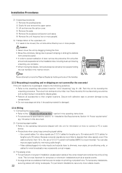
... use of dust, remove the protective film only after all accessories to connect a PC or audio device. • Precautions when using long connecting signal cables -- Because computer signals are not ...• Move the unit slowly, taking care to prevent scraping or striking the delicate front protective panel. • In order to be moved, the unit should always be re-packaged, observe the ...improve signal quality by two or more reliable means. 22 Caution • Never move the Plasma Display by holding the rear handles in this document. 2) Connecting signal cables • Refer...
... use of dust, remove the protective film only after all accessories to connect a PC or audio device. • Precautions when using long connecting signal cables -- Because computer signals are not ...• Move the unit slowly, taking care to prevent scraping or striking the delicate front protective panel. • In order to be moved, the unit should always be re-packaged, observe the ...improve signal quality by two or more reliable means. 22 Caution • Never move the Plasma Display by holding the rear handles in this document. 2) Connecting signal cables • Refer...

Technical Manual
Page 44
... brightness, and image quality, the Plasma Display (PDP-607CMX) is available for conventional displays. It fixes the rear surface of the Plasma Display (PDP607CMX). It is made for the 60-inch Plasma Display. Furthermore, it can handle three line or two line audio, thus increasing the uses for video ...installation holes so it can be mounted in a vertical arrangement. 44 A wide range of standard mounting hardware is thin and lightweight. This panel can be used on different kinds of three lines: a COMPOSITE (1), S INPUT (1), and an analog RGB INPUT or COMPONENT INPUT (1). ...
... brightness, and image quality, the Plasma Display (PDP-607CMX) is available for conventional displays. It fixes the rear surface of the Plasma Display (PDP607CMX). It is made for the 60-inch Plasma Display. Furthermore, it can handle three line or two line audio, thus increasing the uses for video ...installation holes so it can be mounted in a vertical arrangement. 44 A wide range of standard mounting hardware is thin and lightweight. This panel can be used on different kinds of three lines: a COMPOSITE (1), S INPUT (1), and an analog RGB INPUT or COMPONENT INPUT (1). ...

Technical Manual
Page 46
.... • Component video signal Y 1 Vp-p/75 Ω/negative sync. PB/CB, PR/CR 0.7 Vp-p (color 100 %)/75 Ω Audio-related Input AUDIO INPUT (for INPUT3/4) Pin jack (×2) L/R 500 mVrms/more than 10 kΩ AUDIO INPUT (for SYNC ON G) RGB 0.7 Vp-p/75 Ω/no sync. PB/CB, PR/CR ........ 0.7 Vp-p (color 100 %)/75...
.... • Component video signal Y 1 Vp-p/75 Ω/negative sync. PB/CB, PR/CR 0.7 Vp-p (color 100 %)/75 Ω Audio-related Input AUDIO INPUT (for INPUT3/4) Pin jack (×2) L/R 500 mVrms/more than 10 kΩ AUDIO INPUT (for SYNC ON G) RGB 0.7 Vp-p/75 Ω/no sync. PB/CB, PR/CR ........ 0.7 Vp-p (color 100 %)/75...
Technical Manual
Page 47
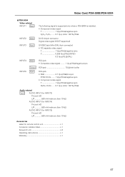
... Ω/negative sync. PB/CB, PR/CR ........ 0.7 Vp-p (color 100 %)/75 Ω Audio-related Input AUDIO INPUT (for INPUT3) Pin jack (×2) L/R 500 mVrms/more than 10 kΩ AUDIO INPUT (for INPUT4) Pin jack (×2) L/R 500 mVrms/more than 10 kΩ AUDIO INPUT (for INPUT5) Pin jack (×2) L/R 500 mVrms/more than 10 kΩ...
... Ω/negative sync. PB/CB, PR/CR ........ 0.7 Vp-p (color 100 %)/75 Ω Audio-related Input AUDIO INPUT (for INPUT3) Pin jack (×2) L/R 500 mVrms/more than 10 kΩ AUDIO INPUT (for INPUT4) Pin jack (×2) L/R 500 mVrms/more than 10 kΩ AUDIO INPUT (for INPUT5) Pin jack (×2) L/R 500 mVrms/more than 10 kΩ...
Technical Manual
Page 50
... the card. Device mounting surface Impedance selector switch S-VIDEO INPUT3 VIDEO INPUT4 INPUT 3/4 AUDIO 75 Ω 2.2 kΩ ANALOG RGB HD (H/V SYNC) INPUT5 AUDIO 3 After inserting the video card all the way into the slot, confirm that weight...panel. When installing the unit, if a screw or other object should be necessary to drop screws or other damage to clean the PCI bus. Objects dropped inside of the Plasma Display. Installation Illustration depicts PDA-5003 model 1 Remove the protective cover over the video card slot on the Pioneer Plasma Display PDP-607CMX...
... the card. Device mounting surface Impedance selector switch S-VIDEO INPUT3 VIDEO INPUT4 INPUT 3/4 AUDIO 75 Ω 2.2 kΩ ANALOG RGB HD (H/V SYNC) INPUT5 AUDIO 3 After inserting the video card all the way into the slot, confirm that weight...panel. When installing the unit, if a screw or other object should be necessary to drop screws or other damage to clean the PCI bus. Objects dropped inside of the Plasma Display. Installation Illustration depicts PDA-5003 model 1 Remove the protective cover over the video card slot on the Pioneer Plasma Display PDP-607CMX...

Technical Manual
Page 51
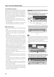
...insert and remove it frequently). 1 Remove the two screws holding the video card. S-VIDEO INPUT3 VIDEO INPUT4 INPUT 3/4 AUDIO ANALOG RGB HD (H/V SYNC) INPUT5 AUDIO 2 Holding the inside tabs, pull the video card straight out. Video Card Removal (Be careful not to gently ...mounting surface S-VIDEO INPUT3 VIDEO INPUT4 INPUT 3/4 AUDIO Impedance selector switch 75 Ω ANALOG RGB HD (H/V SYNC) 2.2 kΩ INPUT5 AUDIO Video Card: PDA-5003/PDA-5004 51 4 Affix the accessory connector indicator label to the Plasma Display then affix the remote control label to ...
...insert and remove it frequently). 1 Remove the two screws holding the video card. S-VIDEO INPUT3 VIDEO INPUT4 INPUT 3/4 AUDIO ANALOG RGB HD (H/V SYNC) INPUT5 AUDIO 2 Holding the inside tabs, pull the video card straight out. Video Card Removal (Be careful not to gently ...mounting surface S-VIDEO INPUT3 VIDEO INPUT4 INPUT 3/4 AUDIO Impedance selector switch 75 Ω ANALOG RGB HD (H/V SYNC) 2.2 kΩ INPUT5 AUDIO Video Card: PDA-5003/PDA-5004 51 4 Affix the accessory connector indicator label to the Plasma Display then affix the remote control label to ...
Technical Manual
Page 60
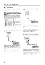
...) stereo mini jack (L/R) and the SPEAKER (L/R) terminals according to the video input selection. 60 Sound is installed, the Plasma Display provides four or five audio input jacks and one audio output jack. Video input INPUT1 INPUT2 INPUT5 INPUT3 INPUT4 Audio input Sound output Stereo mini jack (L/R) Stereo mini jack (L/R) Pin jacks (L/R) Pin jacks (L/R) *1 Pin jacks...
...) stereo mini jack (L/R) and the SPEAKER (L/R) terminals according to the video input selection. 60 Sound is installed, the Plasma Display provides four or five audio input jacks and one audio output jack. Video input INPUT1 INPUT2 INPUT5 INPUT3 INPUT4 Audio input Sound output Stereo mini jack (L/R) Stereo mini jack (L/R) Pin jacks (L/R) Pin jacks (L/R) *1 Pin jacks...
Technical Manual
Page 61
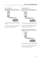
... the video input selection. Video Card: PDA-5003/PDA-5004 [When using PDA-5003] Audio connection for component connected to INPUT3 or INPUT4 INPUT 3/4 AUDIO R L [When using PDA-5004] Audio connection for component connected to INPUT3 INPUT3 AUDIO R L Audio input to the AUDIO R/L (INPUT3/4) pin jacks is possible for a component connected to the video input selection...
... the video input selection. Video Card: PDA-5003/PDA-5004 [When using PDA-5003] Audio connection for component connected to INPUT3 or INPUT4 INPUT 3/4 AUDIO R L [When using PDA-5004] Audio connection for component connected to INPUT3 INPUT3 AUDIO R L Audio input to the AUDIO R/L (INPUT3/4) pin jacks is possible for a component connected to the video input selection...
Technical Manual
Page 150
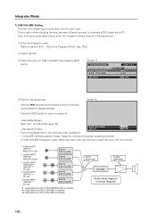
... PDA-5003/PDA-5004 is installed. #1: Applicable only when a PDA-5003 is installed. #2: Applicable only when a PDA-5004 is installed. After muting the audio before hand, enter the integrator mode and perform the adjustment. 1 Enter the integrator mode. (Refer to match the input with high volume to section 5.4.1, ..."About the Integrator Mode" (pg. 142).) 2 Select 'SETUP'. 3 Place the cursor on the remote control or the maincontrol panel to 20 (initial value: 20) SUB VOLUME SET SET : 20 MENU EXIT Performing adjustment in the following order is effective. 1.
... PDA-5003/PDA-5004 is installed. #1: Applicable only when a PDA-5003 is installed. #2: Applicable only when a PDA-5004 is installed. After muting the audio before hand, enter the integrator mode and perform the adjustment. 1 Enter the integrator mode. (Refer to match the input with high volume to section 5.4.1, ..."About the Integrator Mode" (pg. 142).) 2 Select 'SETUP'. 3 Place the cursor on the remote control or the maincontrol panel to 20 (initial value: 20) SUB VOLUME SET SET : 20 MENU EXIT Performing adjustment in the following order is effective. 1.

Technical Manual
Page 194
...screen to 14:9. SZMS00 + + Sets SCREEN SIZE to OFF. VIDEO MTN PMTS00 + Turns video mute to DOT BY DOT. AUDIO VOL + + Adjusts audio volume. MSSS03 + Sets the PinP subscreen size to PinP (lower right). MSTS01 + + Sets the MULTI SCREEN to 2 ... Command 425CMX = Command 42MXE10 / Command 607CMX = Command 60MXE20) 7 Normal Operation Related Commands Command 434CMX 505CMX Command 425CMX Command 607CMX Function POWER POF + + Turns the power OFF. INPS03 + + Switches the main screen to 4. AMN AMTS00 + Turns audio mute to INPUT2. INPS02 + + Switches...
...screen to 14:9. SZMS00 + + Sets SCREEN SIZE to OFF. VIDEO MTN PMTS00 + Turns video mute to DOT BY DOT. AUDIO VOL + + Adjusts audio volume. MSSS03 + Sets the PinP subscreen size to PinP (lower right). MSTS01 + + Sets the MULTI SCREEN to 2 ... Command 425CMX = Command 42MXE10 / Command 607CMX = Command 60MXE20) 7 Normal Operation Related Commands Command 434CMX 505CMX Command 425CMX Command 607CMX Function POWER POF + + Turns the power OFF. INPS03 + + Switches the main screen to 4. AMN AMTS00 + Turns audio mute to INPUT2. INPS02 + + Switches...
Technical Manual
Page 200
... from the adjustment value. Obtains integrator/PICTURE information. Obtains integrator/WHITE BALANCE information. Obtains Menu Integrator/OPTION information. Obtains audio status. RMCS11 Remote control key: CURSOR LEFT - - RMCS25 Remote control key: MENU 200 Number direct Last Effective Minimum...- OTHER - - IM3 + INFORMATION write-in (4-6 characters). - RS-232C Adjustment Command 434CMX 505CMX Command 425CMX Command 607CMX Function - Number direct Last Effective Minimum Maximum memory Comment New New New New New New New New New New 7 ...
... from the adjustment value. Obtains integrator/PICTURE information. Obtains integrator/WHITE BALANCE information. Obtains Menu Integrator/OPTION information. Obtains audio status. RMCS11 Remote control key: CURSOR LEFT - - RMCS25 Remote control key: MENU 200 Number direct Last Effective Minimum...- OTHER - - IM3 + INFORMATION write-in (4-6 characters). - RS-232C Adjustment Command 434CMX 505CMX Command 425CMX Command 607CMX Function - Number direct Last Effective Minimum Maximum memory Comment New New New New New New New New New New 7 ...
Technical Manual
Page 202
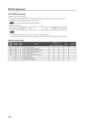
...Obtains time information. - Number direct Last Effective Minimum Maximum memory Comment 202 GSO QSO + Obtains Menu Integrator/OPTION information. - QAP + Obtains audio status. - QSU + Obtains various machine names. RS-232C Adjustment 5.5.6 QUEST Commands What are given inside brackets < >. • Data ...is output in the ID when sending the command. 7 Quest Command Table Command 434CMX 505CMX Command 425CMX Command 607CMX Function GST QST + Obtains status information. Note Command names are QUEST commands? • Quest commands output TXD such ...
...Obtains time information. - Number direct Last Effective Minimum Maximum memory Comment 202 GSO QSO + Obtains Menu Integrator/OPTION information. - QAP + Obtains audio status. - QSU + Obtains various machine names. RS-232C Adjustment 5.5.6 QUEST Commands What are given inside brackets < >. • Data ...is output in the ID when sending the command. 7 Quest Command Table Command 434CMX 505CMX Command 425CMX Command 607CMX Function GST QST + Obtains status information. Note Command names are QUEST commands? • Quest commands output TXD such ...

Technical Manual
Page 207
... Sequence Data Content 1 STX 2 Command echo-back 3 Main volume 4 Audio mute status 5 INPUT1 sub volume 6 INPUT2 sub volume 7 INPUT3 sub volume 8 INPUT4 sub volume 9 INPUT5 sub volume 10 Check sum 11 ETX Size 1 Byte 3 Byte 3 ... Content 1 STX 2 Command echo-back 3 Machine name information 4 Check sum 5 ETX Size 1 Byte 3 Byte 18 Byte 2 Byte 1 Byte Remarks 02hex QAP (fixed) A (North America model): PDP-607CMX******** G (Europe-general model): PDP-60MXE20******* 03hex 207
... Sequence Data Content 1 STX 2 Command echo-back 3 Main volume 4 Audio mute status 5 INPUT1 sub volume 6 INPUT2 sub volume 7 INPUT3 sub volume 8 INPUT4 sub volume 9 INPUT5 sub volume 10 Check sum 11 ETX Size 1 Byte 3 Byte 3 ... Content 1 STX 2 Command echo-back 3 Machine name information 4 Check sum 5 ETX Size 1 Byte 3 Byte 18 Byte 2 Byte 1 Byte Remarks 02hex QAP (fixed) A (North America model): PDP-607CMX******** G (Europe-general model): PDP-60MXE20******* 03hex 207

Technical Manual
Page 208
...to "DRE MID". Displays present setting of SIDE MASK to overlay 1. Displays present color off . Resets still picture movement function. Selects audio output fix. Sets gradation to "DRE LOW". Permits loudness MCN MCY MGFS01 MSCS01 SIM SIMS01 SIMS02 SIMS03 SZMS04 SZMS08 MIR PLN PLY PUCS02 ...setting of SIDE MASK. Sets gradation to MODE2. Turns on MULTI SCREEN. Turns on VIDEO WALL. Selects audio output variable. 7 Table of commands not compatible with PDP-434CMX to PDP-425CMX AJN AJY COF COFS00 COFS01 DPR FXO FRCS02 FRCS03 GRAS04 GRAS05 GRAS06 GRAS07 LNN LNY Ends 232C ...
...to "DRE MID". Displays present setting of SIDE MASK to overlay 1. Displays present color off . Resets still picture movement function. Selects audio output fix. Sets gradation to "DRE LOW". Permits loudness MCN MCY MGFS01 MSCS01 SIM SIMS01 SIMS02 SIMS03 SZMS04 SZMS08 MIR PLN PLY PUCS02 ...setting of SIDE MASK. Sets gradation to MODE2. Turns on MULTI SCREEN. Turns on VIDEO WALL. Selects audio output variable. 7 Table of commands not compatible with PDP-434CMX to PDP-425CMX AJN AJY COF COFS00 COFS01 DPR FXO FRCS02 FRCS03 GRAS04 GRAS05 GRAS06 GRAS07 LNN LNY Ends 232C ...
Technical Manual
Page 212
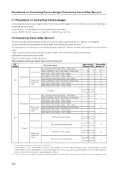
... 60 50 60 50 60 60 75 85 50 60 50 60 50 60 50 60 50 60 72 60 75 85 50 60 72 60 75 85 Frame delay number (V) 4 3 2 1 4 4 2 2 2 3 1 4 2 1 2 2 2 *1: The FRC object signal in the PC signal is as images from a surveillance camera, could damage or reduce the life of the panel. It is the guideline when considering the audio delay time...
... 60 50 60 50 60 60 75 85 50 60 50 60 50 60 50 60 50 60 72 60 75 85 50 60 72 60 75 85 Frame delay number (V) 4 3 2 1 4 4 2 2 2 3 1 4 2 1 2 2 2 *1: The FRC object signal in the PC signal is as images from a surveillance camera, could damage or reduce the life of the panel. It is the guideline when considering the audio delay time...


