Operating Instructions
Page 6
... with Video Card Model Number: PDP-507CMX/PDP-607CMX (Plasma Display) PDA-5003/PDA-5004 (Video Card) Product Category: Class B Personal Computers & Peripherals Responsible Party Name: PIONEER ELECTRONICS SERVICE, INC. Phone Number: 800-421-1625 For Business Customer URL: http://www.pioneerelectronics.com Should this product require service in Canada, please contact a Pioneer Canadian Authorized Dealer to the following address: Pioneer Electronics of the FCC Rules. Customer Support...
... with Video Card Model Number: PDP-507CMX/PDP-607CMX (Plasma Display) PDA-5003/PDA-5004 (Video Card) Product Category: Class B Personal Computers & Peripherals Responsible Party Name: PIONEER ELECTRONICS SERVICE, INC. Phone Number: 800-421-1625 For Business Customer URL: http://www.pioneerelectronics.com Should this product require service in Canada, please contact a Pioneer Canadian Authorized Dealer to the following address: Pioneer Electronics of the FCC Rules. Customer Support...
Operating Instructions
Page 7
... 3 How to use this manual 3 Checking supplied accessories 5 Part Names and Functions 6 Main unit 6 Remote control unit 7 Connection panel (PDP-507CMX 9 Connection panel (PDP-607CMX 10 Installation and Connections 11 Installation of the unit 11 Connection to a personal computer 13 Audio connections 14 Power cord connection 15 How to route cables 16 System Settings 17 Setting the onscreen display language 17 Settings after connections 18 Operation 19 Selecting input source 19 Adjusting sound volume 20 Muting the sound 20 Confirming current status 20 Changing screen size 21...
... 3 How to use this manual 3 Checking supplied accessories 5 Part Names and Functions 6 Main unit 6 Remote control unit 7 Connection panel (PDP-507CMX 9 Connection panel (PDP-607CMX 10 Installation and Connections 11 Installation of the unit 11 Connection to a personal computer 13 Audio connections 14 Power cord connection 15 How to route cables 16 System Settings 17 Setting the onscreen display language 17 Settings after connections 18 Operation 19 Selecting input source 19 Adjusting sound volume 20 Muting the sound 20 Confirming current status 20 Changing screen size 21...
Operating Instructions
Page 8
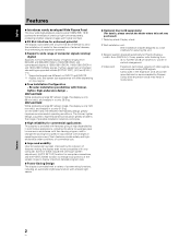
....) 1 Table top stand: Display stand. 2 Wall installation unit: Wall installation bracket designed as a wall interface for securing the unit. 3 Speaker system designed specifically for Plasma Displays (width: 9 cm (3-9/16 in.)): 2-way speaker units featuring 5 cm (2 in.) tweeter and 8 cm (3-3/16 in.) woofer in vertical arrangement. 4 Video card: Expansion card allows viewing of video signals and computer analog RGB signals. Such features provide safety and highendurance under conditions of commercial use. ¶ Improved usability User convenience...
....) 1 Table top stand: Display stand. 2 Wall installation unit: Wall installation bracket designed as a wall interface for securing the unit. 3 Speaker system designed specifically for Plasma Displays (width: 9 cm (3-9/16 in.)): 2-way speaker units featuring 5 cm (2 in.) tweeter and 8 cm (3-3/16 in.) woofer in vertical arrangement. 4 Video card: Expansion card allows viewing of video signals and computer analog RGB signals. Such features provide safety and highendurance under conditions of commercial use. ¶ Improved usability User convenience...
Operating Instructions
Page 12
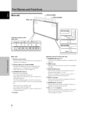
... indicator flashes green once every one second when the [POWER MGT.] function is in operation or standby mode (page 19). 6 MENU button Press to open and close the on the main unit STANDBY/ON 5 DISPLAY MENU / SET 67 INPUT SCREEN SIZE - When not indicated by onscreen menus, used for adjusting the sound volume (pages 19 and 20). Part Names and Functions 6 En VOL + 89 0 PDP-507CMX 1 STANDBY ON 23 PDP-607CMX 31 Main unit 1 Remote control...
... indicator flashes green once every one second when the [POWER MGT.] function is in operation or standby mode (page 19). 6 MENU button Press to open and close the on the main unit STANDBY/ON 5 DISPLAY MENU / SET 67 INPUT SCREEN SIZE - When not indicated by onscreen menus, used for adjusting the sound volume (pages 19 and 20). Part Names and Functions 6 En VOL + 89 0 PDP-507CMX 1 STANDBY ON 23 PDP-607CMX 31 Main unit 1 Remote control...
Operating Instructions
Page 13
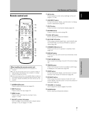
... switch between main screen and subscreen (page 23). # PIP SHIFT button When using computer signal input, automatically sets the [POSITION], [CLOCK] and [PHASE] to wear out, the operable distance will gradually become shorter. SET button Button used by professional installers. 0 AUTO SET UP button When using the picture-in operation or standby mode (page 19). = DISPLAY button Press to view the unit's current input and setup mode (page 20). ~ POINT ZOOM button Use to select and enlarge one part...
... switch between main screen and subscreen (page 23). # PIP SHIFT button When using computer signal input, automatically sets the [POSITION], [CLOCK] and [PHASE] to wear out, the operable distance will gradually become shorter. SET button Button used by professional installers. 0 AUTO SET UP button When using the picture-in operation or standby mode (page 19). = DISPLAY button Press to view the unit's current input and setup mode (page 20). ~ POINT ZOOM button Use to select and enlarge one part...
Operating Instructions
Page 15
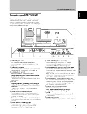
... does not support the display of an external left speaker. This connector is selected. Note: The video signal will not be output from the AUDIO (OUTPUT) jack when the MAIN POWER switch is set to OFF or ON (standby) (page 14). 6 AUDIO (INPUT1) (Stereo mini jack) Use to obtain sound when INPUT1 is used for Plasma Display setup adjustments. 5 AUDIO (OUTPUT) (Stereo mini jack) Use to these connectors without first consulting your Pioneer installation technician. Connect a speaker that...
... does not support the display of an external left speaker. This connector is selected. Note: The video signal will not be output from the AUDIO (OUTPUT) jack when the MAIN POWER switch is set to OFF or ON (standby) (page 14). 6 AUDIO (INPUT1) (Stereo mini jack) Use to obtain sound when INPUT1 is used for Plasma Display setup adjustments. 5 AUDIO (OUTPUT) (Stereo mini jack) Use to these connectors without first consulting your Pioneer installation technician. Connect a speaker that...
Operating Instructions
Page 16
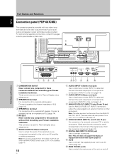
Note: This unit does not support the display of this connector without first consulting your Pioneer installation technician. Audio input/ output and speaker output terminals are used for Plasma Display setup adjustments. 2 SPEAKER (R) terminal For connection of 6 Ω (page 14). 4 RS-232C Never connect any component to an AV amplifier or similar component. For instructions regarding connections, consult the pages noted in standby mode.(page 13) 9 ANALOG RGB IN (INPUT1) (mini D-sub...
Note: This unit does not support the display of this connector without first consulting your Pioneer installation technician. Audio input/ output and speaker output terminals are used for Plasma Display setup adjustments. 2 SPEAKER (R) terminal For connection of 6 Ω (page 14). 4 RS-232C Never connect any component to an AV amplifier or similar component. For instructions regarding connections, consult the pages noted in standby mode.(page 13) 9 ANALOG RGB IN (INPUT1) (mini D-sub...
Operating Instructions
Page 19
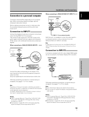
... with DVI output (digital RGB signal) can be sure to the Plasma Display's DVI connector. Note Depending on both units. NOTICE ¶ INPUT2 supports Microsoft "Plug & Play" (VESA DDC 2B) components. provided with combined horizontal and vertical sync signals). Secure by tightening the terminal screws on the type of computer model being connected, a conversion connector or adapter etc. See pages 17 to 44) for information regarding signals and display formats supported by...
... with DVI output (digital RGB signal) can be sure to the Plasma Display's DVI connector. Note Depending on both units. NOTICE ¶ INPUT2 supports Microsoft "Plug & Play" (VESA DDC 2B) components. provided with combined horizontal and vertical sync signals). Secure by tightening the terminal screws on the type of computer model being connected, a conversion connector or adapter etc. See pages 17 to 44) for information regarding signals and display formats supported by...
Operating Instructions
Page 24
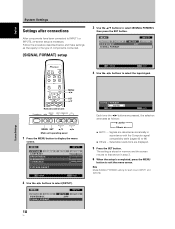
... SET button. System Settings MENU 2/3 SET 5/∞ Remote control unit STANDBY/ON DISPLAY MENU / SET INPUT SCREEN SIZE - VOL + MENU SET 5/∞ 2/3 Main unit operating panel 1 Press the MENU button to select [SETUP]. SIGNAL FORMAT INPUT1 SETUP OPTION :OFF 18 En SIGNAL FORMAT : AUTO SET SET MENU EXIT Each time the 2/3 buttons are pressed, the selection alternates as they apply to the type of components connected. [SIGNAL FORMAT] setup 3 Use the 5/∞ buttons to select [SIGNAL FORMAT], then press the SET button. The setting is stored in memory and the screen...
... SET button. System Settings MENU 2/3 SET 5/∞ Remote control unit STANDBY/ON DISPLAY MENU / SET INPUT SCREEN SIZE - VOL + MENU SET 5/∞ 2/3 Main unit operating panel 1 Press the MENU button to select [SETUP]. SIGNAL FORMAT INPUT1 SETUP OPTION :OFF 18 En SIGNAL FORMAT : AUTO SET SET MENU EXIT Each time the 2/3 buttons are pressed, the selection alternates as they apply to the type of components connected. [SIGNAL FORMAT] setup 3 Use the 5/∞ buttons to select [SIGNAL FORMAT], then press the SET button. The setting is stored in memory and the screen...
Operating Instructions
Page 25
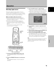
... cause a phenomenon known as "screen burn" which leaves a ghost, or residual, image of the picture on the screen. STANDBY/ON INPUT VOL +/- Outlined on the following message will light red. 2 Press the STANDBY/ON button to adjust the sound volume. STANDBY/ ON INPUT VOLUME [+/-] Remote control unit STANDBY/ON DISPLAY MENU / SET INPUT SCREEN SIZE - POL.H: - Operation 19 En Doing so may continue to light for a long time. Main unit operating panel 1 Set the rear panel MAIN POWER switch to INPUT1 and INPUT2 as...
... cause a phenomenon known as "screen burn" which leaves a ghost, or residual, image of the picture on the screen. STANDBY/ON INPUT VOL +/- Outlined on the following message will light red. 2 Press the STANDBY/ON button to adjust the sound volume. STANDBY/ ON INPUT VOLUME [+/-] Remote control unit STANDBY/ON DISPLAY MENU / SET INPUT SCREEN SIZE - POL.H: - Operation 19 En Doing so may continue to light for a long time. Main unit operating panel 1 Set the rear panel MAIN POWER switch to INPUT1 and INPUT2 as...
Operating Instructions
Page 27
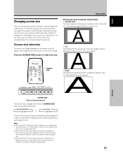
... manufacturer's intentions. For optimal viewing, we recommend that you select the screen mode that best matches the video source that when the display is turned on a wide screen, a portion of the picture may be set in order to the source. 2 4:3 The display fills the screen as much as follows. 3 DOT BY DOT or 4:3 2 3 FULL 4:3 2 Consult the Computer signal compatibility table (pages 42 to select the size. SCREEN SIZE Remote control unit STANDBY/ON DISPLAY MENU / SET INPUT SCREEN SIZE -
... manufacturer's intentions. For optimal viewing, we recommend that you select the screen mode that best matches the video source that when the display is turned on a wide screen, a portion of the picture may be set in order to the source. 2 4:3 The display fills the screen as much as follows. 3 DOT BY DOT or 4:3 2 3 FULL 4:3 2 Consult the Computer signal compatibility table (pages 42 to select the size. SCREEN SIZE Remote control unit STANDBY/ON DISPLAY MENU / SET INPUT SCREEN SIZE -
Operating Instructions
Page 30
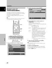
... Plasma Display automatically returns to normal operation from the [POWER MGT.] function's standby mode, either operate your computer, or press the INPUT button. To return to operating mode: To return to normal operating mode (*1). *1. E N H A N C E SETUP : : : : INPUT1 OPTION 0 0 0 0 PICTURE RESET SET ENTER MENU EXIT 2 Use the 2/3 buttons to confirm selection of [POWER MGT.]. Each time the button is pressed, the setting alternates as follows: 3 OFF ON 2 ÷ OFF ..... MENU PICTURE SCREEN CONTRAST BRIGHTNESS H.ENHANCE V. SIGNAL FORMAT...
... Plasma Display automatically returns to normal operation from the [POWER MGT.] function's standby mode, either operate your computer, or press the INPUT button. To return to operating mode: To return to normal operating mode (*1). *1. E N H A N C E SETUP : : : : INPUT1 OPTION 0 0 0 0 PICTURE RESET SET ENTER MENU EXIT 2 Use the 2/3 buttons to confirm selection of [POWER MGT.]. Each time the button is pressed, the setting alternates as follows: 3 OFF ON 2 ÷ OFF ..... MENU PICTURE SCREEN CONTRAST BRIGHTNESS H.ENHANCE V. SIGNAL FORMAT...
Operating Instructions
Page 32
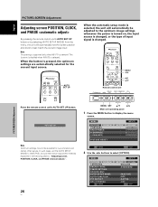
... will automatically set the [AUTO SETUP MODE] to [INACTIVE], and use the manual adjustment methods explained in the following section, "Adjusting screen POSITION, CLOCK, and PHASE ". 26 En MENU SET 5/∞ 2/3 Main unit operating panel 1 Press the MENU button to display the menu screen. VOL + PICTURE/SCREEN Adjustment Press the remote control unit's AUTO SET UP button. MENU PICTURE SCREEN CONTRAST BRIGHTNESS H.ENHANCE V. In such cases, set the screen position and clock to best match the current image input. Note This setting is supported only...
... will automatically set the [AUTO SETUP MODE] to [INACTIVE], and use the manual adjustment methods explained in the following section, "Adjusting screen POSITION, CLOCK, and PHASE ". 26 En MENU SET 5/∞ 2/3 Main unit operating panel 1 Press the MENU button to display the menu screen. VOL + PICTURE/SCREEN Adjustment Press the remote control unit's AUTO SET UP button. MENU PICTURE SCREEN CONTRAST BRIGHTNESS H.ENHANCE V. In such cases, set the screen position and clock to best match the current image input. Note This setting is supported only...
Operating Instructions
Page 37
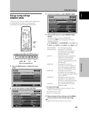
... menu screen. MENU PICTURE SCREEN LANGUAGE ENERGY SAVE TIMER SETTING S C R E E N M G T. The factory default setting is pressed, the setting changes as follows: 3 STANDARD1 3 STANDARD2 3 AUTO MUTE 2 MODE3 2 MODE2 2 MODE1 2 ÷ STANDARD1 .... Each time the SET button is [STANDARD]. VOL + MENU SET 5/∞ 2/3 Main unit operating panel 1 Press the MENU button to select [ENERGY SAVE]. MENU 2/3 SET 5/∞ Remote control unit STANDBY/ON DISPLAY MENU / SET INPUT SCREEN SIZE - MENU PICTURE SCREEN LANGUAGE ENERGY SAVE TIMER SETTING S C R E E N M G T. Effective at fixed...
... menu screen. MENU PICTURE SCREEN LANGUAGE ENERGY SAVE TIMER SETTING S C R E E N M G T. The factory default setting is pressed, the setting changes as follows: 3 STANDARD1 3 STANDARD2 3 AUTO MUTE 2 MODE3 2 MODE2 2 MODE1 2 ÷ STANDARD1 .... Each time the SET button is [STANDARD]. VOL + MENU SET 5/∞ 2/3 Main unit operating panel 1 Press the MENU button to select [ENERGY SAVE]. MENU 2/3 SET 5/∞ Remote control unit STANDBY/ON DISPLAY MENU / SET INPUT SCREEN SIZE - MENU PICTURE SCREEN LANGUAGE ENERGY SAVE TIMER SETTING S C R E E N M G T. Effective at fixed...
Operating Instructions
Page 38
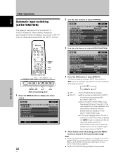
MENU 2/3 SET 5/∞ Remote control unit STANDBY/ON DISPLAY MENU / SET INPUT SCREEN SIZE - E N H A N C E PICTURE RESET SETUP : : : : INPUT1 OPTION 0 0 0 0 SET ENTER MENU EXIT 32 En 2 Use the 2/3 buttons to select [AUTO FUNCTION]. AUTO SETUP MODE AUTO FUNCTION PIP DETECT SPLIT FREEZE SET ENTER INPUT1 SETUP OPTION :ENGLISH : S TA N D A R D :INACTIVE :OFF :ACTIVE :OFF MENU EXIT 3 Use the 5/∞ buttons to select [OPTION]. MENU PICTURE SCREEN LANGUAGE ENERGY SAVE TIMER SETTING S C R E E N M G T. Each time the SET button is pressed, the selector function switches ...
MENU 2/3 SET 5/∞ Remote control unit STANDBY/ON DISPLAY MENU / SET INPUT SCREEN SIZE - E N H A N C E PICTURE RESET SETUP : : : : INPUT1 OPTION 0 0 0 0 SET ENTER MENU EXIT 32 En 2 Use the 2/3 buttons to select [AUTO FUNCTION]. AUTO SETUP MODE AUTO FUNCTION PIP DETECT SPLIT FREEZE SET ENTER INPUT1 SETUP OPTION :ENGLISH : S TA N D A R D :INACTIVE :OFF :ACTIVE :OFF MENU EXIT 3 Use the 5/∞ buttons to select [OPTION]. MENU PICTURE SCREEN LANGUAGE ENERGY SAVE TIMER SETTING S C R E E N M G T. Each time the SET button is pressed, the selector function switches ...

Operating Instructions
Page 40
... press the SET button to return to the normal screen image. [PROGRAM] setting ÷ Every day, power turns on at 10:00. MENU PICTURE SCREEN LANGUAGE ENERGY SAVE TIMER SETTING S C R E E N M G T. MENU PICTURE SCREEN CONTRAST BRIGHTNESS H.ENHANCE V. AUTO SETUP MODE AUTO FUNCTION PIP DETECT SPLIT FREEZE SET ENTER INPUT1 SETUP OPTION :ENGLISH : S TA N D A R D :INACTIVE :OFF :ACTIVE :OFF MENU EXIT 4 Use the 5/∞ buttons to operate a preset program. The factory default setting is pressed, the setting alternates as those set the last time the unit...
... press the SET button to return to the normal screen image. [PROGRAM] setting ÷ Every day, power turns on at 10:00. MENU PICTURE SCREEN LANGUAGE ENERGY SAVE TIMER SETTING S C R E E N M G T. MENU PICTURE SCREEN CONTRAST BRIGHTNESS H.ENHANCE V. AUTO SETUP MODE AUTO FUNCTION PIP DETECT SPLIT FREEZE SET ENTER INPUT1 SETUP OPTION :ENGLISH : S TA N D A R D :INACTIVE :OFF :ACTIVE :OFF MENU EXIT 4 Use the 5/∞ buttons to operate a preset program. The factory default setting is pressed, the setting alternates as those set the last time the unit...
Operating Instructions
Page 41
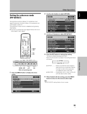
...no video signal or sync signal. VOL + MENU SET 5/∞ 2/3 Main unit operating panel 1 Press the MENU button to select [OPTION]. MENU PICTURE SCREEN CONTRAST BRIGHTNESS H.ENHANCE V. MENU PICTURE SCREEN LANGUAGE ENERGY SAVE TIMER SETTING S C R E E N M G T. The factory default setting is [ACTIVE]. Subscreens with the setting, press the MENU button to return to the normal screen image. E N H A N C E SETUP : : : : INPUT1 OPTION 0 0 0 0 PICTURE RESET SET ENTER MENU EXIT Other Operations 2 Use the 2/3 buttons to display the menu screen. Note The [PIP DETECT] setting...
...no video signal or sync signal. VOL + MENU SET 5/∞ 2/3 Main unit operating panel 1 Press the MENU button to select [OPTION]. MENU PICTURE SCREEN CONTRAST BRIGHTNESS H.ENHANCE V. MENU PICTURE SCREEN LANGUAGE ENERGY SAVE TIMER SETTING S C R E E N M G T. The factory default setting is [ACTIVE]. Subscreens with the setting, press the MENU button to return to the normal screen image. E N H A N C E SETUP : : : : INPUT1 OPTION 0 0 0 0 PICTURE RESET SET ENTER MENU EXIT Other Operations 2 Use the 2/3 buttons to display the menu screen. Note The [PIP DETECT] setting...

Operating Instructions
Page 45
... connection? (pages 17 to 18) • Is the correct input selected? (page 19) • Is a non-compatible signal being input? (pages 42 to 44) • Is the [PICTURE] setting correct? (page 25) Problems commonly mistaken as picture size made correctly? (pages 21 to 22 and 27 to another screen size (page 21). • Are [SCREEN] mode adjustments such as breakdown Problem • The screen is displayed in sound being used...
... connection? (pages 17 to 18) • Is the correct input selected? (page 19) • Is a non-compatible signal being input? (pages 42 to 44) • Is the [PICTURE] setting correct? (page 25) Problems commonly mistaken as picture size made correctly? (pages 21 to 22 and 27 to another screen size (page 21). • Are [SCREEN] mode adjustments such as breakdown Problem • The screen is displayed in sound being used...
Operating Instructions
Page 46
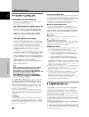
... of time. If the green light displays a flashing pattern other applications where a fixed image will change speed automatically in accordance with ambient temperature conditions (the fan sound will be employed when using the Plasma Display as a surveillance monitor or in compliance with a cooling fan designed to a location where its speed). If the problem persists, disconnect the power plug and consult your dealer or a service center. If the same image is displayed...
... of time. If the green light displays a flashing pattern other applications where a fixed image will change speed automatically in accordance with ambient temperature conditions (the fan sound will be employed when using the Plasma Display as a surveillance monitor or in compliance with a cooling fan designed to a location where its speed). If the problem persists, disconnect the power plug and consult your dealer or a service center. If the same image is displayed...
Operating Instructions
Page 47
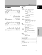
... buffer INPUT2 Input DVI-D 24-pin connector Digital RGB signal (DVI compliant TMDS signal) *Compatible with Microsoft "Plug & Play" (VESA DDC 2B) Audio Input AUDIO INPUT (for INPUT1) Stereo mini jack L/R ... 500 mVrms/more than 10 kΩ Output AUDIO INPUT (for audio cables 3 Operating Instructions 1 Warranty 1 ÷ Due to improvements, specifications and design are subject to 40 °C Additional Information Input/output Video INPUT1 Input Mini D-sub 15 pin (socket connector) RGB signal (G ON SYNC compatible) RGB ... 0.7 Vp...
... buffer INPUT2 Input DVI-D 24-pin connector Digital RGB signal (DVI compliant TMDS signal) *Compatible with Microsoft "Plug & Play" (VESA DDC 2B) Audio Input AUDIO INPUT (for INPUT1) Stereo mini jack L/R ... 500 mVrms/more than 10 kΩ Output AUDIO INPUT (for audio cables 3 Operating Instructions 1 Warranty 1 ÷ Due to improvements, specifications and design are subject to 40 °C Additional Information Input/output Video INPUT1 Input Mini D-sub 15 pin (socket connector) RGB signal (G ON SYNC compatible) RGB ... 0.7 Vp...


