User Guide
Page 8
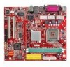
...DMA 33/66/100/133 operation modes. • Can connect up to 3.2GHz, and Intel P4 Prescott Celeron CPU. (For the latest information about CPU, please visit http://www.msi.com.tw/program/products/mainboard/mbd/pro_mbd_cpu_support.php ) Chipset • VIA® P4M800CE chipset - DDR SDRAM ...) processor. • FSB @ 800/533MHz. • Supports Intel P4 Prescott CPU up to 2GB PC3200 (DDR400) SDRAMs. • Supports 2.5v DDR SDRAM. (For the updated supporting memory modules, please visit http://www.msi.com.tw/program/products/mainboard/mbd/pro_mbd_trp_list.php ) Slots • One AGP ...
...DMA 33/66/100/133 operation modes. • Can connect up to 3.2GHz, and Intel P4 Prescott Celeron CPU. (For the latest information about CPU, please visit http://www.msi.com.tw/program/products/mainboard/mbd/pro_mbd_cpu_support.php ) Chipset • VIA® P4M800CE chipset - DDR SDRAM ...) processor. • FSB @ 800/533MHz. • Supports Intel P4 Prescott CPU up to 2GB PC3200 (DDR400) SDRAMs. • Supports 2.5v DDR SDRAM. (For the updated supporting memory modules, please visit http://www.msi.com.tw/program/products/mainboard/mbd/pro_mbd_trp_list.php ) Slots • One AGP ...
User Guide
Page 10
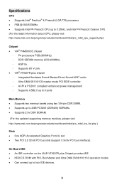
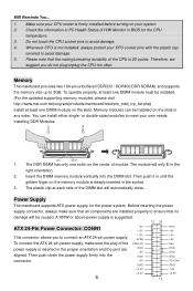
...533 MHz 800 MHz DDR 333 OK OK DDR 400 OK OK 4 It also provides the instructions on the mainboard. MSI Reminds You... Central Processing Unit: CPU The mainboard supports Intel® Pentium 4 processor. When you do not guarantee the damages or risks caused by inadequate... is designed to prevent overheating. We do not have the CPU cooler, contact your components are installing the CPU, make sure to install the cooler to support overclocking. For the latest information about CPU, please visit http://www.msi.com.tw/program/products/mainboard/mbd/pro_mbd_cpu_support.php.
...533 MHz 800 MHz DDR 333 OK OK DDR 400 OK OK 4 It also provides the instructions on the mainboard. MSI Reminds You... Central Processing Unit: CPU The mainboard supports Intel® Pentium 4 processor. When you do not guarantee the damages or risks caused by inadequate... is designed to prevent overheating. We do not have the CPU cooler, contact your components are installing the CPU, make sure to install the cooler to support overclocking. For the latest information about CPU, please visit http://www.msi.com.tw/program/products/mainboard/mbd/pro_mbd_cpu_support.php.
User Guide
Page 11
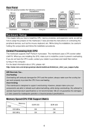
... of it to lock the hooks. 15. Remove the cap from damage. Use your index finger to allow the whole module to lift up the CPU. 5 Then cover the load plate onto the package. 12. Press the four hooks down the cooler until its four clips get wedged into the socket... on the computer. Push down to apply some silicon heat transfer compound on it to the hook of CPU Clip with 2 fingers. Rotate it to install the CPU & cooler correctly. The CPU has a plastic cap on CPU before turning on the mainboard with the hook under retention tab. 13. Lift the load lever up...
... of it to lock the hooks. 15. Remove the cap from damage. Use your index finger to allow the whole module to lift up the CPU. 5 Then cover the load plate onto the package. 12. Press the four hooks down the cooler until its four clips get wedged into the socket... on the computer. Push down to apply some silicon heat transfer compound on it to the hook of CPU Clip with 2 fingers. Rotate it to install the CPU & cooler correctly. The CPU has a plastic cap on CPU before turning on the mainboard with the hook under retention tab. 13. Lift the load lever up...
User Guide
Page 12
Whenever CPU is deeply inserted in the proper orientation and the pins are installed properly to connect an ATX 24-pin power supply. To operate properly, at least one DIMM module must be installed. (For the updated supporting memory modules, please visit http://www.msi.com.tw/program/products/...mainboard/mbd/pro_mbd_trp_list.php) Install at each side of module. or double-sided modules to meet your CPU...
Whenever CPU is deeply inserted in the proper orientation and the pins are installed properly to connect an ATX 24-pin power supply. To operate properly, at least one DIMM module must be installed. (For the updated supporting memory modules, please visit http://www.msi.com.tw/program/products/...mainboard/mbd/pro_mbd_trp_list.php) Install at each side of module. or double-sided modules to meet your CPU...
User Guide
Page 13
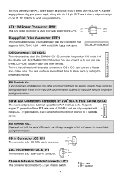
...provide power to Slave mode by setting its jumper. You may use the 20-pin ATX power supply as you 'd like . You must configure the second drive to 1 hard disk device. MSI Reminds You... MSI Reminds You... There is for jumper setting instructions. IDE1 can connect to Slave mode...Slave drive. GND L AUX In Connector: AUX_IN1 L The connector is also a foolproof design on one cable, you must configure second hard drive to the CPU. 12V Floppy Disk Drive Connector: FDD1 The mainboard provides a standard floppy disk drive connector that supports 360K, 720K, 1.2M, 1.44M and 2.88M floppy...
...provide power to Slave mode by setting its jumper. You may use the 20-pin ATX power supply as you 'd like . You must configure the second drive to 1 hard disk device. MSI Reminds You... MSI Reminds You... There is for jumper setting instructions. IDE1 can connect to Slave mode...Slave drive. GND L AUX In Connector: AUX_IN1 L The connector is also a foolproof design on one cable, you must configure second hard drive to the CPU. 12V Floppy Disk Drive Connector: FDD1 The mainboard provides a standard floppy disk drive connector that supports 360K, 720K, 1.2M, 1.44M and 2.88M floppy...
User Guide
Page 14
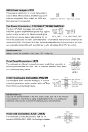
... to the front panel switches and LEDs. VCC(1) VCC(2) GND USB1USB1+ AUD_RET_L Key AUD_RET_R AUD_VCC AUD_GND 10 9 21 AUD_FPOUT_L HP_ON AUD_FPOUT_R AUD_MIC_BIAS AUD_MIC MSI Reminds You... 10 9 If you must use a specially designed fan with Intel® Front Panel I /O Connectivity Design Guide. When connecting the...USB0- JFP2 is compliant with +12V. BIOS Flash Jumper: JWP1 This jumper is used to the connectors, always take advantage of the CPU fan control. MSI Reminds You... When locked, the BIOS boot block area cannot be updated. Otherwise, the Line-Out connector on -board, you do...
... to the front panel switches and LEDs. VCC(1) VCC(2) GND USB1USB1+ AUD_RET_L Key AUD_RET_R AUD_VCC AUD_GND 10 9 21 AUD_FPOUT_L HP_ON AUD_FPOUT_R AUD_MIC_BIAS AUD_MIC MSI Reminds You... 10 9 If you must use a specially designed fan with Intel® Front Panel I /O Connectivity Design Guide. When connecting the...USB0- JFP2 is compliant with +12V. BIOS Flash Jumper: JWP1 This jumper is used to the connectors, always take advantage of the CPU fan control. MSI Reminds You... When locked, the BIOS boot block area cannot be updated. Otherwise, the Line-Out connector on -board, you do...
User Guide
Page 17
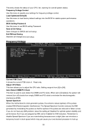
...even a slight jitter can introduce a temporary boost in clock speed which may just cause your CPU, fan, warning for overall system status. Save & Exit Setup Save changes to flatter curves. Adjust CPU Ratio This item allows you do not have any EMI problem, leave the setting at Disabled... the DIMM and PCI slots. When set BIOS setting Password. Spread Spectrum When the motherboard's clock generator pulses, the extreme values (spikes) of . Load Optimized Defaults Use this menu to adjust the CPU ratio. If you to load factory default settings into the BIOS for frequency/voltage control...
...even a slight jitter can introduce a temporary boost in clock speed which may just cause your CPU, fan, warning for overall system status. Save & Exit Setup Save changes to flatter curves. Adjust CPU Ratio This item allows you do not have any EMI problem, leave the setting at Disabled... the DIMM and PCI slots. When set BIOS setting Password. Spread Spectrum When the motherboard's clock generator pulses, the extreme values (spikes) of . Load Optimized Defaults Use this menu to adjust the CPU ratio. If you to load factory default settings into the BIOS for frequency/voltage control...
User Guide
Page 18
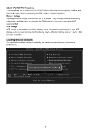
... Defaults You can increase the DDR speed. Setting options: 1.5V to a higher frequency. Any changes made to this setting may be affected. Adjust CPU/AGP/PCI Frequency This item allows you to increase the performance of your AGP display card when overclocking, but the stability may cause a stability issue...load the default values provided by the mainboard manufacturer for long-term purpose is adjustable in the field, allowing you to select the CPU/AGP/PCI Front Side Bus clock frequency (in MHz) and overclock the processor by adjusting the FSB clock to 1.85V at 0.05V increment.
... Defaults You can increase the DDR speed. Setting options: 1.5V to a higher frequency. Any changes made to this setting may be affected. Adjust CPU/AGP/PCI Frequency This item allows you to increase the performance of your AGP display card when overclocking, but the stability may cause a stability issue...load the default values provided by the mainboard manufacturer for long-term purpose is adjustable in the field, allowing you to select the CPU/AGP/PCI Front Side Bus clock frequency (in MHz) and overclock the processor by adjusting the FSB clock to 1.85V at 0.05V increment.
User Guide
Page 64
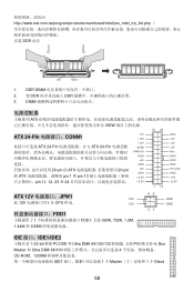
... PWR OK GND +5V GND +5V GND +3.3V +3.3V 1 13 GND +5V +5V +5V Res GND GND GND PS-ON# GND -12V +3.3V ATX 12V JPW1 12V 此 12V CPU 供电。 12V FDD1 1 FDD1,支持 360K, 720K, 1.2M, 1.44M 和 2.88M 42 31 GND GND IDE 接口...;式 0~4, Bus Master 和 Ultra DMA 66/100/133 4 CD-ROM、120MB IDE1 接口。IDE1 1 个 Master 1 个 Slave 58 http://www.msi.com.tw/program/products/mainboard/mbd/pro_mbd_trp_list.php DDR 内存 Volt Notch 1. DDR DIMM 2. 将 DDR DDR 3.
... PWR OK GND +5V GND +5V GND +3.3V +3.3V 1 13 GND +5V +5V +5V Res GND GND GND PS-ON# GND -12V +3.3V ATX 12V JPW1 12V 此 12V CPU 供电。 12V FDD1 1 FDD1,支持 360K, 720K, 1.2M, 1.44M 和 2.88M 42 31 GND GND IDE 接口...;式 0~4, Bus Master 和 Ultra DMA 66/100/133 4 CD-ROM、120MB IDE1 接口。IDE1 1 个 Master 1 个 Slave 58 http://www.msi.com.tw/program/products/mainboard/mbd/pro_mbd_trp_list.php DDR 内存 Volt Notch 1. DDR DIMM 2. 将 DDR DDR 3.
User Guide
Page 65
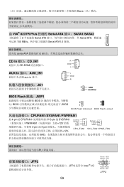
... 的 CPUFAN1 3-pin 的 SYSFAN1 PWRFAN1 12V 3-pin 或 4-pin 12V, Control Sensor +12V GND CPU_FAN1 Sensor +12V GND SY S _ FAN 1/ PWR _FAN GND CPU JFP2 JFP2 是符合 Intel ® I/O Reset HDD Switch LED 9 1 10 2 PowerPower Switch LED JFP2 59
... 的 CPUFAN1 3-pin 的 SYSFAN1 PWRFAN1 12V 3-pin 或 4-pin 12V, Control Sensor +12V GND CPU_FAN1 Sensor +12V GND SY S _ FAN 1/ PWR _FAN GND CPU JFP2 JFP2 是符合 Intel ® I/O Reset HDD Switch LED 9 1 10 2 PowerPower Switch LED JFP2 59
User Guide
Page 76
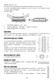
http://www.msi.com.tw/program/products/mainboard/mbd/pro_mbd_trp_list.php DDR 記憶體 Volt Notch 1. DIMM ATX 300W 12 24 ATX 24-Pin CONN1 ATX 24-Pin ATX 24-Pin 20-pin 的 ATX 20-pin 的 ATX pin 1 和 pin 13 pin 11, 12, 23 和 24 NC +12V +12V 5VSB PWR OK ...GND +5V GND +5V GND +3.3V +3.3V GND +5V +5V +5V Res GND GND GND PS-ON# GND -12V +3.3V 1 13 ATX 12V JPW1 12V 此 12V CPU 供電。 12V FDD1 1 FDD1,支援 360K, 720K, 1.2M, 1.44M 和 2.88M 42 31 GND GND IDE 介...
http://www.msi.com.tw/program/products/mainboard/mbd/pro_mbd_trp_list.php DDR 記憶體 Volt Notch 1. DIMM ATX 300W 12 24 ATX 24-Pin CONN1 ATX 24-Pin ATX 24-Pin 20-pin 的 ATX 20-pin 的 ATX pin 1 和 pin 13 pin 11, 12, 23 和 24 NC +12V +12V 5VSB PWR OK ...GND +5V GND +5V GND +3.3V +3.3V GND +5V +5V +5V Res GND GND GND PS-ON# GND -12V +3.3V 1 13 ATX 12V JPW1 12V 此 12V CPU 供電。 12V FDD1 1 FDD1,支援 360K, 720K, 1.2M, 1.44M 和 2.88M 42 31 GND GND IDE 介...
User Guide
Page 77
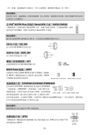
... 的 CPUFAN1 3-pin 的 SYSFAN1 PWRFAN1 12V 3-pin 或 4-pin 12V, Control Sensor +12V GND CPU_FAN1 Sensor +12V GND SY S _ FAN 1/ PWR _FAN GND CPU JFP2 JFP2 是符合 Intel ® I/O Reset HDD Switch LED 9 1 10 2 PowerPower Switch LED JFP2 71
... 的 CPUFAN1 3-pin 的 SYSFAN1 PWRFAN1 12V 3-pin 或 4-pin 12V, Control Sensor +12V GND CPU_FAN1 Sensor +12V GND SY S _ FAN 1/ PWR _FAN GND CPU JFP2 JFP2 是符合 Intel ® I/O Reset HDD Switch LED 9 1 10 2 PowerPower Switch LED JFP2 71
User Guide
Page 88
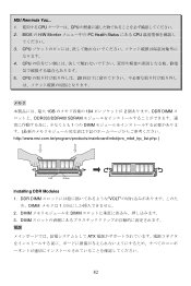
CPU 4. DIMM DIMM 3. BIOS の H/W Monitor PC Health Status にある CPU 3. DIMM ATX 82 CPU 5. DDR DIMM VOLT め、DIMM 1 2. MSI Reminds You... 1 CPU CPU 2. CPU 20 1GB 184 2 DDR DIMM DDR333/DDR400 SDRAM 1 つの DIMM http://www.msi.com.tw/program/products/mainboard/mbd/pro_mbd_trp_list.php ) Volt Notch Installing DDR Modules 1.
CPU 4. DIMM DIMM 3. BIOS の H/W Monitor PC Health Status にある CPU 3. DIMM ATX 82 CPU 5. DDR DIMM VOLT め、DIMM 1 2. MSI Reminds You... 1 CPU CPU 2. CPU 20 1GB 184 2 DDR DIMM DDR333/DDR400 SDRAM 1 つの DIMM http://www.msi.com.tw/program/products/mainboard/mbd/pro_mbd_trp_list.php ) Volt Notch Installing DDR Modules 1.

