User Guide
Page 9
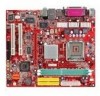
...Line-In/Line-Out/Mic) port - 1 RJ45 LAN jack - 1 VGA port - 1 COM2 pin header - 2 SATA 150 BIOS • The mainboard BIOS provides "Plug & Play" BIOS which detects the peripheral devices and expansion cards of the board automatically. • The mainboard provides a Desktop Management Interface (DMI) ...8226; On-Board Peripherals include: - 1 floppy port supports 2 FDDs with PCI 2.2. - Compliance with AC'97 v2.2 spec. Dimension • Micro-ATX Form Factor: 245mm x 210mm Mounting • 6 mounting holes. 3 Audio • AC97 link controller integrated in VT8237R plus. • Realtek...
...Line-In/Line-Out/Mic) port - 1 RJ45 LAN jack - 1 VGA port - 1 COM2 pin header - 2 SATA 150 BIOS • The mainboard BIOS provides "Plug & Play" BIOS which detects the peripheral devices and expansion cards of the board automatically. • The mainboard provides a Desktop Management Interface (DMI) ...8226; On-Board Peripherals include: - 1 floppy port supports 2 FDDs with PCI 2.2. - Compliance with AC'97 v2.2 spec. Dimension • Micro-ATX Form Factor: 245mm x 210mm Mounting • 6 mounting holes. 3 Audio • AC97 link controller integrated in VT8237R plus. • Realtek...
User Guide
Page 12
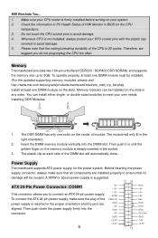
... installed. (For the updated supporting memory modules, please visit http://www.msi.com.tw/program/products/mainboard/mbd/pro_mbd_trp_list.php) Install at each side of the CPU is inserted in the right orientation. 2. To connect the ATX 24-pin power supply, make sure that the mating/unmating durability of ... is 20 cycles. Then push it in until the golden finger on the memory module is firmly installed before turning on the slots in BIOS for the power system. The plastic clip at least one notch on the slots. Before inserting the power supply connector, always make sure ...
... installed. (For the updated supporting memory modules, please visit http://www.msi.com.tw/program/products/mainboard/mbd/pro_mbd_trp_list.php) Install at each side of the CPU is inserted in the right orientation. 2. To connect the ATX 24-pin power supply, make sure that the mating/unmating durability of ... is 20 cycles. Then push it in until the golden finger on the memory module is firmly installed before turning on the slots in BIOS for the power system. The plastic clip at least one notch on the slots. Before inserting the power supply connector, always make sure ...
User Guide
Page 14
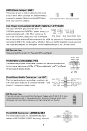
...mainboard provides a front panel connector for the proper CPU cooling fan. AUD_RET_L Key AUD_RET_R AUD_VCC AUD_GND 10 9 21 AUD_FPOUT_L HP_ON AUD_FPOUT_R AUD_MIC_BIAS AUD_MIC MSI Reminds You... 10 9 If you do not want to connect to the front audio header, pins 5 & 6, 9 & 10 have ...the rear audio ports. USB2.0 technology increases 8 (9)Key (10)USB0C USB0+ GND USB0- When locked, the BIOS boot block area cannot be updated. 2 2 1 1 BIOS Flash Unlocked BIOS Flash Locked Fan Power Connectors: CPUFAN1/SYSFAN1/PWRFAN1 The 4-pin CPUFAN1 (processor fan) and 3-pin SYSFAN1 (system ...
...mainboard provides a front panel connector for the proper CPU cooling fan. AUD_RET_L Key AUD_RET_R AUD_VCC AUD_GND 10 9 21 AUD_FPOUT_L HP_ON AUD_FPOUT_R AUD_MIC_BIAS AUD_MIC MSI Reminds You... 10 9 If you do not want to connect to the front audio header, pins 5 & 6, 9 & 10 have ...the rear audio ports. USB2.0 technology increases 8 (9)Key (10)USB0C USB0+ GND USB0- When locked, the BIOS boot block area cannot be updated. 2 2 1 1 BIOS Flash Unlocked BIOS Flash Locked Fan Power Connectors: CPUFAN1/SYSFAN1/PWRFAN1 The 4-pin CPUFAN1 (processor fan) and 3-pin SYSFAN1 (system ...
User Guide
Page 15
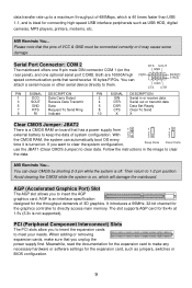
...you want to clear the system configuration, 1 2 3 Keep Data 1 2 3 Clear Data use the JBAT1 (Clear CMOS Jumper) to clear data. MSI Reminds You... PCI (Peripheral Component Interconnect) Slots The PCI slots allow you to insert the AGP graphics card. RTS SOUT GND [9]RI SIN[2] DSR CTS... (on , which is 40 times faster than USB 1.1, and is ideal for connecting high-speed USB interface peripherals such as jumpers, switches or BIOS configuration. 9 Meanwhile, read the documentation for the expansion card to make sure that the pins of VCC & GND must be connected correctly or ...
...you want to clear the system configuration, 1 2 3 Keep Data 1 2 3 Clear Data use the JBAT1 (Clear CMOS Jumper) to clear data. MSI Reminds You... PCI (Peripheral Component Interconnect) Slots The PCI slots allow you to insert the AGP graphics card. RTS SOUT GND [9]RI SIN[2] DSR CTS... (on , which is 40 times faster than USB 1.1, and is ideal for connecting high-speed USB interface peripherals such as jumpers, switches or BIOS configuration. 9 Meanwhile, read the documentation for the expansion card to make sure that the pins of VCC & GND must be connected correctly or ...
User Guide
Page 16
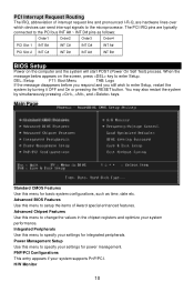
...items of interrupt request line and pronounced I-R-Q, are typically connected to the PCI bus INT A# ~ INT D# pins as time, date etc. Advanced BIOS Features Use this menu for basic system configurations, such as follows: Order1 Order2 Order3 Order4 PCI Slot 1 INT B# INT C# INT D# INT A#... PCI Slot 2 INT C# INT D# INT A# INT B# BIOS Setup Power on the screen, press key to enter Setup. PNP/PCI Configurations This entry appears if your settings for integrated peripherals. Advanced Chipset Features...
...items of interrupt request line and pronounced I-R-Q, are typically connected to the PCI bus INT A# ~ INT D# pins as time, date etc. Advanced BIOS Features Use this menu for basic system configurations, such as follows: Order1 Order2 Order3 Order4 PCI Slot 1 INT B# INT C# INT D# INT A#... PCI Slot 2 INT C# INT D# INT A# INT B# BIOS Setup Power on the screen, press key to enter Setup. PNP/PCI Configurations This entry appears if your settings for integrated peripherals. Advanced Chipset Features...
User Guide
Page 17
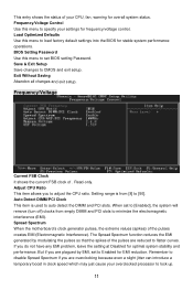
... Spread Spectrum function reduces the EMI generated by EMI, set to flatter curves. Remember to specify your settings for frequency/voltage control. BIOS Setting Password Use this menu to disable Spread Spectrum if you do not have any EMI problem, leave the setting at Disabled for ... introduce a temporary boost in clock speed which may just cause your overclocked processor to minimize the electromagnetic interference (EMI). Spread Spectrum When the motherboard's clock generator pulses, the extreme values (spikes) of . But if you to auto detect the DIMM and PCI slots. This entry shows...
... Spread Spectrum function reduces the EMI generated by EMI, set to flatter curves. Remember to specify your settings for frequency/voltage control. BIOS Setting Password Use this menu to disable Spread Spectrum if you do not have any EMI problem, leave the setting at Disabled for ... introduce a temporary boost in clock speed which may just cause your overclocked processor to minimize the electromagnetic interference (EMI). Spread Spectrum When the motherboard's clock generator pulses, the extreme values (spikes) of . But if you to auto detect the DIMM and PCI slots. This entry shows...
User Guide
Page 65
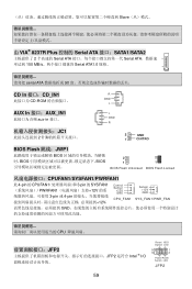
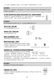
...;口:CD_IN1 R CD-ROM GND L AUX In 接口:AUX_IN1 aux-in 接口。 JC1 2 L GND R 2 GND 1 CINTRO BIOS Flash 跳线:JWP1 BIOS BIOS BIOS 2 2 1 1 BIOS Flash Unlocked BIOS Flash Locked CPUFAN1/SYSFAN1/PWRFAN1 此 4-pin 的 CPUFAN1 3-pin 的 SYSFAN1 PWRFAN1 12V 3-pin 或 4-pin 12V, Control Sensor +12V...
...;口:CD_IN1 R CD-ROM GND L AUX In 接口:AUX_IN1 aux-in 接口。 JC1 2 L GND R 2 GND 1 CINTRO BIOS Flash 跳线:JWP1 BIOS BIOS BIOS 2 2 1 1 BIOS Flash Unlocked BIOS Flash Locked CPUFAN1/SYSFAN1/PWRFAN1 此 4-pin 的 CPUFAN1 3-pin 的 SYSFAN1 PWRFAN1 12V 3-pin 或 4-pin 12V, Control Sensor +12V...
User Guide
Page 77
...;面:CD_IN1 R CD-ROM GND L AUX In 介面:AUX_IN1 aux-in 介面。 JC1 2 L GND R 2 GND 1 CINTRO BIOS Flash 跳線:JWP1 BIOS BIOS BIOS 2 2 1 1 BIOS Flash Unlocked BIOS Flash Locked CPUFAN1/SYSFAN1/PWRFAN1 此 4-pin 的 CPUFAN1 3-pin 的 SYSFAN1 PWRFAN1 12V 3-pin 或 4-pin 12V, Control Sensor +12V...
...;面:CD_IN1 R CD-ROM GND L AUX In 介面:AUX_IN1 aux-in 介面。 JC1 2 L GND R 2 GND 1 CINTRO BIOS Flash 跳線:JWP1 BIOS BIOS BIOS 2 2 1 1 BIOS Flash Unlocked BIOS Flash Locked CPUFAN1/SYSFAN1/PWRFAN1 此 4-pin 的 CPUFAN1 3-pin 的 SYSFAN1 PWRFAN1 12V 3-pin 或 4-pin 12V, Control Sensor +12V...
User Guide
Page 88
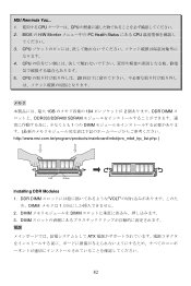
CPU 5. CPU 20 1GB 184 2 DDR DIMM DDR333/DDR400 SDRAM 1 つの DIMM http://www.msi.com.tw/program/products/mainboard/mbd/pro_mbd_trp_list.php ) Volt Notch Installing DDR Modules 1. MSI Reminds You... 1 CPU CPU 2. BIOS の H/W Monitor PC Health Status にある CPU 3. DIMM DIMM 3. DDR DIMM VOLT め、DIMM 1 2. CPU 4. DIMM ATX 82
CPU 5. CPU 20 1GB 184 2 DDR DIMM DDR333/DDR400 SDRAM 1 つの DIMM http://www.msi.com.tw/program/products/mainboard/mbd/pro_mbd_trp_list.php ) Volt Notch Installing DDR Modules 1. MSI Reminds You... 1 CPU CPU 2. BIOS の H/W Monitor PC Health Status にある CPU 3. DIMM DIMM 3. DDR DIMM VOLT め、DIMM 1 2. CPU 4. DIMM ATX 82
User Guide
Page 95
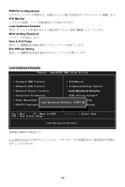
PNP/PCI Configurations PCI H/W Monitor Load Optimized Defaults BIOS BIOS Setting Password Save & Exit Setup CMOS Exit Without Saving CMOS Load Optimized Defaults Load BIOS Default 89
PNP/PCI Configurations PCI H/W Monitor Load Optimized Defaults BIOS BIOS Setting Password Save & Exit Setup CMOS Exit Without Saving CMOS Load Optimized Defaults Load BIOS Default 89


