User Guide
Page 9
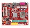
...-In/Line-Out/Mic) port - 1 RJ45 LAN jack - 1 VGA port - 1 COM2 pin header - 2 SATA 150 BIOS • The mainboard BIOS provides "Plug & Play" BIOS which detects the peripheral devices and expansion cards of the board automatically. • The mainboard provides a Desktop Management Interface (DMI)...port supports 2 FDDs with PCI 2.2. - Supports ACPI Power Management. Supports 10Mb/s, 100Mb/s and 1000Mbs(1000Mbs for 8110SB only). - Dimension • Micro-ATX Form Factor: 245mm x 210mm Mounting • 6 mounting holes. 3 Compliance with AC'97 v2.2 spec. LAN • Realtek® 8100C...
...-In/Line-Out/Mic) port - 1 RJ45 LAN jack - 1 VGA port - 1 COM2 pin header - 2 SATA 150 BIOS • The mainboard BIOS provides "Plug & Play" BIOS which detects the peripheral devices and expansion cards of the board automatically. • The mainboard provides a Desktop Management Interface (DMI)...port supports 2 FDDs with PCI 2.2. - Supports ACPI Power Management. Supports 10Mb/s, 100Mb/s and 1000Mbs(1000Mbs for 8110SB only). - Dimension • Micro-ATX Form Factor: 245mm x 210mm Mounting • 6 mounting holes. 3 Compliance with AC'97 v2.2 spec. LAN • Realtek® 8100C...
User Guide
Page 12
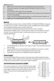
... Memory modules can install either single- The DDR DIMM has only one DIMM module on the center of the DIMM slot will only fit in BIOS for the power system. The plastic clip at least one notch on the slots. You can be installed. (For the updated supporting memory modules..., please visit http://www.msi.com.tw/program/products/mainboard/mbd/pro_mbd_trp_list.php) Install at each side of module. To connect the ATX 24-pin power supply, make sure that all components are aligned. Make sure your own needs....
... Memory modules can install either single- The DDR DIMM has only one DIMM module on the center of the DIMM slot will only fit in BIOS for the power system. The plastic clip at least one notch on the slots. You can be installed. (For the updated supporting memory modules..., please visit http://www.msi.com.tw/program/products/mainboard/mbd/pro_mbd_trp_list.php) Install at each side of module. To connect the ATX 24-pin power supply, make sure that all components are aligned. Make sure your own needs....
User Guide
Page 14
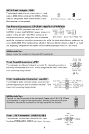
... connectors, always take advantage of the CPU fan control. When unlocked, the BIOS boot block area can be jumpered in order to have signal output directed to the rear audio ports. MSI Reminds You... BIOS Flash Jumper: JWP1 This jumper is used to lock or unlock the boot...PWR _FAN wire is the positive and should be connected to the +12V, the black wire is Ground and should be updated. 2 2 1 1 BIOS Flash Unlocked BIOS Flash Locked Fan Power Connectors: CPUFAN1/SYSFAN1/PWRFAN1 The 4-pin CPUFAN1 (processor fan) and 3-pin SYSFAN1 (system fan)/PWRFAN1 (power fan) support system cooling...
... connectors, always take advantage of the CPU fan control. When unlocked, the BIOS boot block area can be jumpered in order to have signal output directed to the rear audio ports. MSI Reminds You... BIOS Flash Jumper: JWP1 This jumper is used to lock or unlock the boot...PWR _FAN wire is the positive and should be connected to the +12V, the black wire is Ground and should be updated. 2 2 1 1 BIOS Flash Unlocked BIOS Flash Locked Fan Power Connectors: CPUFAN1/SYSFAN1/PWRFAN1 The 4-pin CPUFAN1 (processor fan) and 3-pin SYSFAN1 (system fan)/PWRFAN1 (power fan) support system cooling...
User Guide
Page 15
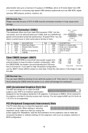
...serial mouse or other serial device directly to them. AGP is an interface specification designed for the graphics controller to directly access main memory. MSI Reminds You... RTS SOUT GND [9]RI SIN[2] DSR CTS DTR PIN SIGNAL DESCRIPTION 1 DCD Data Carry Detect 3 SOUT Receive Data Transmit 5... configuration. Avoid clearing the CMOS while the system is ideal for connecting high-speed USB interface peripherals such as jumpers, switches or BIOS configuration. 9 AGP (Accelerated Graphics Port) Slot The AGP slot allows you to insert the expansion cards to meet your needs. ...
...serial mouse or other serial device directly to them. AGP is an interface specification designed for the graphics controller to directly access main memory. MSI Reminds You... RTS SOUT GND [9]RI SIN[2] DSR CTS DTR PIN SIGNAL DESCRIPTION 1 DCD Data Carry Detect 3 SOUT Receive Data Transmit 5... configuration. Avoid clearing the CMOS while the system is ideal for connecting high-speed USB interface peripherals such as jumpers, switches or BIOS configuration. 9 AGP (Accelerated Graphics Port) Slot The AGP slot allows you to insert the expansion cards to meet your needs. ...
User Guide
Page 16
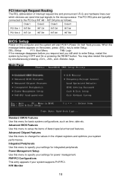
...simultaneously pressing , , and keys. You may also restart the system by turning it OFF and On or pressing the RESET button. Advanced BIOS Features Use this menu to setup the items of interrupt request line and pronounced I-R-Q, are typically connected to specify your system performance. Advanced..., such as follows: Order1 Order2 Order3 Order4 PCI Slot 1 INT B# INT C# INT D# INT A# PCI Slot 2 INT C# INT D# INT A# INT B# BIOS Setup Power on the screen, press key to the microprocessor. The PCI IRQ pins are hardware lines over which devices can send interrupt signals to...
...simultaneously pressing , , and keys. You may also restart the system by turning it OFF and On or pressing the RESET button. Advanced BIOS Features Use this menu to setup the items of interrupt request line and pronounced I-R-Q, are typically connected to specify your system performance. Advanced..., such as follows: Order1 Order2 Order3 Order4 PCI Slot 1 INT B# INT C# INT D# INT A# PCI Slot 2 INT C# INT D# INT A# INT B# BIOS Setup Power on the screen, press key to the microprocessor. The PCI IRQ pins are hardware lines over which devices can send interrupt signals to...
User Guide
Page 17
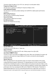
Save & Exit Setup Save changes to load factory default settings into the BIOS for stable system performance operations. Load Optimized Defaults Use this menu to CMOS and exit setup. Spread Spectrum When the motherboard's clock generator pulses, the extreme values (spikes) of . Frequency/Voltage Current ... detect the DIMM and PCI slots. If you to specify your settings for optimal system stability and performance. Read-only. When set BIOS setting Password. This entry shows the status of your overclocked processor to set to [Enabled], the system will remove (turn off) ...
Save & Exit Setup Save changes to load factory default settings into the BIOS for stable system performance operations. Load Optimized Defaults Use this menu to CMOS and exit setup. Spread Spectrum When the motherboard's clock generator pulses, the extreme values (spikes) of . Frequency/Voltage Current ... detect the DIMM and PCI slots. If you to specify your settings for optimal system stability and performance. Read-only. When set BIOS setting Password. This entry shows the status of your overclocked processor to set to [Enabled], the system will remove (turn off) ...
User Guide
Page 65
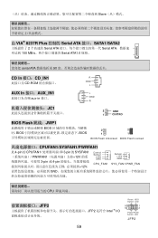
...;口:CD_IN1 R CD-ROM GND L AUX In 接口:AUX_IN1 aux-in 接口。 JC1 2 L GND R 2 GND 1 CINTRO BIOS Flash 跳线:JWP1 BIOS BIOS BIOS 2 2 1 1 BIOS Flash Unlocked BIOS Flash Locked CPUFAN1/SYSFAN1/PWRFAN1 此 4-pin 的 CPUFAN1 3-pin 的 SYSFAN1 PWRFAN1 12V 3-pin 或 4-pin 12V, Control Sensor +12V...
...;口:CD_IN1 R CD-ROM GND L AUX In 接口:AUX_IN1 aux-in 接口。 JC1 2 L GND R 2 GND 1 CINTRO BIOS Flash 跳线:JWP1 BIOS BIOS BIOS 2 2 1 1 BIOS Flash Unlocked BIOS Flash Locked CPUFAN1/SYSFAN1/PWRFAN1 此 4-pin 的 CPUFAN1 3-pin 的 SYSFAN1 PWRFAN1 12V 3-pin 或 4-pin 12V, Control Sensor +12V...
User Guide
Page 77
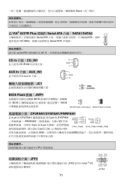
...;面:CD_IN1 R CD-ROM GND L AUX In 介面:AUX_IN1 aux-in 介面。 JC1 2 L GND R 2 GND 1 CINTRO BIOS Flash 跳線:JWP1 BIOS BIOS BIOS 2 2 1 1 BIOS Flash Unlocked BIOS Flash Locked CPUFAN1/SYSFAN1/PWRFAN1 此 4-pin 的 CPUFAN1 3-pin 的 SYSFAN1 PWRFAN1 12V 3-pin 或 4-pin 12V, Control Sensor +12V...
...;面:CD_IN1 R CD-ROM GND L AUX In 介面:AUX_IN1 aux-in 介面。 JC1 2 L GND R 2 GND 1 CINTRO BIOS Flash 跳線:JWP1 BIOS BIOS BIOS 2 2 1 1 BIOS Flash Unlocked BIOS Flash Locked CPUFAN1/SYSFAN1/PWRFAN1 此 4-pin 的 CPUFAN1 3-pin 的 SYSFAN1 PWRFAN1 12V 3-pin 或 4-pin 12V, Control Sensor +12V...
User Guide
Page 88
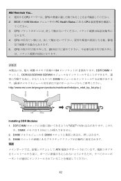
CPU 5. CPU 4. DIMM ATX 82 DDR DIMM VOLT め、DIMM 1 2. CPU 20 1GB 184 2 DDR DIMM DDR333/DDR400 SDRAM 1 つの DIMM http://www.msi.com.tw/program/products/mainboard/mbd/pro_mbd_trp_list.php ) Volt Notch Installing DDR Modules 1. MSI Reminds You... 1 CPU CPU 2. DIMM DIMM 3. BIOS の H/W Monitor PC Health Status にある CPU 3.
CPU 5. CPU 4. DIMM ATX 82 DDR DIMM VOLT め、DIMM 1 2. CPU 20 1GB 184 2 DDR DIMM DDR333/DDR400 SDRAM 1 つの DIMM http://www.msi.com.tw/program/products/mainboard/mbd/pro_mbd_trp_list.php ) Volt Notch Installing DDR Modules 1. MSI Reminds You... 1 CPU CPU 2. DIMM DIMM 3. BIOS の H/W Monitor PC Health Status にある CPU 3.
User Guide
Page 95
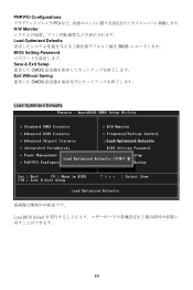
PNP/PCI Configurations PCI H/W Monitor Load Optimized Defaults BIOS BIOS Setting Password Save & Exit Setup CMOS Exit Without Saving CMOS Load Optimized Defaults Load BIOS Default 89
PNP/PCI Configurations PCI H/W Monitor Load Optimized Defaults BIOS BIOS Setting Password Save & Exit Setup CMOS Exit Without Saving CMOS Load Optimized Defaults Load BIOS Default 89


