User Guide
Page 9
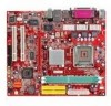
... - 1 VGA port - 1 COM2 pin header - 2 SATA 150 BIOS • The mainboard BIOS provides "Plug & Play" BIOS which detects the peripheral devices and expansion cards of the board automatically. &#...8226; The mainboard provides a Desktop Management Interface (DMI) function which records your mainboard specifications. Compliance with AC'97 v2.2 spec. Supports 10Mb/s, 100Mb/s and 1000Mbs(1000Mbs for 8110SB only). - Supports ACPI Power Management. Dimension • Micro-ATX...
... - 1 VGA port - 1 COM2 pin header - 2 SATA 150 BIOS • The mainboard BIOS provides "Plug & Play" BIOS which detects the peripheral devices and expansion cards of the board automatically. &#...8226; The mainboard provides a Desktop Management Interface (DMI) function which records your mainboard specifications. Compliance with AC'97 v2.2 spec. Supports 10Mb/s, 100Mb/s and 1000Mbs(1000Mbs for 8110SB only). - Supports ACPI Power Management. Dimension • Micro-ATX...
User Guide
Page 12
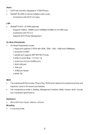
...orientation. 2. Installing DDR Modules Volt Notch 1. The module will be installed. (For the updated supporting memory modules, please visit http://www.msi.com.tw/program/products/mainboard/mbd/pro_mbd_trp_list.php) Install at least one notch on your own needs. Insert the DIMM memory module vertically ...fit in the proper orientation and the pins are installed properly to connect an ATX 24-pin power supply. Therefore, we suggest you to ensure that the mating/unmating durability of H/W Monitor in BIOS for the power system. Check the information in PC Health Status of the...
...orientation. 2. Installing DDR Modules Volt Notch 1. The module will be installed. (For the updated supporting memory modules, please visit http://www.msi.com.tw/program/products/mainboard/mbd/pro_mbd_trp_list.php) Install at least one notch on your own needs. Insert the DIMM memory module vertically ...fit in the proper orientation and the pins are installed properly to connect an ATX 24-pin power supply. Therefore, we suggest you to ensure that the mating/unmating durability of H/W Monitor in BIOS for the power system. Check the information in PC Health Status of the...
User Guide
Page 14
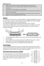
... vendors for electrical connection to the front panel switches and LEDs. AUD_RET_L Key AUD_RET_R AUD_VCC AUD_GND 10 9 21 AUD_FPOUT_L HP_ON AUD_FPOUT_R AUD_MIC_BIAS AUD_MIC MSI Reminds You... 10 9 If you do not want to connect to the front audio header, pins 5 & 6, 9 & 10 have signal... of the CPU fan control. JFP2 is compliant with +12V. Otherwise, the Line-Out connector on BIOS. When unlocked, the BIOS boot block area can be updated. 2 2 1 1 BIOS Flash Unlocked BIOS Flash Locked Fan Power Connectors: CPUFAN1/SYSFAN1/PWRFAN1 The 4-pin CPUFAN1 (processor fan) and 3-pin SYSFAN1...
... vendors for electrical connection to the front panel switches and LEDs. AUD_RET_L Key AUD_RET_R AUD_VCC AUD_GND 10 9 21 AUD_FPOUT_L HP_ON AUD_FPOUT_R AUD_MIC_BIAS AUD_MIC MSI Reminds You... 10 9 If you do not want to connect to the front audio header, pins 5 & 6, 9 & 10 have signal... of the CPU fan control. JFP2 is compliant with +12V. Otherwise, the Line-Out connector on BIOS. When unlocked, the BIOS boot block area can be updated. 2 2 1 1 BIOS Flash Unlocked BIOS Flash Locked Fan Power Connectors: CPUFAN1/SYSFAN1/PWRFAN1 The 4-pin CPUFAN1 (processor fan) and 3-pin SYSFAN1...
User Guide
Page 15
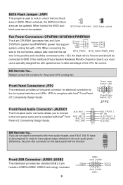
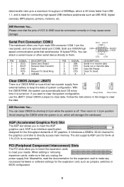
...shorting 2-3 pin while the system is an interface specification designed for connecting high-speed USB interface peripherals such as jumpers, switches or BIOS configuration. 9 AGP is off. When adding or removing expansion cards, make any necessary hardware or software settings for the expansion ...of 480Mbps, which will damage the mainboard. PCI (Peripheral Component Interconnect) Slots The PCI slots allow you unplug the power supply first. MSI Reminds You... With 2 3 the CMOS RAM, the system can attach a serial mouse or other serial device directly to keep the ...
...shorting 2-3 pin while the system is an interface specification designed for connecting high-speed USB interface peripherals such as jumpers, switches or BIOS configuration. 9 AGP is off. When adding or removing expansion cards, make any necessary hardware or software settings for the expansion ...of 480Mbps, which will damage the mainboard. PCI (Peripheral Component Interconnect) Slots The PCI slots allow you unplug the power supply first. MSI Reminds You... With 2 3 the CMOS RAM, the system can attach a serial mouse or other serial device directly to keep the ...
User Guide
Page 16
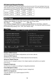
... system configurations, such as follows: Order1 Order2 Order3 Order4 PCI Slot 1 INT B# INT C# INT D# INT A# PCI Slot 2 INT C# INT D# INT A# INT B# BIOS Setup Power on the screen, press key to enter Setup, restart the system by simultaneously pressing , , and keys. Main Page Standard CMOS Features Use this... POST (Power On Self Test) process. You may also restart the system by turning it OFF and On or pressing the RESET button. Advanced BIOS Features Use this menu to the PCI bus INT A# ~ INT D# pins as time, date etc. Power Management Setup Use this menu to...
... system configurations, such as follows: Order1 Order2 Order3 Order4 PCI Slot 1 INT B# INT C# INT D# INT A# PCI Slot 2 INT C# INT D# INT A# INT B# BIOS Setup Power on the screen, press key to enter Setup, restart the system by simultaneously pressing , , and keys. Main Page Standard CMOS Features Use this... POST (Power On Self Test) process. You may also restart the system by turning it OFF and On or pressing the RESET button. Advanced BIOS Features Use this menu to the PCI bus INT A# ~ INT D# pins as time, date etc. Power Management Setup Use this menu to...
User Guide
Page 17
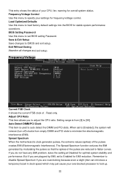
... exit setup. The Spread Spectrum function reduces the EMI generated by EMI, set BIOS setting Password. BIOS Setting Password Use this menu to minimize the electromagnetic interference (EMI). Save & Exit Setup Save changes to [50]. Spread Spectrum When the motherboard's clock generator pulses, the extreme values (spikes) of . But if you to Enabled...
... exit setup. The Spread Spectrum function reduces the EMI generated by EMI, set BIOS setting Password. BIOS Setting Password Use this menu to minimize the electromagnetic interference (EMI). Save & Exit Setup Save changes to [50]. Spread Spectrum When the motherboard's clock generator pulses, the extreme values (spikes) of . But if you to Enabled...
User Guide
Page 65
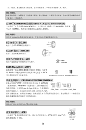
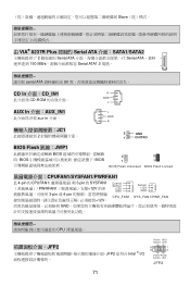
...;口:CD_IN1 R CD-ROM GND L AUX In 接口:AUX_IN1 aux-in 接口。 JC1 2 L GND R 2 GND 1 CINTRO BIOS Flash 跳线:JWP1 BIOS BIOS BIOS 2 2 1 1 BIOS Flash Unlocked BIOS Flash Locked CPUFAN1/SYSFAN1/PWRFAN1 此 4-pin 的 CPUFAN1 3-pin 的 SYSFAN1 PWRFAN1 12V 3-pin 或 4-pin 12V, Control Sensor +12V...
...;口:CD_IN1 R CD-ROM GND L AUX In 接口:AUX_IN1 aux-in 接口。 JC1 2 L GND R 2 GND 1 CINTRO BIOS Flash 跳线:JWP1 BIOS BIOS BIOS 2 2 1 1 BIOS Flash Unlocked BIOS Flash Locked CPUFAN1/SYSFAN1/PWRFAN1 此 4-pin 的 CPUFAN1 3-pin 的 SYSFAN1 PWRFAN1 12V 3-pin 或 4-pin 12V, Control Sensor +12V...
User Guide
Page 77
...;面:CD_IN1 R CD-ROM GND L AUX In 介面:AUX_IN1 aux-in 介面。 JC1 2 L GND R 2 GND 1 CINTRO BIOS Flash 跳線:JWP1 BIOS BIOS BIOS 2 2 1 1 BIOS Flash Unlocked BIOS Flash Locked CPUFAN1/SYSFAN1/PWRFAN1 此 4-pin 的 CPUFAN1 3-pin 的 SYSFAN1 PWRFAN1 12V 3-pin 或 4-pin 12V, Control Sensor +12V...
...;面:CD_IN1 R CD-ROM GND L AUX In 介面:AUX_IN1 aux-in 介面。 JC1 2 L GND R 2 GND 1 CINTRO BIOS Flash 跳線:JWP1 BIOS BIOS BIOS 2 2 1 1 BIOS Flash Unlocked BIOS Flash Locked CPUFAN1/SYSFAN1/PWRFAN1 此 4-pin 的 CPUFAN1 3-pin 的 SYSFAN1 PWRFAN1 12V 3-pin 或 4-pin 12V, Control Sensor +12V...
User Guide
Page 88
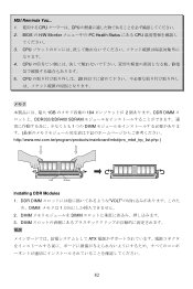
DIMM ATX 82 CPU 5. MSI Reminds You... 1 CPU CPU 2. DIMM DIMM 3. CPU 20 1GB 184 2 DDR DIMM DDR333/DDR400 SDRAM 1 つの DIMM http://www.msi.com.tw/program/products/mainboard/mbd/pro_mbd_trp_list.php ) Volt Notch Installing DDR Modules 1. BIOS の H/W Monitor PC Health Status にある CPU 3. CPU 4. DDR DIMM VOLT め、DIMM 1 2.
DIMM ATX 82 CPU 5. MSI Reminds You... 1 CPU CPU 2. DIMM DIMM 3. CPU 20 1GB 184 2 DDR DIMM DDR333/DDR400 SDRAM 1 つの DIMM http://www.msi.com.tw/program/products/mainboard/mbd/pro_mbd_trp_list.php ) Volt Notch Installing DDR Modules 1. BIOS の H/W Monitor PC Health Status にある CPU 3. CPU 4. DDR DIMM VOLT め、DIMM 1 2.
User Guide
Page 95
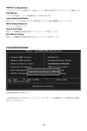
PNP/PCI Configurations PCI H/W Monitor Load Optimized Defaults BIOS BIOS Setting Password Save & Exit Setup CMOS Exit Without Saving CMOS Load Optimized Defaults Load BIOS Default 89
PNP/PCI Configurations PCI H/W Monitor Load Optimized Defaults BIOS BIOS Setting Password Save & Exit Setup CMOS Exit Without Saving CMOS Load Optimized Defaults Load BIOS Default 89


