User Guide
Page 1
... encouraged to try to comply with the emission limits. These limits are designed to part 15 of the FCC Rules. Notice 2 Shielded interface cables and A.C. Micro-Star International MS-7211 This device complies with Part 15 of the FCC rules. Operation is subject to the following two conditions: (1) this device may...
... encouraged to try to comply with the emission limits. These limits are designed to part 15 of the FCC Rules. Notice 2 Shielded interface cables and A.C. Micro-Star International MS-7211 This device complies with Part 15 of the FCC rules. Operation is subject to the following two conditions: (1) this device may...
User Guide
Page 2
.... 2005 ii AMD, Athlon™ Athlon™XP, Thoroughbred™ and Duron™ are registered trademarks of Microsoft Corporation. Netware® is a registered trademark of MICRO-STAR INTERNATIONAL. PCMCIA and CardBus are registered trademarks of the Kensington Technology Group. Copyright Notice The material in this document, but no guarantee is given...
.... 2005 ii AMD, Athlon™ Athlon™XP, Thoroughbred™ and Duron™ are registered trademarks of Microsoft Corporation. Netware® is a registered trademark of MICRO-STAR INTERNATIONAL. PCMCIA and CardBus are registered trademarks of the Kensington Technology Group. Copyright Notice The material in this document, but no guarantee is given...
User Guide
Page 3
Safety Instructions 1. Lay this equipment in an environment unconditioned, storage temperature above 60° C (140°F), it up. 5. The openings on the enclosure are for future reference. 3. Do not place anything over the power cord. 8. Do not leave this equipment on it work well or you can not get the equipment checked by the manufacturer. CAUTION: Danger of the power source and adjust properly 110/220V before inserting any of breakage. 12. Do not cover the openings. 6. All cautions and warnings on card or module. 9. The equipment has dropped and damaged. -...
Safety Instructions 1. Lay this equipment in an environment unconditioned, storage temperature above 60° C (140°F), it up. 5. The openings on the enclosure are for future reference. 3. Do not place anything over the power cord. 8. Do not leave this equipment on it work well or you can not get the equipment checked by the manufacturer. CAUTION: Danger of the power source and adjust properly 110/220V before inserting any of breakage. 12. Do not cover the openings. 6. All cautions and warnings on card or module. 9. The equipment has dropped and damaged. -...
User Guide
Page 7
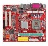
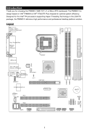
Designed for optimal system efficiency. Layout 1 The PM8M3-V is design based on VIA® P4M800 & VIA® VT8237R Plus chipsets for the Intel® P4 processors supporting Hyper-Threading Technology in the LGA775 package, the PM8M3-V delivers a high performance and professional desktop platform solution. Introduction Thank you for choosing the PM8M3-V (MS-7211 v1.x) Micro-ATX mainboard.
Designed for optimal system efficiency. Layout 1 The PM8M3-V is design based on VIA® P4M800 & VIA® VT8237R Plus chipsets for the Intel® P4 processors supporting Hyper-Threading Technology in the LGA775 package, the PM8M3-V delivers a high performance and professional desktop platform solution. Introduction Thank you for choosing the PM8M3-V (MS-7211 v1.x) Micro-ATX mainboard.
User Guide
Page 8
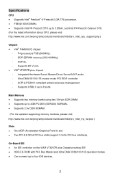
...connect up to 2GB PC3200 (DDR400) SDRAMs. • Supports 2.5v DDR SDRAM. (For the updated supporting memory modules, please visit http://www.msi.com.tw/program/products/mainboard/mbd/pro_mbd_trp_list.php ) Slots • One AGP (Accelerated Graphics Port) 8x slot. • Two PCI 2.2 32...DIMM. • Supports up to 3.2GHz, and Intel P4 Prescott Celeron CPU. (For the latest information about CPU, please visit http://www.msi.com.tw/program/products/mainboard/mbd/pro_mbd_cpu_support.php ) Chipset • VIA® P4M800CE chipset - ACPI & PC2001 compliant enhanced power management - ...
...connect up to 2GB PC3200 (DDR400) SDRAMs. • Supports 2.5v DDR SDRAM. (For the updated supporting memory modules, please visit http://www.msi.com.tw/program/products/mainboard/mbd/pro_mbd_trp_list.php ) Slots • One AGP (Accelerated Graphics Port) 8x slot. • Two PCI 2.2 32...DIMM. • Supports up to 3.2GHz, and Intel P4 Prescott Celeron CPU. (For the latest information about CPU, please visit http://www.msi.com.tw/program/products/mainboard/mbd/pro_mbd_cpu_support.php ) Chipset • VIA® P4M800CE chipset - ACPI & PC2001 compliant enhanced power management - ...
User Guide
Page 9
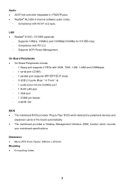
.../s and 1000Mbs(1000Mbs for 8110SB only). - Audio • AC97 link controller integrated in VT8237R plus. • Realtek® ALC655 6-channel software audio codec. - Dimension • Micro-ATX Form Factor: 245mm x 210mm Mounting • 6 mounting holes. 3
.../s and 1000Mbs(1000Mbs for 8110SB only). - Audio • AC97 link controller integrated in VT8237R plus. • Realtek® ALC655 6-channel software audio codec. - Dimension • Micro-ATX Form Factor: 245mm x 210mm Mounting • 6 mounting holes. 3
User Guide
Page 10
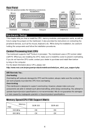
... inadequate operation or beyond product specifications is designed to support overclocking. For the latest information about CPU, please visit http://www.msi.com.tw/program/products/mainboard/mbd/pro_mbd_cpu_support.php. MSI Reminds You... The mainboard uses a CPU socket called LGA775. If you are able to setup the jumpers on the computer. Overclocking...
... inadequate operation or beyond product specifications is designed to support overclocking. For the latest information about CPU, please visit http://www.msi.com.tw/program/products/mainboard/mbd/pro_mbd_cpu_support.php. MSI Reminds You... The mainboard uses a CPU socket called LGA775. If you are able to setup the jumpers on the computer. Overclocking...
User Guide
Page 11
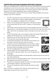
The availability of it for the same direction as the arrows shown. 5. Take out the accompanying CPU Clip (shown in the right) and rotate it depends on the mainboard with the cooler. Please note not to install the CPU & cooler correctly. Align the holes on the CPU packing. 2. Wrong installation will cause the damage to your index finger to allow the whole module to release the CPU, then press down the cooler until its four clips get wedged into the socket, then remove the CPU Clip with the hook under retention tab. 13. Use your thumb and the middle fingers to push the ...
The availability of it for the same direction as the arrows shown. 5. Take out the accompanying CPU Clip (shown in the right) and rotate it depends on the mainboard with the cooler. Please note not to install the CPU & cooler correctly. Align the holes on the CPU packing. 2. Wrong installation will cause the damage to your index finger to allow the whole module to release the CPU, then press down the cooler until its four clips get wedged into the socket, then remove the CPU Clip with the hook under retention tab. 13. Use your thumb and the middle fingers to push the ...
User Guide
Page 12
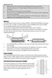
... has only one DIMM module on the slots in BIOS for the power system. To connect the ATX 24-pin power supply, make sure that the mating/unmating durability of H/W Monitor in any order. MSI Reminds You... 1. Make sure your CPU cooler is firmly installed before turning on the center of... the power supply is not installed, always protect your own needs. Check the information in PC Health Status of the CPU is suggested. 12 24 ATX 24-Pin Power Connector: ...
... has only one DIMM module on the slots in BIOS for the power system. To connect the ATX 24-pin power supply, make sure that the mating/unmating durability of H/W Monitor in any order. MSI Reminds You... 1. Make sure your CPU cooler is firmly installed before turning on the center of... the power supply is not installed, always protect your own needs. Check the information in PC Health Status of the CPU is suggested. 12 24 ATX 24-Pin Power Connector: ...
User Guide
Page 13
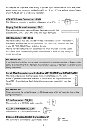
...controlled by setting its jumper. The ports supper 1st generation Serial ATA data rates of data during transmission. You may use the 20-pin ATX power supply, please plug your power supply along with Serial ATA 1.0 specifications. You can connect a Master and a Slave drive. Each Serial... ATA connector can connect to IDE1. MSI Reminds You... If you'd like to use the 20-pin ATX power supply as you must configure second hard drive to a 2-pin chassis switch. 2 GND 1 CINTRO...
...controlled by setting its jumper. The ports supper 1st generation Serial ATA data rates of data during transmission. You may use the 20-pin ATX power supply, please plug your power supply along with Serial ATA 1.0 specifications. You can connect a Master and a Slave drive. Each Serial... ATA connector can connect to IDE1. MSI Reminds You... If you'd like to use the 20-pin ATX power supply as you must configure second hard drive to a 2-pin chassis switch. 2 GND 1 CINTRO...
User Guide
Page 14
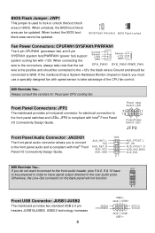
...: CPUFAN1/SYSFAN1/PWRFAN1 The 4-pin CPUFAN1 (processor fan) and 3-pin SYSFAN1 (system fan)/PWRFAN1 (power fan) support system cooling fan with +12V. MSI Reminds You... JFP2 is compliant with Intel® Front Panel I /O Connectivity Design Guide. USB2.0 technology increases 8 (9)Key (10)USB0C USB0+ GND...in order to have to be connected to the rear audio ports. AUD_RET_L Key AUD_RET_R AUD_VCC AUD_GND 10 9 21 AUD_FPOUT_L HP_ON AUD_FPOUT_R AUD_MIC_BIAS AUD_MIC MSI Reminds You... 10 9 If you do not want to connect to the front audio header, pins 5 & 6, 9 & 10 have ...
...: CPUFAN1/SYSFAN1/PWRFAN1 The 4-pin CPUFAN1 (processor fan) and 3-pin SYSFAN1 (system fan)/PWRFAN1 (power fan) support system cooling fan with +12V. MSI Reminds You... JFP2 is compliant with Intel® Front Panel I /O Connectivity Design Guide. USB2.0 technology increases 8 (9)Key (10)USB0C USB0+ GND...in order to have to be connected to the rear audio ports. AUD_RET_L Key AUD_RET_R AUD_VCC AUD_GND 10 9 21 AUD_FPOUT_L HP_ON AUD_FPOUT_R AUD_MIC_BIAS AUD_MIC MSI Reminds You... 10 9 If you do not want to connect to the front audio header, pins 5 & 6, 9 & 10 have ...
User Guide
Page 15
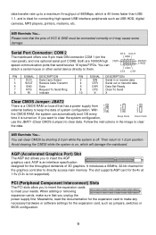
... on board that the pins of 3D graphics. AGP is off. You can attach a serial mouse or other serial device directly to 1-2 pin position. MSI Reminds You... Then return to them. Avoid clearing the CMOS while the system is a CMOS RAM on , which is 40 times faster than USB 1.1,...is turned on the rear panel), and one 9-pin male DIN connector COM 1 (on . data transfer rate up to insert the AGP graphics card. MSI Reminds You... AGP (Accelerated Graphics Port) Slot The AGP slot allows you to insert the expansion cards to directly access main memory. It introduces a 66MHz...
... on board that the pins of 3D graphics. AGP is off. You can attach a serial mouse or other serial device directly to 1-2 pin position. MSI Reminds You... Then return to them. Avoid clearing the CMOS while the system is a CMOS RAM on , which is 40 times faster than USB 1.1,...is turned on the rear panel), and one 9-pin male DIN connector COM 1 (on . data transfer rate up to insert the AGP graphics card. MSI Reminds You... AGP (Accelerated Graphics Port) Slot The AGP slot allows you to insert the expansion cards to directly access main memory. It introduces a 66MHz...
User Guide
Page 16
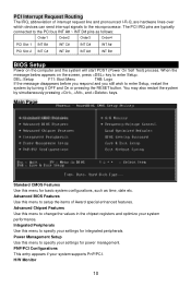
When the message below appears on the computer and the system will start POST (Power On Self Test) process. Advanced BIOS Features Use this menu to enter Setup. Integrated Peripherals Use this menu to specify your settings for basic system configurations, such as follows: Order1 Order2 Order3 Order4 PCI Slot 1 INT B# INT C# INT D# INT A# PCI Slot 2 INT C# INT D# INT A# INT B# BIOS Setup Power on the screen, press key to setup the items of interrupt request line and pronounced I-R-Q, are typically connected to enter Setup, restart the system by simultaneously ...
When the message below appears on the computer and the system will start POST (Power On Self Test) process. Advanced BIOS Features Use this menu to enter Setup. Integrated Peripherals Use this menu to specify your settings for basic system configurations, such as follows: Order1 Order2 Order3 Order4 PCI Slot 1 INT B# INT C# INT D# INT A# PCI Slot 2 INT C# INT D# INT A# INT B# BIOS Setup Power on the screen, press key to setup the items of interrupt request line and pronounced I-R-Q, are typically connected to enter Setup, restart the system by simultaneously ...
User Guide
Page 17
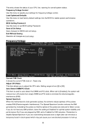
... that the spikes of your CPU, fan, warning for frequency/voltage control. Exit Without Saving Abandon all changes and exit setup. Spread Spectrum When the motherboard's clock generator pulses, the extreme values (spikes) of . BIOS Setting Password Use this menu to specify your overclocked processor to lock up. 11 Frequency/Voltage...
... that the spikes of your CPU, fan, warning for frequency/voltage control. Exit Without Saving Abandon all changes and exit setup. Spread Spectrum When the motherboard's clock generator pulses, the extreme values (spikes) of . BIOS Setting Password Use this menu to specify your overclocked processor to lock up. 11 Frequency/Voltage...
User Guide
Page 18
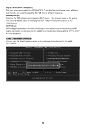
Setting options: 1.5V to this setting may be affected. Adjust CPU/AGP/PCI Frequency This item allows you to select the CPU/AGP/PCI Front Side Bus clock frequency (in the field, allowing you to increase the performance of your AGP display card when overclocking, but the stability may cause a stability issue, so changing the DDR voltage for long-term purpose is adjustable in MHz) and overclock the processor by the mainboard manufacturer for the stable performance. 12 Load Optimized Defaults You can increase the DDR speed. Memory Voltage Adjusting the DDR voltage can load the ...
Setting options: 1.5V to this setting may be affected. Adjust CPU/AGP/PCI Frequency This item allows you to select the CPU/AGP/PCI Front Side Bus clock frequency (in the field, allowing you to increase the performance of your AGP display card when overclocking, but the stability may cause a stability issue, so changing the DDR voltage for long-term purpose is adjustable in MHz) and overclock the processor by the mainboard manufacturer for the stable performance. 12 Load Optimized Defaults You can increase the DDR speed. Memory Voltage Adjusting the DDR voltage can load the ...
User Guide
Page 64
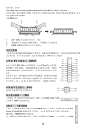
http://www.msi.com.tw/program/products/mainboard/mbd/pro_mbd_trp_list.php DDR 内存 Volt Notch 1. DDR DIMM 2. 将 DDR DDR 3. DIMM ATX 300W 12 24 ATX 24-Pin CONN1 ATX 24-Pin ATX 24-Pin 20-pin 的 ATX 20-pin 的 ATX pin 1 和 pin 13 pin 11, 12, 23 和 24 NC +...12V 5VSB PWR OK GND +5V GND +5V GND +3.3V +3.3V 1 13 GND +5V +5V +5V Res GND GND GND PS-ON# GND -12V +3.3V ATX 12V JPW1 12V 此 12V CPU 供电。 12V FDD1 1 FDD1,支持 360K, 720K, 1.2M, 1.44M 和 2.88M 42 31...
http://www.msi.com.tw/program/products/mainboard/mbd/pro_mbd_trp_list.php DDR 内存 Volt Notch 1. DDR DIMM 2. 将 DDR DDR 3. DIMM ATX 300W 12 24 ATX 24-Pin CONN1 ATX 24-Pin ATX 24-Pin 20-pin 的 ATX 20-pin 的 ATX pin 1 和 pin 13 pin 11, 12, 23 和 24 NC +...12V 5VSB PWR OK GND +5V GND +5V GND +3.3V +3.3V 1 13 GND +5V +5V +5V Res GND GND GND PS-ON# GND -12V +3.3V ATX 12V JPW1 12V 此 12V CPU 供电。 12V FDD1 1 FDD1,支持 360K, 720K, 1.2M, 1.44M 和 2.88M 42 31...
User Guide
Page 65
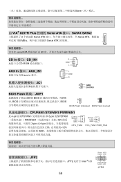
Slave 由 VIA® 8237R Plus 控制的 Serial ATA 接口:SATA1/SATA2 2 Serial ATA Serial ATA 150 MB/s Serial ATA1.0 规格。 serial ATA 90 CD In 接口:CD_IN1 R CD-ROM GND L AUX In 接口:AUX_IN1 aux-in 接口。 JC1 2 L GND R 2 GND 1 CINTRO BIOS Flash 跳线:JWP1 BIOS BIOS BIOS 2 2 1 1 BIOS Flash Unlocked BIOS Flash Locked CPUFAN1/SYSFAN1/PWRFAN1 此 4-pin 的 CPUFAN1 3-pin 的 SYSFAN1 PWRFAN1 12V 3-...
Slave 由 VIA® 8237R Plus 控制的 Serial ATA 接口:SATA1/SATA2 2 Serial ATA Serial ATA 150 MB/s Serial ATA1.0 规格。 serial ATA 90 CD In 接口:CD_IN1 R CD-ROM GND L AUX In 接口:AUX_IN1 aux-in 接口。 JC1 2 L GND R 2 GND 1 CINTRO BIOS Flash 跳线:JWP1 BIOS BIOS BIOS 2 2 1 1 BIOS Flash Unlocked BIOS Flash Locked CPUFAN1/SYSFAN1/PWRFAN1 此 4-pin 的 CPUFAN1 3-pin 的 SYSFAN1 PWRFAN1 12V 3-...
User Guide
Page 66
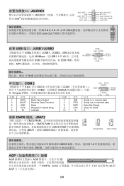
VCC(1) VCC(2) GND USB1USB1+ VCC 和 GND COM 2 RTS SOUT GND 1 个 9-pin 公头 DIN COM1 9]RI 和另 1 COM2 16550A SIN[2] 发 16 bytes FIFO 针脚 信号 定义 针脚 信号 定义 DSR CTS DTR 1 DCD Data Carry Detect 3 SOUT Receive Data Transmit 5 GND Data 7 RTS Request To Send Ring 9 RI Indicate 2 SIN Serial in or receive data 4 DTR Serial out or transmit data 6 DSR Data Set Ready 8 CTS Clear To Send 10 X X 清除 CMOS 跳...
VCC(1) VCC(2) GND USB1USB1+ VCC 和 GND COM 2 RTS SOUT GND 1 个 9-pin 公头 DIN COM1 9]RI 和另 1 COM2 16550A SIN[2] 发 16 bytes FIFO 针脚 信号 定义 针脚 信号 定义 DSR CTS DTR 1 DCD Data Carry Detect 3 SOUT Receive Data Transmit 5 GND Data 7 RTS Request To Send Ring 9 RI Indicate 2 SIN Serial in or receive data 4 DTR Serial out or transmit data 6 DSR Data Set Ready 8 CTS Clear To Send 10 X X 清除 CMOS 跳...
User Guide
Page 76
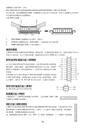
http://www.msi.com.tw/program/products/mainboard/mbd/pro_mbd_trp_list.php DDR 記憶體 Volt Notch 1. DIMM ATX 300W 12 24 ATX 24-Pin CONN1 ATX 24-Pin ATX 24-Pin 20-pin 的 ATX 20-pin 的 ATX pin 1 和 pin 13 pin 11, 12, 23 和 24 NC +12V +12V 5VSB PWR OK GND... +5V GND +5V GND +3.3V +3.3V GND +5V +5V +5V Res GND GND GND PS-ON# GND -12V +3.3V 1 13 ATX 12V JPW1 12V 此 12V CPU 供電。 12V FDD1 1 FDD1,支援 360K, 720K, 1.2M, 1.44M 和 2.88M 42 31 GND...
http://www.msi.com.tw/program/products/mainboard/mbd/pro_mbd_trp_list.php DDR 記憶體 Volt Notch 1. DIMM ATX 300W 12 24 ATX 24-Pin CONN1 ATX 24-Pin ATX 24-Pin 20-pin 的 ATX 20-pin 的 ATX pin 1 和 pin 13 pin 11, 12, 23 和 24 NC +12V +12V 5VSB PWR OK GND... +5V GND +5V GND +3.3V +3.3V GND +5V +5V +5V Res GND GND GND PS-ON# GND -12V +3.3V 1 13 ATX 12V JPW1 12V 此 12V CPU 供電。 12V FDD1 1 FDD1,支援 360K, 720K, 1.2M, 1.44M 和 2.88M 42 31 GND...
User Guide
Page 77
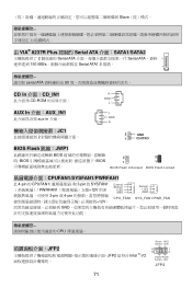
Slave 由 VIA® 8237R Plus 控制的 Serial ATA 介面:SATA1/SATA2 2 Serial ATA Serial ATA 150 MB/s Serial ATA1.0 規格。 serial ATA 90 CD In 介面:CD_IN1 R CD-ROM GND L AUX In 介面:AUX_IN1 aux-in 介面。 JC1 2 L GND R 2 GND 1 CINTRO BIOS Flash 跳線:JWP1 BIOS BIOS BIOS 2 2 1 1 BIOS Flash Unlocked BIOS Flash Locked CPUFAN1/SYSFAN1/PWRFAN1 此 4-pin 的 CPUFAN1 3-pin 的 SYSFAN1 PWRFAN1 12V 3-...
Slave 由 VIA® 8237R Plus 控制的 Serial ATA 介面:SATA1/SATA2 2 Serial ATA Serial ATA 150 MB/s Serial ATA1.0 規格。 serial ATA 90 CD In 介面:CD_IN1 R CD-ROM GND L AUX In 介面:AUX_IN1 aux-in 介面。 JC1 2 L GND R 2 GND 1 CINTRO BIOS Flash 跳線:JWP1 BIOS BIOS BIOS 2 2 1 1 BIOS Flash Unlocked BIOS Flash Locked CPUFAN1/SYSFAN1/PWRFAN1 此 4-pin 的 CPUFAN1 3-pin 的 SYSFAN1 PWRFAN1 12V 3-...
