User Guide
Page 1
... be determined by turning the equipment off and on, the user is encouraged to try to correct the interference by the party responsible for help. Micro-Star International MS-7211 This device complies with the limits for a class B digital device, pursuant to part 15 of the FCC rules. Notice 1 The changes...
... be determined by turning the equipment off and on, the user is encouraged to try to correct the interference by the party responsible for help. Micro-Star International MS-7211 This device complies with the limits for a class B digital device, pursuant to part 15 of the FCC rules. Notice 1 The changes...
User Guide
Page 2
....0 First release V1.1 Japanese included V1.2 Remove the RoHS Logo Date September. 2005 October. 2005 December. 2005 ii PCMCIA and CardBus are registered trademarks of MICRO-STAR INTERNATIONAL. Copyright Notice The material in the United States and/or other countries. PS/2 and OS® 2 are registered trademarks or trademarks of NVIDIA...
....0 First release V1.1 Japanese included V1.2 Remove the RoHS Logo Date September. 2005 October. 2005 December. 2005 ii PCMCIA and CardBus are registered trademarks of MICRO-STAR INTERNATIONAL. Copyright Notice The material in the United States and/or other countries. PS/2 and OS® 2 are registered trademarks or trademarks of NVIDIA...
User Guide
Page 3
Never pour any liquid into the equipment. - Liquid has penetrated into the opening that people can not get the equipment checked by the manufacturer. The equipment has dropped and damaged. - The equipment has obvious sign of explosion if battery is damaged. - iii Keep this equipment on a reliable flat surface before setting it work well or you can not step on card or module. 9. Do not cover the openings. 6. The equipment has been exposed to the power inlet. 7. Lay this equipment away from overheating. Make sure the voltage of the power source and ...
Never pour any liquid into the equipment. - Liquid has penetrated into the opening that people can not get the equipment checked by the manufacturer. The equipment has dropped and damaged. - The equipment has obvious sign of explosion if battery is damaged. - iii Keep this equipment on a reliable flat surface before setting it work well or you can not step on card or module. 9. Do not cover the openings. 6. The equipment has been exposed to the power inlet. 7. Lay this equipment away from overheating. Make sure the voltage of the power source and ...
User Guide
Page 7
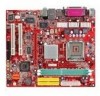
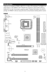
Layout 1 The PM8M3-V is design based on VIA® P4M800 & VIA® VT8237R Plus chipsets for the Intel® P4 processors supporting Hyper-Threading Technology in the LGA775 package, the PM8M3-V delivers a high performance and professional desktop platform solution. Designed for optimal system efficiency. Introduction Thank you for choosing the PM8M3-V (MS-7211 v1.x) Micro-ATX mainboard.
Layout 1 The PM8M3-V is design based on VIA® P4M800 & VIA® VT8237R Plus chipsets for the Intel® P4 processors supporting Hyper-Threading Technology in the LGA775 package, the PM8M3-V delivers a high performance and professional desktop platform solution. Designed for optimal system efficiency. Introduction Thank you for choosing the PM8M3-V (MS-7211 v1.x) Micro-ATX mainboard.
User Guide
Page 8
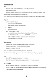
... Can connect up to 2GB PC3200 (DDR400) SDRAMs. • Supports 2.5v DDR SDRAM. (For the updated supporting memory modules, please visit http://www.msi.com.tw/program/products/mainboard/mbd/pro_mbd_trp_list.php ) Slots • One AGP (Accelerated Graphics Port) 8x slot. • Two PCI 2.2 32-bit PCI...DDR DIMM. • Supports up to 3.2GHz, and Intel P4 Prescott Celeron CPU. (For the latest information about CPU, please visit http://www.msi.com.tw/program/products/mainboard/mbd/pro_mbd_cpu_support.php ) Chipset • VIA® P4M800CE chipset - AGP 8x. - Ultra DMA 66/100/133 ...
... Can connect up to 2GB PC3200 (DDR400) SDRAMs. • Supports 2.5v DDR SDRAM. (For the updated supporting memory modules, please visit http://www.msi.com.tw/program/products/mainboard/mbd/pro_mbd_trp_list.php ) Slots • One AGP (Accelerated Graphics Port) 8x slot. • Two PCI 2.2 32-bit PCI...DDR DIMM. • Supports up to 3.2GHz, and Intel P4 Prescott Celeron CPU. (For the latest information about CPU, please visit http://www.msi.com.tw/program/products/mainboard/mbd/pro_mbd_cpu_support.php ) Chipset • VIA® P4M800CE chipset - AGP 8x. - Ultra DMA 66/100/133 ...
User Guide
Page 9
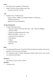
... peripheral devices and expansion cards of the board automatically. • The mainboard provides a Desktop Management Interface (DMI) function which records your mainboard specifications. Dimension • Micro-ATX Form Factor: 245mm x 210mm Mounting • 6 mounting holes. 3 Audio • AC97 link controller integrated in VT8237R plus. • Realtek® ALC655 6-channel software audio codec...
... peripheral devices and expansion cards of the board automatically. • The mainboard provides a Desktop Management Interface (DMI) function which records your mainboard specifications. Dimension • Micro-ATX Form Factor: 245mm x 210mm Mounting • 6 mounting holes. 3 Audio • AC97 link controller integrated in VT8237R plus. • Realtek® ALC655 6-channel software audio codec...
User Guide
Page 10
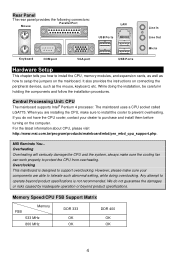
...designed to support overclocking. Overclocking This mainboard is not recommended. For the latest information about CPU, please visit http://www.msi.com.tw/program/products/mainboard/mbd/pro_mbd_cpu_support.php. If you are able to tolerate such abnormal setting, while doing the ... holding the components and follow the installation procedures. Central Processing Unit: CPU The mainboard supports Intel® Pentium 4 processor. MSI Reminds You... Any attempt to operate beyond product specifications. Overheating Overheating will seriously damage the CPU and the system, always make...
...designed to support overclocking. Overclocking This mainboard is not recommended. For the latest information about CPU, please visit http://www.msi.com.tw/program/products/mainboard/mbd/pro_mbd_cpu_support.php. If you are able to tolerate such abnormal setting, while doing the ... holding the components and follow the installation procedures. Central Processing Unit: CPU The mainboard supports Intel® Pentium 4 processor. MSI Reminds You... Any attempt to operate beyond product specifications. Overheating Overheating will seriously damage the CPU and the system, always make...
User Guide
Page 11
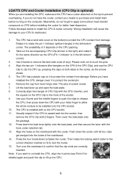
Rotate it to touch the pins. 4. Use 2 hands to make sure the CPU has a cooler attached on the top to lock the hooks. 15. Note: If you do not forget to purchase and install them before installing the cooler for better heat dispersion. If you want to uninstall the CPU, align the 4 points (see Point 8 for the same direction as the arrows shown. 5. The CPU has a land side cover on the bottom to lift up the CPU. 5 Please note not to protect the contact from lever hinge side. The CPU has a plastic cap on it to remove the land side cover (if any). Before you are...
Rotate it to touch the pins. 4. Use 2 hands to make sure the CPU has a cooler attached on the top to lock the hooks. 15. Note: If you do not forget to purchase and install them before installing the cooler for better heat dispersion. If you want to uninstall the CPU, align the 4 points (see Point 8 for the same direction as the arrows shown. 5. The CPU has a land side cover on the bottom to lift up the CPU. 5 Please note not to protect the contact from lever hinge side. The CPU has a plastic cap on it to remove the land side cover (if any). Before you are...
User Guide
Page 12
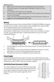
... push down the power supply firmly into the DIMM slot. You can be installed. (For the updated supporting memory modules, please visit http://www.msi.com.tw/program/products/mainboard/mbd/pro_mbd_trp_list.php) Install at each side of the CPU is deeply inserted in BIOS for the power system. Then...CPU too often. Memory The mainboard provides two 184-pin unbuffered DDR333 / DDR400 DDR SDRAM, and supports the memory size up to connect an ATX 24-pin power supply. or double-sided modules to ensure that the mating/unmating durability of the DIMM slot will only fit in the proper...
... push down the power supply firmly into the DIMM slot. You can be installed. (For the updated supporting memory modules, please visit http://www.msi.com.tw/program/products/mainboard/mbd/pro_mbd_trp_list.php) Install at each side of the CPU is deeply inserted in BIOS for the power system. Then...CPU too often. Memory The mainboard provides two 184-pin unbuffered DDR333 / DDR400 DDR SDRAM, and supports the memory size up to connect an ATX 24-pin power supply. or double-sided modules to ensure that the mating/unmating durability of the DIMM slot will only fit in the proper...
User Guide
Page 13
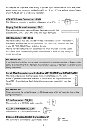
... second drive to Slave mode by setting its jumper. If you 'd like . Each Serial ATA connector can connect to use the 20-pin ATX power supply as you must configure second hard drive to Slave mode by setting the jumper accordingly. CD In Connector: CD_IN1 R The connector is...design on one cable, you like to 1 hard disk device. Refer to four hard disk drives, CD-ROM, 120MB Floppy and other devices. MSI Reminds You... MSI Reminds You... Serial ATA Connectors controlled by hard disk vendors for audio aux-in a 90-degree angle, which will cause the loss of 150MB...
... second drive to Slave mode by setting its jumper. If you 'd like . Each Serial ATA connector can connect to use the 20-pin ATX power supply as you must configure second hard drive to Slave mode by setting the jumper accordingly. CD In Connector: CD_IN1 R The connector is...design on one cable, you like to 1 hard disk device. Refer to four hard disk drives, CD-ROM, 120MB Floppy and other devices. MSI Reminds You... MSI Reminds You... Serial ATA Connectors controlled by hard disk vendors for audio aux-in a 90-degree angle, which will cause the loss of 150MB...
User Guide
Page 14
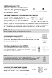
MSI Reminds You... Always consult the vendors for electrical connection to take note that the red Control Sensor +12V GND CPU_FAN1 Sensor +12V GND SY S _ FAN 1/ ...- VCC(1) VCC(2) GND USB1USB1+ JFP2 is Ground and should be connected to GND. AUD_RET_L Key AUD_RET_R AUD_VCC AUD_GND 10 9 21 AUD_FPOUT_L HP_ON AUD_FPOUT_R AUD_MIC_BIAS AUD_MIC MSI Reminds You... 10 9 If you to connect to the front panel audio and is used to the rear audio ports. Otherwise, the Line-Out connector...
MSI Reminds You... Always consult the vendors for electrical connection to take note that the red Control Sensor +12V GND CPU_FAN1 Sensor +12V GND SY S _ FAN 1/ ...- VCC(1) VCC(2) GND USB1USB1+ JFP2 is Ground and should be connected to GND. AUD_RET_L Key AUD_RET_R AUD_VCC AUD_GND 10 9 21 AUD_FPOUT_L HP_ON AUD_FPOUT_R AUD_MIC_BIAS AUD_MIC MSI Reminds You... 10 9 If you to connect to the front panel audio and is used to the rear audio ports. Otherwise, the Line-Out connector...
User Guide
Page 15
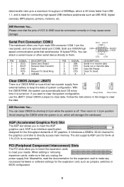
...You can clear CMOS by shorting 2-3 pin while the system is a CMOS RAM on the rear panel), and one optional serial port COM2. MSI Reminds You... AGP (Accelerated Graphics Port) Slot The AGP slot allows you to insert the expansion cards to meet your needs. PCI (Peripheral Component...SIGNAL DESCRIPTION 2 SIN Serial in the image to clear the data. It introduces a 66MHz, 32-bit channel for the throughput demands of 3D graphics. MSI Reminds You... You can automatically boot OS every time it may cause some damage Serial Port Connector: COM 2 The mainboard offers one 9-pin male ...
...You can clear CMOS by shorting 2-3 pin while the system is a CMOS RAM on the rear panel), and one optional serial port COM2. MSI Reminds You... AGP (Accelerated Graphics Port) Slot The AGP slot allows you to insert the expansion cards to meet your needs. PCI (Peripheral Component...SIGNAL DESCRIPTION 2 SIN Serial in the image to clear the data. It introduces a 66MHz, 32-bit channel for the throughput demands of 3D graphics. MSI Reminds You... You can automatically boot OS every time it may cause some damage Serial Port Connector: COM 2 The mainboard offers one 9-pin male ...
User Guide
Page 16
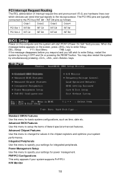
The PCI IRQ pins are hardware lines over which devices can send interrupt signals to enter Setup, restart the system by simultaneously pressing , , and keys. You may also restart the system by turning it OFF and On or pressing the RESET button. Main Page Standard CMOS Features Use this menu to specify your settings for integrated peripherals. Power Management Setup Use this menu for power management. Advanced Chipset Features Use this menu to change the values in the chipset registers and optimize your system supports PnP/PCI. Integrated Peripherals Use this menu to ...
The PCI IRQ pins are hardware lines over which devices can send interrupt signals to enter Setup, restart the system by simultaneously pressing , , and keys. You may also restart the system by turning it OFF and On or pressing the RESET button. Main Page Standard CMOS Features Use this menu to specify your settings for integrated peripherals. Power Management Setup Use this menu for power management. Advanced Chipset Features Use this menu to change the values in the chipset registers and optimize your system supports PnP/PCI. Integrated Peripherals Use this menu to ...
User Guide
Page 17
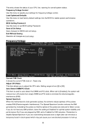
... Save changes to auto detect the DIMM and PCI slots. Setting range is used to CMOS and exit setup. Read-only. Spread Spectrum When the motherboard's clock generator pulses, the extreme values (spikes) of . This entry shows the status of your CPU, fan, warning for EMI reduction.
... Save changes to auto detect the DIMM and PCI slots. Setting range is used to CMOS and exit setup. Read-only. Spread Spectrum When the motherboard's clock generator pulses, the extreme values (spikes) of . This entry shows the status of your CPU, fan, warning for EMI reduction.
User Guide
Page 18
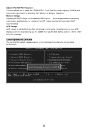
Setting options: 1.5V to this setting may be affected. Any changes made to 1.85V at 0.05V increment. AGP Voltage AGP voltage is adjustable in the field, allowing you to select the CPU/AGP/PCI Front Side Bus clock frequency (in MHz) and overclock the processor by the mainboard manufacturer for long-term purpose is NOT recommended. Load Optimized Defaults You can increase the DDR speed. Adjust CPU/AGP/PCI Frequency This item allows you to a higher frequency. Memory Voltage Adjusting the DDR voltage can load the default values provided by adjusting the FSB clock to increase ...
Setting options: 1.5V to this setting may be affected. Any changes made to 1.85V at 0.05V increment. AGP Voltage AGP voltage is adjustable in the field, allowing you to select the CPU/AGP/PCI Front Side Bus clock frequency (in MHz) and overclock the processor by the mainboard manufacturer for long-term purpose is NOT recommended. Load Optimized Defaults You can increase the DDR speed. Adjust CPU/AGP/PCI Frequency This item allows you to a higher frequency. Memory Voltage Adjusting the DDR voltage can load the default values provided by adjusting the FSB clock to increase ...
User Guide
Page 64
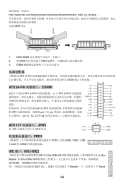
... +12V 5VSB PWR OK GND +5V GND +5V GND +3.3V +3.3V 1 13 GND +5V +5V +5V Res GND GND GND PS-ON# GND -12V +3.3V ATX 12V JPW1 12V 此 12V CPU 供电。 12V FDD1 1 FDD1,支持 360K, 720K, 1.2M, 1.44M 和 2.88M 42 31 GND GND... DMA 66/100/133 4 CD-ROM、120MB IDE1 接口。IDE1 1 个 Master 1 个 Slave 58 DDR DIMM 2. 将 DDR DDR 3. http://www.msi.com.tw/program/products/mainboard/mbd/pro_mbd_trp_list.php DDR 内存 Volt Notch 1.
... +12V 5VSB PWR OK GND +5V GND +5V GND +3.3V +3.3V 1 13 GND +5V +5V +5V Res GND GND GND PS-ON# GND -12V +3.3V ATX 12V JPW1 12V 此 12V CPU 供电。 12V FDD1 1 FDD1,支持 360K, 720K, 1.2M, 1.44M 和 2.88M 42 31 GND GND... DMA 66/100/133 4 CD-ROM、120MB IDE1 接口。IDE1 1 个 Master 1 个 Slave 58 DDR DIMM 2. 将 DDR DDR 3. http://www.msi.com.tw/program/products/mainboard/mbd/pro_mbd_trp_list.php DDR 内存 Volt Notch 1.
User Guide
Page 65
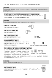
Slave 由 VIA® 8237R Plus 控制的 Serial ATA 接口:SATA1/SATA2 2 Serial ATA Serial ATA 150 MB/s Serial ATA1.0 规格。 serial ATA 90 CD In 接口:CD_IN1 R CD-ROM GND L AUX In 接口:AUX_IN1 aux-in 接口。 JC1 2 L GND R 2 GND 1 CINTRO BIOS Flash 跳线:JWP1 BIOS BIOS BIOS 2 2 1 1 BIOS Flash Unlocked BIOS Flash Locked CPUFAN1/SYSFAN1/PWRFAN1 此 4-pin 的 CPUFAN1 3-pin 的 SYSFAN1 PWRFAN1 12V 3-...
Slave 由 VIA® 8237R Plus 控制的 Serial ATA 接口:SATA1/SATA2 2 Serial ATA Serial ATA 150 MB/s Serial ATA1.0 规格。 serial ATA 90 CD In 接口:CD_IN1 R CD-ROM GND L AUX In 接口:AUX_IN1 aux-in 接口。 JC1 2 L GND R 2 GND 1 CINTRO BIOS Flash 跳线:JWP1 BIOS BIOS BIOS 2 2 1 1 BIOS Flash Unlocked BIOS Flash Locked CPUFAN1/SYSFAN1/PWRFAN1 此 4-pin 的 CPUFAN1 3-pin 的 SYSFAN1 PWRFAN1 12V 3-...
User Guide
Page 66
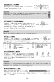
JAUDIO1 AUD_RET_L 10 9 AUD_FPOUT_L JAUDIO1 Key AUD_RET_R 符合 Intel® I/O AUD_VCC AUD_GND HP_ON AUD_FPOUT_R AUD_MIC_BIAS AUD_MIC 21 10 9 5 & 6, 9 & 10 Line-Out 21 前置 USB 接口:JUSB1/JUSB2 2 个 USB2.0 的接口 JUSB1、JUSB2。USB 2.0 480Mbps,是 USB1.1 的 40 USB USB HDD MP3 (9)Key (10)USB0C USB0+ GND USB0- VCC(1) VCC(2) GND USB1USB1+ VCC 和 GND COM 2 RTS SOUT GND 1 个 9-pin 公头 DIN COM1 9]RI 和另 1 ...
JAUDIO1 AUD_RET_L 10 9 AUD_FPOUT_L JAUDIO1 Key AUD_RET_R 符合 Intel® I/O AUD_VCC AUD_GND HP_ON AUD_FPOUT_R AUD_MIC_BIAS AUD_MIC 21 10 9 5 & 6, 9 & 10 Line-Out 21 前置 USB 接口:JUSB1/JUSB2 2 个 USB2.0 的接口 JUSB1、JUSB2。USB 2.0 480Mbps,是 USB1.1 的 40 USB USB HDD MP3 (9)Key (10)USB0C USB0+ GND USB0- VCC(1) VCC(2) GND USB1USB1+ VCC 和 GND COM 2 RTS SOUT GND 1 个 9-pin 公头 DIN COM1 9]RI 和另 1 ...
User Guide
Page 76
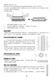
... +12V 5VSB PWR OK GND +5V GND +5V GND +3.3V +3.3V GND +5V +5V +5V Res GND GND GND PS-ON# GND -12V +3.3V 1 13 ATX 12V JPW1 12V 此 12V CPU 供電。 12V FDD1 1 FDD1,支援 360K, 720K, 1.2M, 1.44M 和 2.88M 42 31 GND GND... DMA 66/100/133 4 CD-ROM、120MB IDE1 介面。IDE1 1 個 Master 1 個 Slave 70 DDR DIMM 2. 將 DDR DDR 3. http://www.msi.com.tw/program/products/mainboard/mbd/pro_mbd_trp_list.php DDR 記憶體 Volt Notch 1.
... +12V 5VSB PWR OK GND +5V GND +5V GND +3.3V +3.3V GND +5V +5V +5V Res GND GND GND PS-ON# GND -12V +3.3V 1 13 ATX 12V JPW1 12V 此 12V CPU 供電。 12V FDD1 1 FDD1,支援 360K, 720K, 1.2M, 1.44M 和 2.88M 42 31 GND GND... DMA 66/100/133 4 CD-ROM、120MB IDE1 介面。IDE1 1 個 Master 1 個 Slave 70 DDR DIMM 2. 將 DDR DDR 3. http://www.msi.com.tw/program/products/mainboard/mbd/pro_mbd_trp_list.php DDR 記憶體 Volt Notch 1.
User Guide
Page 77
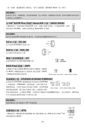
Slave 由 VIA® 8237R Plus 控制的 Serial ATA 介面:SATA1/SATA2 2 Serial ATA Serial ATA 150 MB/s Serial ATA1.0 規格。 serial ATA 90 CD In 介面:CD_IN1 R CD-ROM GND L AUX In 介面:AUX_IN1 aux-in 介面。 JC1 2 L GND R 2 GND 1 CINTRO BIOS Flash 跳線:JWP1 BIOS BIOS BIOS 2 2 1 1 BIOS Flash Unlocked BIOS Flash Locked CPUFAN1/SYSFAN1/PWRFAN1 此 4-pin 的 CPUFAN1 3-pin 的 SYSFAN1 PWRFAN1 12V 3-...
Slave 由 VIA® 8237R Plus 控制的 Serial ATA 介面:SATA1/SATA2 2 Serial ATA Serial ATA 150 MB/s Serial ATA1.0 規格。 serial ATA 90 CD In 介面:CD_IN1 R CD-ROM GND L AUX In 介面:AUX_IN1 aux-in 介面。 JC1 2 L GND R 2 GND 1 CINTRO BIOS Flash 跳線:JWP1 BIOS BIOS BIOS 2 2 1 1 BIOS Flash Unlocked BIOS Flash Locked CPUFAN1/SYSFAN1/PWRFAN1 此 4-pin 的 CPUFAN1 3-pin 的 SYSFAN1 PWRFAN1 12V 3-...
