User Guide
Page 2
...the following help resources for FAQ, technical guide, BIOS updates, driver updates, and other countries. Visit the MSI website for further guidance. Copyright Notice The material in this document, but no solution can be obtained from the user's manual, please contact your system and no ...International Business Machines Corporation. Award® is given as to make changes without notice. Intel® and Pentium® are the properties of Intel Corporation. Revision History Revision V1.0 Revision History First release for P35 Date June 2007 Technical Support If a problem...
...the following help resources for FAQ, technical guide, BIOS updates, driver updates, and other countries. Visit the MSI website for further guidance. Copyright Notice The material in this document, but no solution can be obtained from the user's manual, please contact your system and no ...International Business Machines Corporation. Award® is given as to make changes without notice. Intel® and Pentium® are the properties of Intel Corporation. Revision History Revision V1.0 Revision History First release for P35 Date June 2007 Technical Support If a problem...
User Guide
Page 8
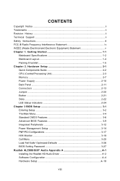
... Mainboard Layout 1-4 Packing Checklist 1-5 Chapter 2. Hardware Setup 2-1 Quick Components Guide 2-2 CPU (Central Processing Unit 2-3 Memory ...2-7 Power Supply ...2-10 Back Panel ...2-11 Connectors ...2-13 Jumper ...2-20 Button ...2-21 Slots ...2-22 LED Status Indicators 2-24 Chapter 3 BIOS Setup 3-1 Entering Setup ...3-2 The Main Menu ...3-4 Standard CMOS Features 3-6 Advanced BIOS Features 3-9 Integrated Peripherals 3-12 Power Management Setup 3-14 PNP/PCI Configurations 3-17 H/W Monitor ...3-19 Cell Menu ...3-20 Load Fail-Safe/ Optimized Defaults 3-26 BIOS Setting Password...
... Mainboard Layout 1-4 Packing Checklist 1-5 Chapter 2. Hardware Setup 2-1 Quick Components Guide 2-2 CPU (Central Processing Unit 2-3 Memory ...2-7 Power Supply ...2-10 Back Panel ...2-11 Connectors ...2-13 Jumper ...2-20 Button ...2-21 Slots ...2-22 LED Status Indicators 2-24 Chapter 3 BIOS Setup 3-1 Entering Setup ...3-2 The Main Menu ...3-4 Standard CMOS Features 3-6 Advanced BIOS Features 3-9 Integrated Peripherals 3-12 Power Management Setup 3-14 PNP/PCI Configurations 3-17 H/W Monitor ...3-19 Cell Menu ...3-20 Load Fail-Safe/ Optimized Defaults 3-26 BIOS Setting Password...
User Guide
Page 10
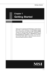
Designed to fit the advanced Intel® Core 2 Quad/Core 2 Duo/ Pentium/Celeron LGA775 processor, the P35 Platinum Combo Series deliver a high performance and professional desktop platform solution. 1-1 Getting Started Chapter 1 Getting Started Thank you for optimal system efficiency. The P35 Platinum Combo Series mainboards are based on Intel® P35 & ICH9R chipsets for choosing the P35 Platinum Combo Series (MS-7338 v1.X) ATX mainboard.
Designed to fit the advanced Intel® Core 2 Quad/Core 2 Duo/ Pentium/Celeron LGA775 processor, the P35 Platinum Combo Series deliver a high performance and professional desktop platform solution. 1-1 Getting Started Chapter 1 Getting Started Thank you for optimal system efficiency. The P35 Platinum Combo Series mainboards are based on Intel® P35 & ICH9R chipsets for choosing the P35 Platinum Combo Series (MS-7338 v1.X) ATX mainboard.
User Guide
Page 11
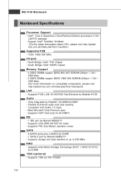
... CPU, please visit http://global. Supports VoIP Card (only for ALC888T) IDE - 1 IDE port by VIA VT6308 1-2 Supports 1394 by Marvell 88SE6111 - t w / index. php?func =c puform ) Supported FSB - 1333/ 1066/ 800 MHz Chipset - Compliant with jack sensing - c om . Supports Intel Martix Storage Technology (AHCI + RAID 0/1/5/10) by Realtek 8111B Audio - p hp?func =t est report ) LAN - Supports PCIE LAN 10/100/1000 Fast Ethernet by ICH9R 1394 (optional) - m si. t w / index. Flexible 8-channel audio...
... CPU, please visit http://global. Supports VoIP Card (only for ALC888T) IDE - 1 IDE port by VIA VT6308 1-2 Supports 1394 by Marvell 88SE6111 - t w / index. php?func =c puform ) Supported FSB - 1333/ 1066/ 800 MHz Chipset - Compliant with jack sensing - c om . Supports Intel Martix Storage Technology (AHCI + RAID 0/1/5/10) by Realtek 8111B Audio - p hp?func =t est report ) LAN - Supports PCIE LAN 10/100/1000 Fast Ethernet by ICH9R 1394 (optional) - m si. t w / index. Flexible 8-channel audio...

User Guide
Page 12
...88MB Connectors Back panel - 1 PS/2 mouse port - 1 PS/2 keyboard port - 2 eSATA ports (support Command Based Port Multipliers) - 6 USB 2.0 Ports - 1 LAN jack (10/100/1000) - 6 flexible audio jacks - 1 1394 port (optional) - 1 Optical S/PDIF-Out (optional) On-Board Pinheaders / Connectors - 3 USB 2.0 pinheaders - 1 1394 pinheader (optional) - 1 chasis intrusion connector - 1 SPDIF-out pinheader - 1 CD-in connector - 2 H/W OC pinheaders (optional) - 1 front audio pinheader - 1 serial pinheader Slots - 1 PCI Express x16 slot - 2 PCI Express x1 slots - 1 PCI Express x4 slot - 2 PCI slots - ATX (30...
...88MB Connectors Back panel - 1 PS/2 mouse port - 1 PS/2 keyboard port - 2 eSATA ports (support Command Based Port Multipliers) - 6 USB 2.0 Ports - 1 LAN jack (10/100/1000) - 6 flexible audio jacks - 1 1394 port (optional) - 1 Optical S/PDIF-Out (optional) On-Board Pinheaders / Connectors - 3 USB 2.0 pinheaders - 1 1394 pinheader (optional) - 1 chasis intrusion connector - 1 SPDIF-out pinheader - 1 CD-in connector - 2 H/W OC pinheaders (optional) - 1 front audio pinheader - 1 serial pinheader Slots - 1 PCI Express x16 slot - 2 PCI Express x1 slots - 1 PCI Express x4 slot - 2 PCI slots - ATX (30...
User Guide
Page 13
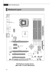
... PCI_E1 P CI _E 2 Intel P35 JPWR3 SYSFAN5 SATA5 SATA1 DIMM_DDR3_2 DIMM_DDR2_4 DIMM_DDR3_1 DIMM_DDR2_3 DIMM_DDR2_2 DIMM_DDR2_1 SATA2 IC IHn9tRel JB1 J B2 (optional ) I/O Chip JCOM1 Codec P CI _E 3 PCI_E4 PCI 1 PCI 2 JAUD1 JCD1 JSLIC1(ALC88 8T) JSP1 JCI1 SATA6 B AT T + IDE1 SATA7 SW1 JU SB3 JUSB2 JUSB1 SYSFAN2 FDD1 J1394_1(option al) SYSFAN3 JFP2 JFP1 P35 Platinum Combo Series (MS-7338 v1.X) ATX Mainboard 1-4
... PCI_E1 P CI _E 2 Intel P35 JPWR3 SYSFAN5 SATA5 SATA1 DIMM_DDR3_2 DIMM_DDR2_4 DIMM_DDR3_1 DIMM_DDR2_3 DIMM_DDR2_2 DIMM_DDR2_1 SATA2 IC IHn9tRel JB1 J B2 (optional ) I/O Chip JCOM1 Codec P CI _E 3 PCI_E4 PCI 1 PCI 2 JAUD1 JCD1 JSLIC1(ALC88 8T) JSP1 JCI1 SATA6 B AT T + IDE1 SATA7 SW1 JU SB3 JUSB2 JUSB1 SYSFAN2 FDD1 J1394_1(option al) SYSFAN3 JFP2 JFP1 P35 Platinum Combo Series (MS-7338 v1.X) ATX Mainboard 1-4

User Guide
Page 21
... the D IMM_D DR 3_1 and DIMM_DDR3_2 DIMM_DDR3_2 slots) 2 DIMM_DDR2_1 D u a l c h a n n e l m o d e DIMM_DDR2_2 population rule for installing memory modules. Enabling Dual-Channel mode can transmit and receive data with DDR2 and the DDR3 standard is not backward compatible, you install DDR2 & DDR3 memory modules simultaneously. Hardware Setup Memory These DIMM slots are used for DDR2 DIMM_DDR3_1 (Install two D DR2/D DR 3 DIMM_DDR2_3 Turbo Cards in DIMM_DDR2_4 the D IMM_D DR 3_1...
... the D IMM_D DR 3_1 and DIMM_DDR3_2 DIMM_DDR3_2 slots) 2 DIMM_DDR2_1 D u a l c h a n n e l m o d e DIMM_DDR2_2 population rule for installing memory modules. Enabling Dual-Channel mode can transmit and receive data with DDR2 and the DDR3 standard is not backward compatible, you install DDR2 & DDR3 memory modules simultaneously. Hardware Setup Memory These DIMM slots are used for DDR2 DIMM_DDR3_1 (Install two D DR2/D DR 3 DIMM_DDR2_3 Turbo Cards in DIMM_DDR2_4 the D IMM_D DR 3_1...
User Guide
Page 27
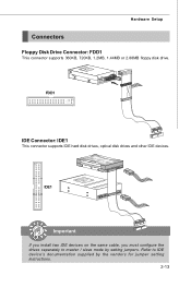
Hardware Setup Connectors Floppy Disk Drive Connector: FDD1 This connector supports 360KB, 720KB, 1.2MB, 1.44MB or 2.88MB floppy disk drive. IDE1 Important If you install two IDE devices on the same cable, you must configure the drives separately to IDE device's documentation supplied by setting jumpers. Refer to master / slave mode by the vendors for jumper setting instructions. 2-13 FDD1 IDE Connector: IDE1 This connector supports IDE hard disk drives, optical disk drives and other IDE devices.
Hardware Setup Connectors Floppy Disk Drive Connector: FDD1 This connector supports 360KB, 720KB, 1.2MB, 1.44MB or 2.88MB floppy disk drive. IDE1 Important If you install two IDE devices on the same cable, you must configure the drives separately to IDE device's documentation supplied by setting jumpers. Refer to master / slave mode by the vendors for jumper setting instructions. 2-13 FDD1 IDE Connector: IDE1 This connector supports IDE hard disk drives, optical disk drives and other IDE devices.
User Guide
Page 29
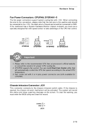
... BIOS utility and clear the record. Chassis Intrusion Connector: JCI1 This connector connects to the recommended CPU fans at processor's official website or consult the vendors for CPUFAN. Hardware Setup Fan Power Connectors: CPUFAN, SYSFAN1~5 The fan power connectors support system cooling fan with 3 or 4 pins power connector are both available for proper CPU cooling fan. 2. the black wire is the positive and should be connected to take advantage of the CPU fan control. If the mainboard has a System Hardware Monitor chipset...
... BIOS utility and clear the record. Chassis Intrusion Connector: JCI1 This connector connects to the recommended CPU fans at processor's official website or consult the vendors for CPUFAN. Hardware Setup Fan Power Connectors: CPUFAN, SYSFAN1~5 The fan power connectors support system cooling fan with 3 or 4 pins power connector are both available for proper CPU cooling fan. 2. the black wire is the positive and should be connected to take advantage of the CPU fan control. If the mainboard has a System Hardware Monitor chipset...

User Guide
Page 37
... typically connected to configure any necessary hardware or software settings for the expansion card, such as follows: PCI Slot 1 PCI Slot 2 Order 1 INT A# INT B# Order 2 INT B# INT C# Order 3 INT C# INT D# Order 4 INT D# INT A# 2-23 Meanwhile, read the documentation for the expansion card to the PCI bus pins as jumpers, switches or BIOS configuration. Hardware Setup PCI (Peripheral Component Interconnect) Slot The PCI slot supports LAN card, SCSI card, USB card, and other add-on cards that comply with PCI specifications. 32-bit PCI Slot...
... typically connected to configure any necessary hardware or software settings for the expansion card, such as follows: PCI Slot 1 PCI Slot 2 Order 1 INT A# INT B# Order 2 INT B# INT C# Order 3 INT C# INT D# Order 4 INT D# INT A# 2-23 Meanwhile, read the documentation for the expansion card to the PCI bus pins as jumpers, switches or BIOS configuration. Hardware Setup PCI (Peripheral Component Interconnect) Slot The PCI slot supports LAN card, SCSI card, USB card, and other add-on cards that comply with PCI specifications. 32-bit PCI Slot...
User Guide
Page 46
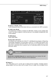
... a utility that you to a safe place before the hard disk becomes offline. Hard Disk S.M.A.R.T. Floppy A This item allows you connected to the SATA connector. Available options: [None], [360K, 5.25 in.], [1.2M, 5.25 in.], [720K, 3.5 in.], [1.44M, 3.5 in.], [2.88M, 3.5 in.]. 3-7 Important Serial-ATA 1/2/3/4/5/6 Channel are appearing when you to the IDE/ SATA connector on the mainboard. LBA/Large M ode This allows you connect the HD devices to enable or disable the LBA Mode.
... a utility that you to a safe place before the hard disk becomes offline. Hard Disk S.M.A.R.T. Floppy A This item allows you connected to the SATA connector. Available options: [None], [360K, 5.25 in.], [1.2M, 5.25 in.], [720K, 3.5 in.], [1.44M, 3.5 in.], [2.88M, 3.5 in.]. 3-7 Important Serial-ATA 1/2/3/4/5/6 Channel are appearing when you to the IDE/ SATA connector on the mainboard. LBA/Large M ode This allows you connect the HD devices to enable or disable the LBA Mode.
User Guide
Page 51
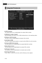
... to use a USB-interfaced device in the operating system. USB Device Legacy Support Select [Enabled] if you need to enable/disable the onboard IEEE1394 controller. MS-7338 Mainboard Integrated Peripherals USB Controller This setting allows you to enable/disable the onboard IDE controller. Extra IDE Controller This item allows you to enable/disable the onboard USB controller. On-Chip ATA Devices Press to invoke the Boot ROM of the LAN controller. LAN Option ROM This item is used to decide whether to enter the sub-menu and the following screen appears...
... to use a USB-interfaced device in the operating system. USB Device Legacy Support Select [Enabled] if you need to enable/disable the onboard IEEE1394 controller. MS-7338 Mainboard Integrated Peripherals USB Controller This setting allows you to enable/disable the onboard IDE controller. Extra IDE Controller This item allows you to enable/disable the onboard USB controller. On-Chip ATA Devices Press to invoke the Boot ROM of the LAN controller. LAN Option ROM This item is used to decide whether to enter the sub-menu and the following screen appears...
User Guide
Page 52
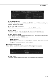
Oc-Chip SATA Controller These items allow users to select the type of IDE devices. AHCI Port0~5 Press to enable or disable the SATA controller. I/O Device Configuration Press to IDE drives. BIOS Setup PCI IDE BusMaster This item allows you to enable/ disable BIOS to used to enter the AHCI settings sub-menu. AHCI Devices Group Press to enable/disable the RAID function for the first serial port. 3-13 RAID Mode This item is used PCI busmastering for reading/ writing to enter the sub-menu and the following screen appears: COM Port 1 Select an...
Oc-Chip SATA Controller These items allow users to select the type of IDE devices. AHCI Port0~5 Press to enable or disable the SATA controller. I/O Device Configuration Press to IDE drives. BIOS Setup PCI IDE BusMaster This item allows you to enable/ disable BIOS to used to enter the AHCI settings sub-menu. AHCI Devices Group Press to enable/disable the RAID function for the first serial port. 3-13 RAID Mode This item is used PCI busmastering for reading/ writing to enter the sub-menu and the following screen appears: COM Port 1 Select an...
User Guide
Page 58
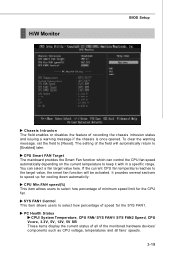
... [Reset]. CPU Smart FAN Target The mainboard provides the Smart Fan function which can select a fan target value here. To clear the warning message, set the field to speed up for the SYS FAN1. PC Health Status CPU/ System Temperature, CPU FAN/ SYS FAN1/ SYS FAN2 Speed, CPU Vcore, 3.3V, 5V, 12V, 5V SB These items display the current status of all of the monitored hardware devices/ components such as CPU voltage, temperatures...
... [Reset]. CPU Smart FAN Target The mainboard provides the Smart Fan function which can select a fan target value here. To clear the warning message, set the field to speed up for the SYS FAN1. PC Health Status CPU/ System Temperature, CPU FAN/ SYS FAN1/ SYS FAN2 Speed, CPU Vcore, 3.3V, 5V, 12V, 5V SB These items display the current status of all of the monitored hardware devices/ components such as CPU voltage, temperatures...
User Guide
Page 60
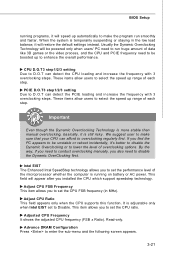
... set to set the CPU FSB frequency (in the low load balance, it is more stable than manual overclocking, basically, it will be boosted up to overclocking regularly first. Adjust CPU Ratio This field appears only when the CPU supports this function. Intel EIST The Enhanced Intel SpeedStep technology allows you also need to be powered only when users' PC need to enter the sub-menu...
... set to set the CPU FSB frequency (in the low load balance, it is more stable than manual overclocking, basically, it will be boosted up to overclocking regularly first. Adjust CPU Ratio This field appears only when the CPU supports this function. Intel EIST The Enhanced Intel SpeedStep technology allows you also need to be powered only when users' PC need to enter the sub-menu...
User Guide
Page 62
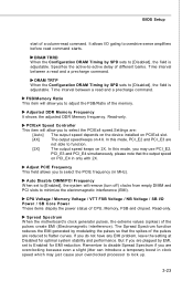
... 2X. Auto Disable DIMM/PCI Frequency W hen set to [Enabled], the system will allow you may just cause your overclocked processor to adjust the FSB/Ratio of a column-read and a precharge command. BIOS Setup start of the memory. In this mode, you to lock up. 3-23 Read-only. Remember to function. [2X] The output speed keeps on 4X. Spread Spectrum W hen the motherboard's clock generator pulses...
... 2X. Auto Disable DIMM/PCI Frequency W hen set to [Enabled], the system will allow you may just cause your overclocked processor to adjust the FSB/Ratio of a column-read and a precharge command. BIOS Setup start of the memory. In this mode, you to lock up. 3-23 Read-only. Remember to function. [2X] The output speed keeps on 4X. Spread Spectrum W hen the motherboard's clock generator pulses...

User Guide
Page 68
...-ROM drive. Click here Important The HD Audio Configuration software utility is under continuous update to 2-, 4-, 6-, 8- Hence, the program screens shown here in different operating systems. 1. For Windows® XP, you must install W indows® XP Service Pack1 or later before installing the driver. Follow the procedures described below to install the drivers for different operating systems. Installation for reference only. a A-2 MS-7338 Mainboard Installing the Realtek HD Audio Driver...
...-ROM drive. Click here Important The HD Audio Configuration software utility is under continuous update to 2-, 4-, 6-, 8- Hence, the program screens shown here in different operating systems. 1. For Windows® XP, you must install W indows® XP Service Pack1 or later before installing the driver. Follow the procedures described below to install the drivers for different operating systems. Installation for reference only. a A-2 MS-7338 Mainboard Installing the Realtek HD Audio Driver...

User Guide
Page 91
... be available. MB Click MB button to read current CPU temperature, FSB and CPU clock of graphics card will show below . VGA Click VGA button to read current GPU temperature, GPU clock and memory clock of mainboard will show below . DOT Click DOT button to execute the function. Dual Core Center Main Before using this utility. Introduction: Click each button appearing above to enter sub-menu to make further configuration or to enable or disable the Dynamic Overclocking Technology. B-3
... be available. MB Click MB button to read current CPU temperature, FSB and CPU clock of graphics card will show below . VGA Click VGA button to read current GPU temperature, GPU clock and memory clock of mainboard will show below . DOT Click DOT button to execute the function. Dual Core Center Main Before using this utility. Introduction: Click each button appearing above to enter sub-menu to make further configuration or to enable or disable the Dynamic Overclocking Technology. B-3
User Guide
Page 102
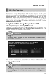
... reset RAID volumes. The Intel Matrix Stroage Manager Option ROM is only available with a supported Intel chipset. After the above message shows, press and keys simultaneously to enter the "Intel(R) RAID for a few seconds: Important The "Driver Model", "Serial #" and "Size" in system boot-up, during the POST (Power-On Self Test). Creating, Deleting and Resetting RAID Volumes: The Serial ATA RAID volume may be configured using the RAID Configuration utility stored within the Intel RAID Option ROM...
... reset RAID volumes. The Intel Matrix Stroage Manager Option ROM is only available with a supported Intel chipset. After the above message shows, press and keys simultaneously to enter the "Intel(R) RAID for a few seconds: Important The "Driver Model", "Serial #" and "Size" in system boot-up, during the POST (Power-On Self Test). Creating, Deleting and Resetting RAID Volumes: The Serial ATA RAID volume may be configured using the RAID Configuration utility stored within the Intel RAID Option ROM...
User Guide
Page 108
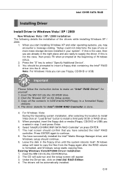
... SATA RAID Controller" an press ENTER. 7. Press ENTER again to supply the driver. If this is not the case, then press F6 when prompted at the beginning of W indows setup. 2. W hen you start installing Windows XP and older operating systems, you created in Windows Vista / XP / 2000 † New Windows Vista / XP / 2000 Installation The following details the installation of one or more mass storage devices installed in the floppy drive...
... SATA RAID Controller" an press ENTER. 7. Press ENTER again to supply the driver. If this is not the case, then press F6 when prompted at the beginning of W indows setup. 2. W hen you start installing Windows XP and older operating systems, you created in Windows Vista / XP / 2000 † New Windows Vista / XP / 2000 Installation The following details the installation of one or more mass storage devices installed in the floppy drive...

