User Guide
Page 1
... cables and A.C. If this equipment does cause harmful interference to radio or television reception, which can radiate radio frequency energy and, if not installed and used in accordance with the limits for a class B digital device, pursuant to part 15 of the measures listed below. n Increase the separation between the equipment and receiver. Micro-Star International MS-7529 G52-75291X1 n Connect...
... cables and A.C. If this equipment does cause harmful interference to radio or television reception, which can radiate radio frequency energy and, if not installed and used in accordance with the limits for a class B digital device, pursuant to part 15 of the measures listed below. n Increase the separation between the equipment and receiver. Micro-Star International MS-7529 G52-75291X1 n Connect...
User Guide
Page 3
... safety instructions carefully. The power cord or plug is incorrectly replaced. n The openings on a reliable flat surface before connecting the equipment to moisture. - n Lay this User Manual for air convection hence protects the equipment from humidity. n All cautions and warnings on the equipment should be noted. The equipment does not work well or you can not step on card...
... safety instructions carefully. The power cord or plug is incorrectly replaced. n The openings on a reliable flat surface before connecting the equipment to moisture. - n Lay this User Manual for air convection hence protects the equipment from humidity. n All cautions and warnings on the equipment should be noted. The equipment does not work well or you can not step on card...
User Guide
Page 7
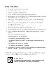
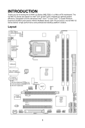
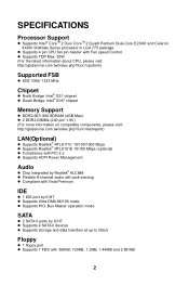
Layout 1 Designed to fit the advanced Intel® CoreTM 2 Duo/ CoreTM 2 Quad/ Pentium Dual-Core E2XXX and Celeron 4XXX/ Wolfdale Series LGA 775 processor, the G31M3 V2 Series deliver a high performance and professional desktop platform solution. INTRODUCTION Thank you for optimal system efficiency. The G31M3 V2 Series are based on Intel® G31 & Intel® ICH7 chipsets for choosing the G31M3 V2 Series (MS-7529 v1.x) Micro-ATX mainboard.
Layout 1 Designed to fit the advanced Intel® CoreTM 2 Duo/ CoreTM 2 Quad/ Pentium Dual-Core E2XXX and Celeron 4XXX/ Wolfdale Series LGA 775 processor, the G31M3 V2 Series deliver a high performance and professional desktop platform solution. INTRODUCTION Thank you for optimal system efficiency. The G31M3 V2 Series are based on Intel® G31 & Intel® ICH7 chipsets for choosing the G31M3 V2 Series (MS-7529 v1.x) Micro-ATX mainboard.
User Guide
Page 8
...) LAN(Optional) l Supports Realtek® RTL8111C 10/100/1000 Mbps l Supports Realtek® RTL8101E 10/100 Mbps (optional) l Compliance with PCI 2.2 l Supports ACPI Power Management Audio l Chip integrated by Realtek® ALC888 l Flexible 8-channel audio with jack sensing l Compliant with Vista Premium IDE l 1 IDE port by ICH7 l Supports Ultra DMA 66/100 mode l Supports PIO, Bus Master operation mode SATA l 2 SATA II ports by ICH7 l Supports 4 SATA II devices l Supports storage and data transfers at up to 3Gb/s Floppy l 1 floppy port l Supports 1 FDD...
...) LAN(Optional) l Supports Realtek® RTL8111C 10/100/1000 Mbps l Supports Realtek® RTL8101E 10/100 Mbps (optional) l Compliance with PCI 2.2 l Supports ACPI Power Management Audio l Chip integrated by Realtek® ALC888 l Flexible 8-channel audio with jack sensing l Compliant with Vista Premium IDE l 1 IDE port by ICH7 l Supports Ultra DMA 66/100 mode l Supports PIO, Bus Master operation mode SATA l 2 SATA II ports by ICH7 l Supports 4 SATA II devices l Supports storage and data transfers at up to 3Gb/s Floppy l 1 floppy port l Supports 1 FDD...
User Guide
Page 9
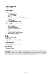
... Supports TPM Connectors l Back panel - 1 PS/2 mouse port - 1 PS/2 keyboard port - 1 serial port (COM1) - 1 VGA port - 1 parallel port supporting SPP/EPP/ECP mode - 4 USB 2.0 Ports - 1 RJ-45 LAN jack - 3/6 flexible audio jacks(optional) l On-Board Pinheaders / Connectors - 2 USB 2.0 pinheaders - 1 CD-In connector - 1 S/PDIF-Out pinheader - 1 Front Panel Audio pinheader - 1 serial port connector - 1 TPM connector (optional) - 1 chassis intrusion switch pinheader - 1 SPI Debugging connector Slots l 1 PCI Express x16 slot l 2 PCI slots l Support 3.3V / 5V PCI bus Interface Form Factor l Micro-ATX...
... Supports TPM Connectors l Back panel - 1 PS/2 mouse port - 1 PS/2 keyboard port - 1 serial port (COM1) - 1 VGA port - 1 parallel port supporting SPP/EPP/ECP mode - 4 USB 2.0 Ports - 1 RJ-45 LAN jack - 3/6 flexible audio jacks(optional) l On-Board Pinheaders / Connectors - 2 USB 2.0 pinheaders - 1 CD-In connector - 1 S/PDIF-Out pinheader - 1 Front Panel Audio pinheader - 1 serial port connector - 1 TPM connector (optional) - 1 chassis intrusion switch pinheader - 1 SPI Debugging connector Slots l 1 PCI Express x16 slot l 2 PCI slots l Support 3.3V / 5V PCI bus Interface Form Factor l Micro-ATX...
User Guide
Page 10
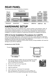
... side. 3. The surface of your CPU & mainboard. Open the load lever. 5. It also provides the instructions on connecting the peripheral devices, such as how to setup the jumpers on CPU before installing the heat sink/cooler fan for correct mating, put down the CPU in holding the components and follow the installation procedures. Remove the cap from damage. Wrong installation will cause the damage of...
... side. 3. The surface of your CPU & mainboard. Open the load lever. 5. It also provides the instructions on connecting the peripheral devices, such as how to setup the jumpers on CPU before installing the heat sink/cooler fan for correct mating, put down the CPU in holding the components and follow the installation procedures. Remove the cap from damage. Wrong installation will cause the damage of...
User Guide
Page 11
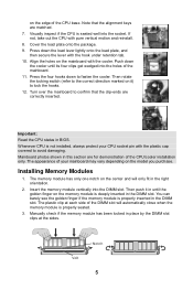
... installed, always protect your mainboard may vary depending on the model you purchase. You can barely see the golden finger if the memory module is seated well into the socket. Push down to confirm that the alignment keys are correctly inserted. Important: Read the CPU status in the DIMM slot. Visually inspect if the CPU is properly inserted in BIOS. Installing Memory...
... installed, always protect your mainboard may vary depending on the model you purchase. You can barely see the golden finger if the memory module is seated well into the socket. Push down to confirm that the alignment keys are correctly inserted. Important: Read the CPU status in the DIMM slot. Visually inspect if the CPU is properly inserted in BIOS. Installing Memory...
User Guide
Page 12
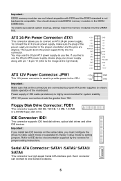
... you install two IDE devices on the same cable, you like . Each connector can connect to connect an ATX 24-pin power supply. IDE Connector: IDE1 This connector supports IDE hard disk drives, optical disk drives and other IDE devices. To connect the ATX 24-pin power supply, make sure the plug of 350 watts (and above) is highly recommended for jumper setting instructions. If you must configure the drives to cable select mode or separately to master / slave mode by the vendors for system stability. Floppy Disk Drive Connector: FDD1 This connector supports...
... you install two IDE devices on the same cable, you like . Each connector can connect to connect an ATX 24-pin power supply. IDE Connector: IDE1 This connector supports IDE hard disk drives, optical disk drives and other IDE devices. To connect the ATX 24-pin power supply, make sure the plug of 350 watts (and above) is highly recommended for jumper setting instructions. If you must configure the drives to cable select mode or separately to master / slave mode by the vendors for system stability. Floppy Disk Drive Connector: FDD1 This connector supports...
User Guide
Page 13
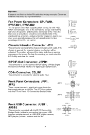
... -board, you must use a specially designed fan with Intel® I /O Connectivity Design Guide. L GND R JFP2 87 Speaker Power LED 21 JFP1 12 + -- + -+ HDD LED Power LED Reset Switch Power Switch 9 10 USB1+ USB1- Fan Power Connectors: CPUFAN1, SYSFAN1, SYSFAN2 The fan power connectors support system cooling fan with Intel® Front Panel I /O Connectivity Design Guide, is ideal for electrical connection to connect S/PDIF (Sony & Philips Digital Interconnect Format) interface for external audio input. To clear the warning, you must enter the BIOS utility and clear...
... -board, you must use a specially designed fan with Intel® I /O Connectivity Design Guide. L GND R JFP2 87 Speaker Power LED 21 JFP1 12 + -- + -+ HDD LED Power LED Reset Switch Power Switch 9 10 USB1+ USB1- Fan Power Connectors: CPUFAN1, SYSFAN1, SYSFAN2 The fan power connectors support system cooling fan with Intel® Front Panel I /O Connectivity Design Guide, is ideal for electrical connection to connect S/PDIF (Sony & Philips Digital Interconnect Format) interface for external audio input. To clear the warning, you must enter the BIOS utility and clear...
User Guide
Page 14
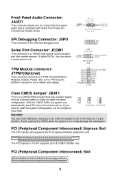
... platform manual for internal debugging only. With the CMOS RAM, the system can clear CMOS by shorting 2-3 pin while the system is turned on ; Avoid clearing the CMOS while the system is for more details and usages. PCI (Peripheral Component Interconnect) Express Slot The PCI Express slot supports the PCI Express interface expansion card. it . TPM Module connector: JTPM1(Optional) This connector connects to 4.0 GB/s transfer rate. DSR DTR CTS (2) SIN (1) DC D Key,no pin (10) R I /O Connectivity Design Guide...
... platform manual for internal debugging only. With the CMOS RAM, the system can clear CMOS by shorting 2-3 pin while the system is turned on ; Avoid clearing the CMOS while the system is for more details and usages. PCI (Peripheral Component Interconnect) Express Slot The PCI Express slot supports the PCI Express interface expansion card. it . TPM Module connector: JTPM1(Optional) This connector connects to 4.0 GB/s transfer rate. DSR DTR CTS (2) SIN (1) DC D Key,no pin (10) R I /O Connectivity Design Guide...
User Guide
Page 15
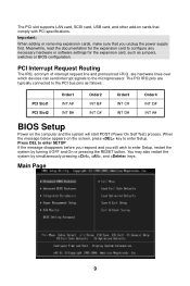
... or pressing the RESET button. PCI Interrupt Request Routing The IRQ, acronym of interrupt request line and pronounced I-R-Q, are typically connected to enter Setup, restart the system by simultaneously pressing , , and keys. Important: When adding or removing expansion cards, make sure that comply with PCI specifications. Main Page 9 The PCI slot supports LAN card, SCSI card, USB card, and other add-on cards that you still wish to the PCI bus pins as jumpers, switches or BIOS configuration.
... or pressing the RESET button. PCI Interrupt Request Routing The IRQ, acronym of interrupt request line and pronounced I-R-Q, are typically connected to enter Setup, restart the system by simultaneously pressing , , and keys. Important: When adding or removing expansion cards, make sure that comply with PCI specifications. Main Page 9 The PCI slot supports LAN card, SCSI card, USB card, and other add-on cards that you still wish to the PCI bus pins as jumpers, switches or BIOS configuration.
User Guide
Page 16
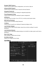
... your settings for frequency/voltage control. H/W Monitor This entry shows the status of special enhanced features. Load Optimized Defaults Use this menu to load the BIOS default values that are factory settings for system operations. Save & Exit Setup Save changes to setup the items of your CPU, fan, warning overall system status. Load Fail-Safe Defaults Use this menu to load factory default settings into the BIOS for stable system performance operations. Cell Menu 10 Power Management Setup Use this menu for...
... your settings for frequency/voltage control. H/W Monitor This entry shows the status of special enhanced features. Load Optimized Defaults Use this menu to load the BIOS default values that are factory settings for system operations. Save & Exit Setup Save changes to setup the items of your CPU, fan, warning overall system status. Load Fail-Safe Defaults Use this menu to load factory default settings into the BIOS for stable system performance operations. Cell Menu 10 Power Management Setup Use this menu for...
User Guide
Page 17
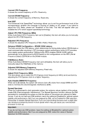
... performance. This field will remove (turn off) clocks from empty DIMM and PCI slots to adjust the CPU Ratio, please set the performance level of the memory. Read-only. Advance DRAM Configuration > DRAM CAS# Latency The field controls the CAS latency, which support speedstep technology. Adjust PCI-E Frequency (MHz) This item allows you to select the PCI Express clock frequency (in clock speed which may just cause your overclocked processor to [Enabled], the system will...
... performance. This field will remove (turn off) clocks from empty DIMM and PCI slots to adjust the CPU Ratio, please set the performance level of the memory. Read-only. Advance DRAM Configuration > DRAM CAS# Latency The field controls the CAS latency, which support speedstep technology. Adjust PCI-E Frequency (MHz) This item allows you to select the PCI Express clock frequency (in clock speed which may just cause your overclocked processor to [Enabled], the system will...
User Guide
Page 18
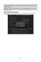
For the most suitable Spread Spectrum value, please consult your overclocked processor to disable Spread Spectrum if you are overclocking because even a slight jitter can load the default values provided by the mainboard manufacturer for the stable performance. 12 Load Optimized Defaults You can introduce a temporary boost in clock speed which may just cause your local EMI regulation. Remember to lock up. The greater the Spread Spectrum value is, the greater the EMI is reduced, and the system will become less stable.
For the most suitable Spread Spectrum value, please consult your overclocked processor to disable Spread Spectrum if you are overclocking because even a slight jitter can load the default values provided by the mainboard manufacturer for the stable performance. 12 Load Optimized Defaults You can introduce a temporary boost in clock speed which may just cause your local EMI regulation. Remember to lock up. The greater the Spread Spectrum value is, the greater the EMI is reduced, and the system will become less stable.
User Guide
Page 65
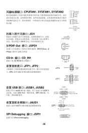
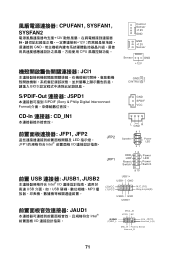
... internal debugging. 59 CPUFAN1, SYSFAN1, SYSFAN2 12V 12V Control Sensor +12V GND GND +12V Sensor JCI1 BIOS S/PDIF-Out 接口: JSPD1 SPDIF(Sony & Philips Sensor GND +12V GND 2 CINTRU 1 GND SPDIF VCC CD-In 接口: CD_IN1 CD-ROM JFP1, JFP2 JFP2 是和 Intel 的 I/O L GND R 87 JFP2 JFP1 Speaker Power LED 21 12 + -- + -+ HDD LED Power LED Reset Switch Power Switch 9 10 前置 USB...
... internal debugging. 59 CPUFAN1, SYSFAN1, SYSFAN2 12V 12V Control Sensor +12V GND GND +12V Sensor JCI1 BIOS S/PDIF-Out 接口: JSPD1 SPDIF(Sony & Philips Sensor GND +12V GND 2 CINTRU 1 GND SPDIF VCC CD-In 接口: CD_IN1 CD-ROM JFP1, JFP2 JFP2 是和 Intel 的 I/O L GND R 87 JFP2 JFP1 Speaker Power LED 21 12 + -- + -+ HDD LED Power LED Reset Switch Power Switch 9 10 前置 USB...
User Guide
Page 68
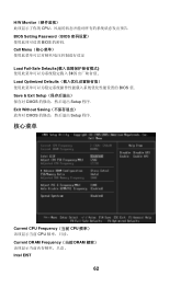
Save & Exit Setup CMOS Setup 程序. H/W Monitor CPU BIOS Setting Password(BIOS BIOS 的密码. Exit Without Saving CMOS Setup 程序. 核心菜单 Current CPU Frequency(当前 CPU CPU Current DRAM Frequency(当前 DRAM Intel EIST 62 Cell Menu Load Fail-Safe Defaults BIOS Load Optimized Defaults BIOS 值.
Save & Exit Setup CMOS Setup 程序. H/W Monitor CPU BIOS Setting Password(BIOS BIOS 的密码. Exit Without Saving CMOS Setup 程序. 核心菜单 Current CPU Frequency(当前 CPU CPU Current DRAM Frequency(当前 DRAM Intel EIST 62 Cell Menu Load Fail-Safe Defaults BIOS Load Optimized Defaults BIOS 值.
User Guide
Page 77
GND USB0+ JAUD1 Intel I /O USB USB MP3 L GND R JFP2 87 Speaker Power LED 21 JFP1 12 + -- + -+ HDD LED Power LED Reset Switch Power Switch 9 10 USB1+ USB1- GND (2)VCC (1 )VC C N.C.(10) Key,no pin(9) USB0- CPUFAN1, SYSFAN1, SYSFAN2 12V 12V GND CPU JCI1 BIOS Control Sensor +12V GND GND +12V Sensor Sensor GND +12V GND 2 CINTRU 1 S/PDIF-Out 連接器: JSPD1 S/PDIF (Sony & Philip Digital Interconnect Format GND...
GND USB0+ JAUD1 Intel I /O USB USB MP3 L GND R JFP2 87 Speaker Power LED 21 JFP1 12 + -- + -+ HDD LED Power LED Reset Switch Power Switch 9 10 USB1+ USB1- GND (2)VCC (1 )VC C N.C.(10) Key,no pin(9) USB0- CPUFAN1, SYSFAN1, SYSFAN2 12V 12V GND CPU JCI1 BIOS Control Sensor +12V GND GND +12V Sensor Sensor GND +12V GND 2 CINTRU 1 S/PDIF-Out 連接器: JSPD1 S/PDIF (Sony & Philip Digital Interconnect Format GND...
User Guide
Page 80
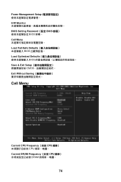
Power Management Setup H/W Monitor BIOS Setting Password(設定 BIOS BIOS 密碼。 Cell Menu Load Fail-Safe Defaults BIOS Load Optimized Defaults BIOS Save & Exit Setup CMOS Exit Without Saving Cell Menu Current CPU Frequency(目前 CPU CPU Current DRAM Frequency(目前 CPU DRAM 74
Power Management Setup H/W Monitor BIOS Setting Password(設定 BIOS BIOS 密碼。 Cell Menu Load Fail-Safe Defaults BIOS Load Optimized Defaults BIOS Save & Exit Setup CMOS Exit Without Saving Cell Menu Current CPU Frequency(目前 CPU CPU Current DRAM Frequency(目前 CPU DRAM 74
User Guide
Page 89
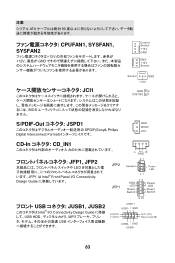
... BIOS Control Sensor +12V GND GND +12V Sensor Sensor GND +12V GND 2 CINTRU 1 S/PDIF-Out JSPD1 SPDIF(Sony& Philips Digital Interconnect Format GND SPDIF VCC CD-In CD_IN1 L GND R JFP1, JFP2 LED JFP1 は Intel® Front Panel I/O Connectivity Design Guide JFP2 JFP1 87 Speaker Power LED 21 12 + -- + -+ HDD LED Power LED Reset Switch Power Switch 9 10 USB JUSB1, JUSB2 Intel® I/O Connectivity Design Guide に準拠 して、USB HDD...
... BIOS Control Sensor +12V GND GND +12V Sensor Sensor GND +12V GND 2 CINTRU 1 S/PDIF-Out JSPD1 SPDIF(Sony& Philips Digital Interconnect Format GND SPDIF VCC CD-In CD_IN1 L GND R JFP1, JFP2 LED JFP1 は Intel® Front Panel I/O Connectivity Design Guide JFP2 JFP1 87 Speaker Power LED 21 12 + -- + -+ HDD LED Power LED Reset Switch Power Switch 9 10 USB JUSB1, JUSB2 Intel® I/O Connectivity Design Guide に準拠 して、USB HDD...
User Guide
Page 92
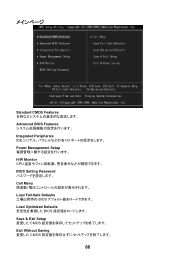
Standard CMOS Features Advanced BIOS Features Integrated Peripherals IDE I/O Power Management Setup H/W Monitor CPU BIOS Setting Password Cell Menu Load Fail-Safe Defaults BIOS Load Optimized Defaults BIOS Save & Exit Setup CMOS Exit Without Saving CMOS 86
Standard CMOS Features Advanced BIOS Features Integrated Peripherals IDE I/O Power Management Setup H/W Monitor CPU BIOS Setting Password Cell Menu Load Fail-Safe Defaults BIOS Load Optimized Defaults BIOS Save & Exit Setup CMOS Exit Without Saving CMOS 86


