User Guide
Page 8
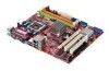
... pin-header with Fan speed Control l Supports TDP Max. 95W (For the latest information about CPU, please visit: http://global.msi.com.tw/index.php?func=cpuform) Supported FSB l 800/ 1066/ 1333 MHz Chipset l North Bridge: Intel® G31 chipset l South Bridge: Intel® ICH7 chipset Memory Support l DDR2 667/ 800 SDRAM (4GB Max) l 2 DDR2...
... pin-header with Fan speed Control l Supports TDP Max. 95W (For the latest information about CPU, please visit: http://global.msi.com.tw/index.php?func=cpuform) Supported FSB l 800/ 1066/ 1333 MHz Chipset l North Bridge: Intel® G31 chipset l South Bridge: Intel® ICH7 chipset Memory Support l DDR2 667/ 800 SDRAM (4GB Max) l 2 DDR2...
User Guide
Page 12
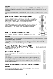
... GND +3.3V +3.3V GND +5V +5V +5V Res GND GND GND PS-ON# GND -12V +3.3V ATX 12V Power Connector: JPW1 +12V GND This 12V power connector is used to provide power to the CPU. +12V GND Important: Make sure that all the connectors are aligned. Then push down the power supply... with DDR and the DDR2 standard is a high-speed Serial ATA interface port. Refer to use the 20-pin ATX power supply as you like. Floppy Disk Drive Connector: FDD1 This connector supports 360 KB, 720 KB, 1.2 MB, 1.44 MB or 2.88 MB floppy disk drive. If you like to IDE device...
... GND +3.3V +3.3V GND +5V +5V +5V Res GND GND GND PS-ON# GND -12V +3.3V ATX 12V Power Connector: JPW1 +12V GND This 12V power connector is used to provide power to the CPU. +12V GND Important: Make sure that all the connectors are aligned. Then push down the power supply... with DDR and the DDR2 standard is a high-speed Serial ATA interface port. Refer to use the 20-pin ATX power supply as you like. Floppy Disk Drive Connector: FDD1 This connector supports 360 KB, 720 KB, 1.2 MB, 1.44 MB or 2.88 MB floppy disk drive. If you like to IDE device...
User Guide
Page 13
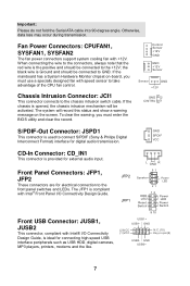
Fan Power Connectors: CPUFAN1, SYSFAN1, SYSFAN2 The fan power connectors support system cooling fan with speed sensor to the chassis intrusion switch cable. If the mainboard has a System Hardware Monitor chipset on the screen. The JFP1 ... the positive and should be connected to the front panel switches and LEDs. Chassis Intrusion Connector: JCI1 This connector connects to take advantage of the CPU fan control. To clear the warning, you must enter the BIOS utility and clear the record. GND SPDIF VCC CD-In Connector: CD_IN1 This connector...
Fan Power Connectors: CPUFAN1, SYSFAN1, SYSFAN2 The fan power connectors support system cooling fan with speed sensor to the chassis intrusion switch cable. If the mainboard has a System Hardware Monitor chipset on the screen. The JFP1 ... the positive and should be connected to the front panel switches and LEDs. Chassis Intrusion Connector: JCI1 This connector connects to take advantage of the CPU fan control. To clear the warning, you must enter the BIOS utility and clear the record. GND SPDIF VCC CD-In Connector: CD_IN1 This connector...
User Guide
Page 17
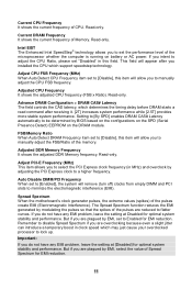
... empty DIMM and PCI slots to be determined by adjusting the PCI Express clock to lock up. Spread Spectrum When the motherboard's clock generator pulses, the extreme values (spikes) of Memory. Auto Disable DIMM/PCI Frequency When set to manually adjust the FSB.../Ratio of CPU. Advance DRAM Configuration > DRAM CAS# Latency The field controls the CAS latency, which support speedstep technology. Adjusted CPU Frequency It shows the adjusted CPU frequency (FSB x Ratio). Important: If you to [Disable], this field...
... empty DIMM and PCI slots to be determined by adjusting the PCI Express clock to lock up. Spread Spectrum When the motherboard's clock generator pulses, the extreme values (spikes) of Memory. Auto Disable DIMM/PCI Frequency When set to manually adjust the FSB.../Ratio of CPU. Advance DRAM Configuration > DRAM CAS# Latency The field controls the CAS latency, which support speedstep technology. Adjusted CPU Frequency It shows the adjusted CPU frequency (FSB x Ratio). Important: If you to [Disable], this field...


