User Guide
Page 8
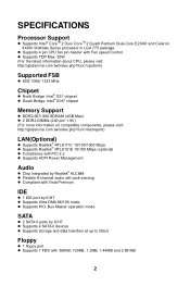
... pin-header with Fan speed Control l Supports TDP Max. 95W (For the latest information about CPU, please visit: http://global.msi.com.tw/index.php?func=cpuform) Supported FSB l 800/ 1066/ 1333 MHz Chipset l North Bridge: Intel® G31 chipset... SDRAM (4GB Max) l 2 DDR2 DIMMs (240 pin/ 1.8V) (For more information on compatible components, please visit: http://global.msi.com.tw/index.php?func=testreport) LAN(Optional) l Supports Realtek® RTL8111C 10/100/1000 Mbps l Supports Realtek® RTL8101E 10...3Gb/s Floppy l 1 floppy port l Supports 1 FDD with 360KB, 720KB, 1.2MB, 1.44MB and 2.88 MB 2
... pin-header with Fan speed Control l Supports TDP Max. 95W (For the latest information about CPU, please visit: http://global.msi.com.tw/index.php?func=cpuform) Supported FSB l 800/ 1066/ 1333 MHz Chipset l North Bridge: Intel® G31 chipset... SDRAM (4GB Max) l 2 DDR2 DIMMs (240 pin/ 1.8V) (For more information on compatible components, please visit: http://global.msi.com.tw/index.php?func=testreport) LAN(Optional) l Supports Realtek® RTL8111C 10/100/1000 Mbps l Supports Realtek® RTL8101E 10...3Gb/s Floppy l 1 floppy port l Supports 1 FDD with 360KB, 720KB, 1.2MB, 1.44MB and 2.88 MB 2
User Guide
Page 12
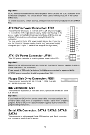
... high-speed Serial ATA interface port. Serial ATA Connector: SATA1 /SATA2/ SATA3/ SATA4 This connector is not backwards compatible. To connect the ATX 24-pin power supply, make sure the plug of the power supply is highly recommended for jumper setting instructions. Then push down the power ...MB or 2.88 MB floppy disk drive. Refer to IDE device documentation supplied by setting jumpers. If you like to use the 20-pin ATX power supply as you like. ATX 12V power connection should always install DDR2 memory modules in the proper orientation and the pins are connected to proper ATX...
... high-speed Serial ATA interface port. Serial ATA Connector: SATA1 /SATA2/ SATA3/ SATA4 This connector is not backwards compatible. To connect the ATX 24-pin power supply, make sure the plug of the power supply is highly recommended for jumper setting instructions. Then push down the power ...MB or 2.88 MB floppy disk drive. Refer to IDE device documentation supplied by setting jumpers. If you like to use the 20-pin ATX power supply as you like. ATX 12V power connection should always install DDR2 memory modules in the proper orientation and the pins are connected to proper ATX...
User Guide
Page 76
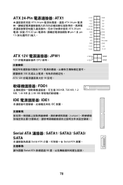
ATX 24-Pin ATX1 ATX 24-pin ATX 24-pin ATX 20-pin ATX 20-pin pin 1 及 pin 13 +3.3V +12V +12V 5VSB PWR OK GND +5V GND +5V GND +3.3V +3.3V ATX 12V JPW1 +12V 12V CPU 使用。 +12V ATX 350 ATX 12V 18 安培。 FDD1 360 KB, 720 KB, 1.2 MB, 1.44 MB 及 2.88 MB IDE IDE1 IDE 裝置。 Jumper GND +5V +5V +5V Res GND GND GND PS-ON# GND -12V +3.3V GND GND Serial ATA 連接器: SATA1/ SATA2/ SATA3/ SATA Serial ATA Serial ATA Serial ATA 90 70
ATX 24-Pin ATX1 ATX 24-pin ATX 24-pin ATX 20-pin ATX 20-pin pin 1 及 pin 13 +3.3V +12V +12V 5VSB PWR OK GND +5V GND +5V GND +3.3V +3.3V ATX 12V JPW1 +12V 12V CPU 使用。 +12V ATX 350 ATX 12V 18 安培。 FDD1 360 KB, 720 KB, 1.2 MB, 1.44 MB 及 2.88 MB IDE IDE1 IDE 裝置。 Jumper GND +5V +5V +5V Res GND GND GND PS-ON# GND -12V +3.3V GND GND Serial ATA 連接器: SATA1/ SATA2/ SATA3/ SATA Serial ATA Serial ATA Serial ATA 90 70
