User Guide
Page 8
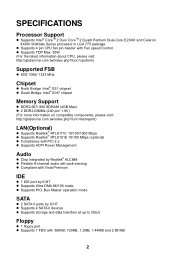
... pin-header with Fan speed Control l Supports TDP Max. 95W (For the latest information about CPU, please visit: http://global.msi.com.tw/index.php?func=cpuform) Supported FSB l 800/ 1066/ 1333 MHz Chipset l North Bridge: Intel® G31 chipset l South Bridge: Intel® ... Memory Support l DDR2 667/ 800 SDRAM (4GB Max) l 2 DDR2 DIMMs (240 pin/ 1.8V) (For more information on compatible components, please visit: http://global.msi.com.tw/index.php?func=testreport) LAN(Optional) l Supports Realtek® RTL8111C 10/100/1000 Mbps l Supports Realtek® RTL8101E 10/100 Mbps (optional) l Compliance...
... pin-header with Fan speed Control l Supports TDP Max. 95W (For the latest information about CPU, please visit: http://global.msi.com.tw/index.php?func=cpuform) Supported FSB l 800/ 1066/ 1333 MHz Chipset l North Bridge: Intel® G31 chipset l South Bridge: Intel® ... Memory Support l DDR2 667/ 800 SDRAM (4GB Max) l 2 DDR2 DIMMs (240 pin/ 1.8V) (For more information on compatible components, please visit: http://global.msi.com.tw/index.php?func=testreport) LAN(Optional) l Supports Realtek® RTL8111C 10/100/1000 Mbps l Supports Realtek® RTL8101E 10/100 Mbps (optional) l Compliance...
User Guide
Page 10
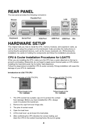
... load plate. 6. While doing the installation, be careful in the socket housing frame. Introduction to prevent overheating. Before you how to install the CPU, memory modules, and expansion cards, as well as the mouse, keyboard, etc. Remove the cap from damage. Open the load lever. 5.... Be sure to install the CPU & cooler correctly. CPU & Cooler Installation Procedures for LGA775 When you are installing the CPU, make sure the CPU has a cooler attached on CPU before installing the heat sink/cooler fan for correct mating, put down the...
... load plate. 6. While doing the installation, be careful in the socket housing frame. Introduction to prevent overheating. Before you how to install the CPU, memory modules, and expansion cards, as well as the mouse, keyboard, etc. Remove the cap from damage. Open the load lever. 5.... Be sure to install the CPU & cooler correctly. CPU & Cooler Installation Procedures for LGA775 When you are installing the CPU, make sure the CPU has a cooler attached on CPU before installing the heat sink/cooler fan for correct mating, put down the...
User Guide
Page 11
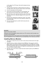
... load plate, and then secure the lever with the plastic cap covered to confirm that the alignment keys are matched. 7. The appearance of your CPU socket pin with the hook under retention tab. 10. You can barely see the golden finger if the memory module is properly inserted in BIOS... Installing Memory Modules 1. Press down the cooler until the golden finger on it in until its four clips get wedged into the holes of the CPU base. Insert the memory module vertically into the socket. Press the four hooks down to lock the hooks. 12. on the center and will automatically...
... load plate, and then secure the lever with the plastic cap covered to confirm that the alignment keys are matched. 7. The appearance of your CPU socket pin with the hook under retention tab. 10. You can barely see the golden finger if the memory module is properly inserted in BIOS... Installing Memory Modules 1. Press down the cooler until the golden finger on it in until its four clips get wedged into the holes of the CPU base. Insert the memory module vertically into the socket. Press the four hooks down to lock the hooks. 12. on the center and will automatically...
User Guide
Page 12
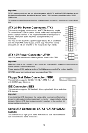
...3V +3.3V GND +5V +5V +5V Res GND GND GND PS-ON# GND -12V +3.3V ATX 12V Power Connector: JPW1 +12V GND This 12V power connector is used to provide power to the CPU. +12V GND Important: Make sure that all the connectors are aligned. Then push down the power ...or separately to IDE device documentation supplied by setting jumpers. To enable successful system boot-up, always insert the memory modules into the connector. ATX 24-Pin Power Connector: ATX1 This connector allows you like to ensure stable operation of 350 watts (and above) is inserted in the DDR2...
...3V +3.3V GND +5V +5V +5V Res GND GND GND PS-ON# GND -12V +3.3V ATX 12V Power Connector: JPW1 +12V GND This 12V power connector is used to provide power to the CPU. +12V GND Important: Make sure that all the connectors are aligned. Then push down the power ...or separately to IDE device documentation supplied by setting jumpers. To enable successful system boot-up, always insert the memory modules into the connector. ATX 24-Pin Power Connector: ATX1 This connector allows you like to ensure stable operation of 350 watts (and above) is inserted in the DDR2...
User Guide
Page 13
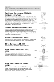
...: Please do not fold the Serial ATA cable into 90-degree angle. the black wire is compliant with speed sensor to take advantage of the CPU fan control. The JFP1 is Ground and should be connected to GND. Fan Power Connectors: CPUFAN1, SYSFAN1, SYSFAN2 The fan power connectors support system cooling...
...: Please do not fold the Serial ATA cable into 90-degree angle. the black wire is compliant with speed sensor to take advantage of the CPU fan control. The JFP1 is Ground and should be connected to GND. Fan Power Connectors: CPUFAN1, SYSFAN1, SYSFAN2 The fan power connectors support system cooling...
User Guide
Page 16
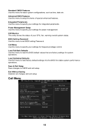
... items of your settings for frequency/voltage control. Exit Without Saving Abandon all changes and exit setup. Cell Menu Use this menu to specify your CPU, fan, warning overall system status. Load Fail-Safe Defaults Use this menu to set BIOS setting Password. Power Management Setup Use this menu to CMOS...
... items of your settings for frequency/voltage control. Exit Without Saving Abandon all changes and exit setup. Cell Menu Use this menu to specify your CPU, fan, warning overall system status. Load Fail-Safe Defaults Use this menu to set BIOS setting Password. Power Management Setup Use this menu to CMOS...
User Guide
Page 17
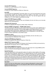
...this item will remove (turn off) clocks from empty DIMM and PCI slots to Enabled for EMI reduction. 11 Adjusted CPU Frequency It shows the adjusted CPU frequency (FSB x Ratio). Adjust PCI-E Frequency (MHz) This item allows you to set to minimize the electromagnetic interference ... system stability and performance. Setting to [By SPD] enables DRAM CAS# Latency automatically to [Disable], this field. Spread Spectrum When the motherboard's clock generator pulses, the extreme values (spikes) of Spread Spectrum for EMI reduction. Read-only. But if you are plagued by EMI...
...this item will remove (turn off) clocks from empty DIMM and PCI slots to Enabled for EMI reduction. 11 Adjusted CPU Frequency It shows the adjusted CPU frequency (FSB x Ratio). Adjust PCI-E Frequency (MHz) This item allows you to set to minimize the electromagnetic interference ... system stability and performance. Setting to [By SPD] enables DRAM CAS# Latency automatically to [Disable], this field. Spread Spectrum When the motherboard's clock generator pulses, the extreme values (spikes) of Spread Spectrum for EMI reduction. Read-only. But if you are plagued by EMI...
User Guide
Page 64
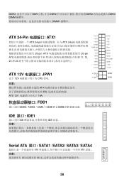
DDR2 DDR DDR2 DDR2 DDR2 DIMM DIMM1 ATX 24-Pin ATX1 ATX 24-pin ATX 24-pin 20-pin ATX 20-pin ATX 1 到 13 11, 12, 23 和 24 +3.3V +12V +12V 5VSB PWR OK GND +5V GND +5V GND +3.3V +3.3V ATX 12V JPW1 +12V 这个 12V CPU 供电. +12V ATX 350 ATX 12V 18A. FDD1 360KB, 720KB, 1.2MB, 1.44MB 和 2.88MB IDE 接口: IDE1 IDE IDE GND +5V +5V +5V Res GND GND GND PS-ON# GND -12V +3.3V GND GND Serial ATA 接口: SATA1 /SATA2/ SATA3/ SATA4 ATA ATA ATA 90 58
DDR2 DDR DDR2 DDR2 DDR2 DIMM DIMM1 ATX 24-Pin ATX1 ATX 24-pin ATX 24-pin 20-pin ATX 20-pin ATX 1 到 13 11, 12, 23 和 24 +3.3V +12V +12V 5VSB PWR OK GND +5V GND +5V GND +3.3V +3.3V ATX 12V JPW1 +12V 这个 12V CPU 供电. +12V ATX 350 ATX 12V 18A. FDD1 360KB, 720KB, 1.2MB, 1.44MB 和 2.88MB IDE 接口: IDE1 IDE IDE GND +5V +5V +5V Res GND GND GND PS-ON# GND -12V +3.3V GND GND Serial ATA 接口: SATA1 /SATA2/ SATA3/ SATA4 ATA ATA ATA 90 58
User Guide
Page 68
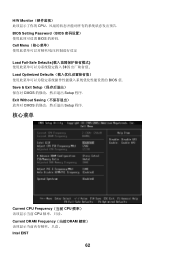
Save & Exit Setup CMOS Setup 程序. Cell Menu Load Fail-Safe Defaults BIOS Load Optimized Defaults BIOS 值. Exit Without Saving CMOS Setup 程序. 核心菜单 Current CPU Frequency(当前 CPU CPU Current DRAM Frequency(当前 DRAM Intel EIST 62 H/W Monitor CPU BIOS Setting Password(BIOS BIOS 的密码.
Save & Exit Setup CMOS Setup 程序. Cell Menu Load Fail-Safe Defaults BIOS Load Optimized Defaults BIOS 值. Exit Without Saving CMOS Setup 程序. 核心菜单 Current CPU Frequency(当前 CPU CPU Current DRAM Frequency(当前 DRAM Intel EIST 62 H/W Monitor CPU BIOS Setting Password(BIOS BIOS 的密码.
User Guide
Page 76
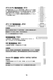
ATX 24-Pin ATX1 ATX 24-pin ATX 24-pin ATX 20-pin ATX 20-pin pin 1 及 pin 13 +3.3V +12V +12V 5VSB PWR OK GND +5V GND +5V GND +3.3V +3.3V ATX 12V JPW1 +12V 12V CPU 使用。 +12V ATX 350 ATX 12V 18 安培。 FDD1 360 KB, 720 KB, 1.2 MB, 1.44 MB 及 2.88 MB IDE IDE1 IDE 裝置。 Jumper GND +5V +5V +5V Res GND GND GND PS-ON# GND -12V +3.3V GND GND Serial ATA 連接器: SATA1/ SATA2/ SATA3/ SATA Serial ATA Serial ATA Serial ATA 90 70
ATX 24-Pin ATX1 ATX 24-pin ATX 24-pin ATX 20-pin ATX 20-pin pin 1 及 pin 13 +3.3V +12V +12V 5VSB PWR OK GND +5V GND +5V GND +3.3V +3.3V ATX 12V JPW1 +12V 12V CPU 使用。 +12V ATX 350 ATX 12V 18 安培。 FDD1 360 KB, 720 KB, 1.2 MB, 1.44 MB 及 2.88 MB IDE IDE1 IDE 裝置。 Jumper GND +5V +5V +5V Res GND GND GND PS-ON# GND -12V +3.3V GND GND Serial ATA 連接器: SATA1/ SATA2/ SATA3/ SATA Serial ATA Serial ATA Serial ATA 90 70
User Guide
Page 77
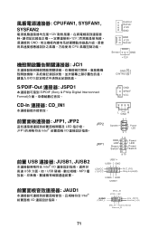
... + -- + -+ HDD LED Power LED Reset Switch Power Switch 9 10 USB1+ USB1- GND (2)VCC (1 )VC C N.C.(10) Key,no pin(9) USB0- CPUFAN1, SYSFAN1, SYSFAN2 12V 12V GND CPU JCI1 BIOS Control Sensor +12V GND GND +12V Sensor Sensor GND +12V GND 2 CINTRU 1 S/PDIF-Out 連接器: JSPD1 S/PDIF (Sony & Philip Digital Interconnect...
... + -- + -+ HDD LED Power LED Reset Switch Power Switch 9 10 USB1+ USB1- GND (2)VCC (1 )VC C N.C.(10) Key,no pin(9) USB0- CPUFAN1, SYSFAN1, SYSFAN2 12V 12V GND CPU JCI1 BIOS Control Sensor +12V GND GND +12V Sensor Sensor GND +12V GND 2 CINTRU 1 S/PDIF-Out 連接器: JSPD1 S/PDIF (Sony & Philip Digital Interconnect...
User Guide
Page 80
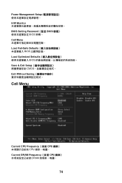
Power Management Setup H/W Monitor BIOS Setting Password(設定 BIOS BIOS 密碼。 Cell Menu Load Fail-Safe Defaults BIOS Load Optimized Defaults BIOS Save & Exit Setup CMOS Exit Without Saving Cell Menu Current CPU Frequency(目前 CPU CPU Current DRAM Frequency(目前 CPU DRAM 74
Power Management Setup H/W Monitor BIOS Setting Password(設定 BIOS BIOS 密碼。 Cell Menu Load Fail-Safe Defaults BIOS Load Optimized Defaults BIOS Save & Exit Setup CMOS Exit Without Saving Cell Menu Current CPU Frequency(目前 CPU CPU Current DRAM Frequency(目前 CPU DRAM 74
User Guide
Page 92
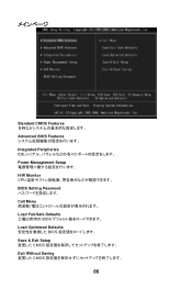
Standard CMOS Features Advanced BIOS Features Integrated Peripherals IDE I/O Power Management Setup H/W Monitor CPU BIOS Setting Password Cell Menu Load Fail-Safe Defaults BIOS Load Optimized Defaults BIOS Save & Exit Setup CMOS Exit Without Saving CMOS 86
Standard CMOS Features Advanced BIOS Features Integrated Peripherals IDE I/O Power Management Setup H/W Monitor CPU BIOS Setting Password Cell Menu Load Fail-Safe Defaults BIOS Load Optimized Defaults BIOS Save & Exit Setup CMOS Exit Without Saving CMOS 86

