Hardware Maintenance Manual
Page 4
1070 Backup battery 64 1080 Keyboard 65 1090 Keyboard bezel assembly and power button sub card 68 1100 Thermal fan assembly 70 1110 Microprocessor 72 1120 System board assembly and VGA sub card . 73 ...
1070 Backup battery 64 1080 Keyboard 65 1090 Keyboard bezel assembly and power button sub card 68 1100 Thermal fan assembly 70 1110 Microprocessor 72 1120 System board assembly and VGA sub card . 73 ...
Hardware Maintenance Manual
Page 30
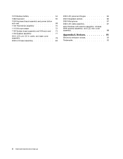
... nonsupported device • Forgotten computer password (making the computer unusable) • Sticky keys caused by spilling a liquid onto the keyboard • Use of an incorrect ac power adapter on laptop products The following symptoms might indicate damage caused by nonwarranted activities: &#... this program, see the help information system. Lenovo Solution Center The Lenovo Solution Center program enables you to test only ThinkPad products. Note: The Lenovo Solution Center program is available only on the screen. To run the Lenovo Solution Center program, click Start ➙ Control...
... nonsupported device • Forgotten computer password (making the computer unusable) • Sticky keys caused by spilling a liquid onto the keyboard • Use of an incorrect ac power adapter on laptop products The following symptoms might indicate damage caused by nonwarranted activities: &#... this program, see the help information system. Lenovo Solution Center The Lenovo Solution Center program enables you to test only ThinkPad products. Note: The Lenovo Solution Center program is available only on the screen. To run the Lenovo Solution Center program, click Start ➙ Control...
Hardware Maintenance Manual
Page 39
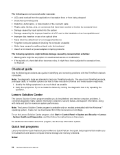
... the LCD cover. • Turn on the hard disk. • The system is restored from sleep mode and resume operation, do any operation with the keyboard, the TrackPoint, the hard disk, the parallel connector, or the diskette drive within that action. • Closing the lid. • Pressing the power button. Wait...
... the LCD cover. • Turn on the hard disk. • The system is restored from sleep mode and resume operation, do any operation with the keyboard, the TrackPoint, the hard disk, the parallel connector, or the diskette drive within that action. • Closing the lid. • Pressing the power button. Wait...
Hardware Maintenance Manual
Page 46
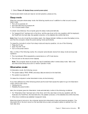
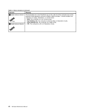
Table 5. Status indicators (continued) Indicator Meaning 3 System status indicator 4 System status indicator The illuminated dot in the ThinkPad logo on the outer lid of the computer and on the keyboard bezel assembly works as a system status indicator: it shows whether the computer is in sleep, hibernation, or normal mode. • Red: The computer...
Table 5. Status indicators (continued) Indicator Meaning 3 System status indicator 4 System status indicator The illuminated dot in the ThinkPad logo on the outer lid of the computer and on the keyboard bezel assembly works as a system status indicator: it shows whether the computer is in sleep, hibernation, or normal mode. • Red: The computer...

Hardware Maintenance Manual
Page 47
...the camera and audio settings from this key to turn on the sound, press this key, the computer display becomes brighter. (F8) © Copyright Lenovo 2012 41 Switching the display output location (F6) Press this key to turn up key. Chapter 6. Table 6. Speaker volume down (F2) Press this ...key to mute or unmute all of the keyboard. Launching the camera and audio settings (F5) Press this key, the computer display becomes dimmer. Note: To switch between the computer display and an ...
...the camera and audio settings from this key to turn on the sound, press this key, the computer display becomes brighter. (F8) © Copyright Lenovo 2012 41 Switching the display output location (F6) Press this key to turn up key. Chapter 6. Table 6. Speaker volume down (F2) Press this ...key to mute or unmute all of the keyboard. Launching the camera and audio settings (F5) Press this key, the computer display becomes dimmer. Note: To switch between the computer display and an ...
Hardware Maintenance Manual
Page 51
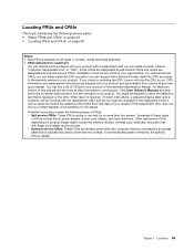
...is your product and are shipped with finger print reader and touch pad. - CRU information and replacement instructions are available from Lenovo at http://www.lenovo.com/support. ThinkPad computers contain the following service parts: • "Major FRUs and CRUs" on page 46 • "Locating FRUs and ..., and hard disk drive. You might include the memory module, wireless card, keyboard, and palm rest with your responsibility. Examples of these types of CRUs for the replacement CRU if Lenovo does not receive the defective CRU within the computer that are concealed by an ...
...is your product and are shipped with finger print reader and touch pad. - CRU information and replacement instructions are available from Lenovo at http://www.lenovo.com/support. ThinkPad computers contain the following service parts: • "Major FRUs and CRUs" on page 46 • "Locating FRUs and ..., and hard disk drive. You might include the memory module, wireless card, keyboard, and palm rest with your responsibility. Examples of these types of CRUs for the replacement CRU if Lenovo does not receive the defective CRU within the computer that are concealed by an ...
Hardware Maintenance Manual
Page 52
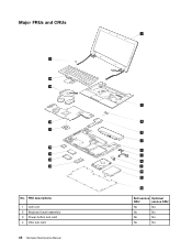
Major FRUs and CRUs 21 20 19 18 17 16 15 14 13 No. FRU descriptions 1 LCD unit 2 Keyboard bezel assembly 3 Power button sub card 4 VGA sub card 46 Hardware Maintenance Manual 1 2 3 4 5 6 7 8 9 10 11 12 Self-service Optional CRU service CRU No No No No No No No No
Major FRUs and CRUs 21 20 19 18 17 16 15 14 13 No. FRU descriptions 1 LCD unit 2 Keyboard bezel assembly 3 Power button sub card 4 VGA sub card 46 Hardware Maintenance Manual 1 2 3 4 5 6 7 8 9 10 11 12 Self-service Optional CRU service CRU No No No No No No No No
Hardware Maintenance Manual
Page 53
... (on some models) 15 mSATA solid-state drive (on some models) 16 Wireless LAN card 17 Microprocessor 18 System board 19 Thermal fan assembly 20 Keyboard 21 TrackPoint cap Self-service Optional CRU service CRU Yes No No No No No No No Yes No Yes No Yes No Yes No...
... (on some models) 15 mSATA solid-state drive (on some models) 16 Wireless LAN card 17 Microprocessor 18 System board 19 Thermal fan assembly 20 Keyboard 21 TrackPoint cap Self-service Optional CRU service CRU Yes No No No No No No No Yes No Yes No Yes No Yes No...
Hardware Maintenance Manual
Page 71
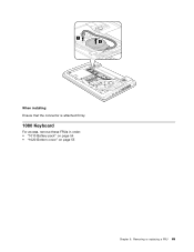
Removing or replacing a FRU 65 1 2 When installing: Ensure that the connector is attached firmly. 1080 Keyboard For access, remove these FRUs in order: • "1010 Battery pack" on page 54 • "1020 Bottom cover" on page 55 Chapter 9.
Removing or replacing a FRU 65 1 2 When installing: Ensure that the connector is attached firmly. 1080 Keyboard For access, remove these FRUs in order: • "1010 Battery pack" on page 54 • "1020 Bottom cover" on page 55 Chapter 9.
Hardware Maintenance Manual
Page 72
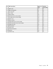
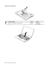
Removal steps of keyboard 1 1 Step 1 Screw (quantity) M2 × 6 mm, flat-head, nylon-coated (2) Color Black Torque 0.181 Nm (1.85 kgfcm) 3 2 2 66 Hardware Maintenance Manual
Removal steps of keyboard 1 1 Step 1 Screw (quantity) M2 × 6 mm, flat-head, nylon-coated (2) Color Black Torque 0.181 Nm (1.85 kgfcm) 3 2 2 66 Hardware Maintenance Manual
Hardware Maintenance Manual
Page 73
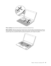
Chapter 9. Removing or replacing a FRU 67 7 8 5 6 4 When installing: Ensure that the hooks on the front edge of the keyboard is housed firmly, gently press the keys with your palms to slide the keyboard towards you until it snaps into position. When the front edge of the keyboard are attached firmly. When installing: Attach the keyboard so that the keyboard connectors are under the frame as shown in the following illustration.
Chapter 9. Removing or replacing a FRU 67 7 8 5 6 4 When installing: Ensure that the hooks on the front edge of the keyboard is housed firmly, gently press the keys with your palms to slide the keyboard towards you until it snaps into position. When the front edge of the keyboard are attached firmly. When installing: Attach the keyboard so that the keyboard connectors are under the frame as shown in the following illustration.
Hardware Maintenance Manual
Page 74
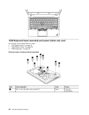
1090 Keyboard bezel assembly and power button sub card For access, remove these FRUs in order: • "1010 Battery pack" on page 54 • "1020 Bottom cover" on page 55 • "1080 Keyboard" on page 65 Removal steps of keyboard bezel assembly 1 1 1 1 1 1 1 1 1 1 1 Step 1 Screw (quantity) M2 × 6 mm, flat-head, nylon-coated (11) Color Black Torque 0.181 Nm (1.85 kgfcm) 68 Hardware Maintenance Manual
1090 Keyboard bezel assembly and power button sub card For access, remove these FRUs in order: • "1010 Battery pack" on page 54 • "1020 Bottom cover" on page 55 • "1080 Keyboard" on page 65 Removal steps of keyboard bezel assembly 1 1 1 1 1 1 1 1 1 1 1 Step 1 Screw (quantity) M2 × 6 mm, flat-head, nylon-coated (11) Color Black Torque 0.181 Nm (1.85 kgfcm) 68 Hardware Maintenance Manual
Hardware Maintenance Manual
Page 76
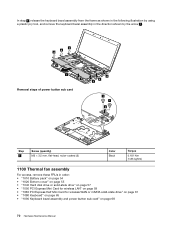
... assembly from the frame as shown in the following illustration by using a plastic pry tool, and remove the keyboard bezel assembly in the direction shown by the arrow 7 . 6 6 6 6 7 6 Removal steps of power button sub card 6 6 6 2 Step 1 Screw (quantity) M2 × 3.5 mm, flat-head, nylon-... wireless LAN" on page 59 • "1060 PCI Express Half Mini Card for wireless WAN or mSATA solid-state drive" on page 61 • "1080 Keyboard" on page 65 • "1090 Keyboard bezel assembly and power button sub card" on page 68 70 Hardware Maintenance Manual
... assembly from the frame as shown in the following illustration by using a plastic pry tool, and remove the keyboard bezel assembly in the direction shown by the arrow 7 . 6 6 6 6 7 6 Removal steps of power button sub card 6 6 6 2 Step 1 Screw (quantity) M2 × 3.5 mm, flat-head, nylon-... wireless LAN" on page 59 • "1060 PCI Express Half Mini Card for wireless WAN or mSATA solid-state drive" on page 61 • "1080 Keyboard" on page 65 • "1090 Keyboard bezel assembly and power button sub card" on page 68 70 Hardware Maintenance Manual
Hardware Maintenance Manual
Page 80
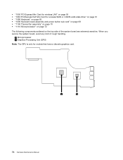
... b Graphics Processing Unit (GPU) Note: The GPU is only for wireless WAN or mSATA solid-state drive" on page 61 • "1080 Keyboard" on page 65 • "1090 Keyboard bezel assembly and power button sub card" on page 68 • "1100 Thermal fan assembly" on page 70 • "1110 Microprocessor" on page...
... b Graphics Processing Unit (GPU) Note: The GPU is only for wireless WAN or mSATA solid-state drive" on page 61 • "1080 Keyboard" on page 65 • "1090 Keyboard bezel assembly and power button sub card" on page 68 • "1100 Thermal fan assembly" on page 70 • "1110 Microprocessor" on page...
Hardware Maintenance Manual
Page 83
..." on page 59 • "1060 PCI Express Half Mini Card for wireless WAN or mSATA solid-state drive" on page 61 • "1080 Keyboard" on page 65 • "1090 Keyboard bezel assembly and power button sub card" on page 68 • "1100 Thermal fan assembly" on page 70 • "1110 Microprocessor" on...
..." on page 59 • "1060 PCI Express Half Mini Card for wireless WAN or mSATA solid-state drive" on page 61 • "1080 Keyboard" on page 65 • "1090 Keyboard bezel assembly and power button sub card" on page 68 • "1100 Thermal fan assembly" on page 70 • "1110 Microprocessor" on...

Hardware Maintenance Manual
Page 85
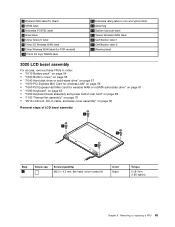
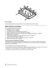
• "1050 PCI Express Mini Card for wireless LAN" on page 59 • "1060 PCI Express Half Mini Card for wireless WAN or mSATA solid-state drive" on page 61 • "1080 Keyboard" on page 65 • "1090 Keyboard bezel assembly and power button sub card" on page 68 • "1100 Thermal fan assembly" on page 70 • "1120 System board assembly and VGA sub card" on page 73 Removal steps of LCD unit 1 1 11 1 11 1 3 2 When installing: • Ensure that the cables are attached to the cable guides firmly. Removing or replacing a FRU 79 Chapter 9.
• "1050 PCI Express Mini Card for wireless LAN" on page 59 • "1060 PCI Express Half Mini Card for wireless WAN or mSATA solid-state drive" on page 61 • "1080 Keyboard" on page 65 • "1090 Keyboard bezel assembly and power button sub card" on page 68 • "1100 Thermal fan assembly" on page 70 • "1120 System board assembly and VGA sub card" on page 73 Removal steps of LCD unit 1 1 11 1 11 1 3 2 When installing: • Ensure that the cables are attached to the cable guides firmly. Removing or replacing a FRU 79 Chapter 9.
Hardware Maintenance Manual
Page 89
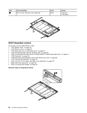
..." on page 59 • "1060 PCI Express Half Mini Card for wireless WAN or mSATA solid-state drive" on page 61 • "1080 Keyboard" on page 65 • "1090 Keyboard bezel assembly and power button sub card" on page 68 • "1100 Thermal fan assembly" on page 70 • "2010 LCD unit...
..." on page 59 • "1060 PCI Express Half Mini Card for wireless WAN or mSATA solid-state drive" on page 61 • "1080 Keyboard" on page 65 • "1090 Keyboard bezel assembly and power button sub card" on page 68 • "1100 Thermal fan assembly" on page 70 • "2010 LCD unit...
Hardware Maintenance Manual
Page 90
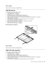
... the panel. • Do not touch or apply any kind of pressure to the printed circuit board. 84 Hardware Maintenance Manual Do not hold the edges of your hands. 2 2 2 2 2 2 2 2 22 When installing: Ensure that all the latches are very sensitive. Then secure the bezel with both of the panel with ... on page 59 • "1060 PCI Express Half Mini Card for wireless WAN or mSATA solid-state drive" on page 61 • "1080 Keyboard" on page 65 • "1090 Keyboard bezel assembly and power button sub card" on page 68 • "1100 Thermal fan assembly" on page 70 • "2010 LCD unit...
... the panel. • Do not touch or apply any kind of pressure to the printed circuit board. 84 Hardware Maintenance Manual Do not hold the edges of your hands. 2 2 2 2 2 2 2 2 22 When installing: Ensure that all the latches are very sensitive. Then secure the bezel with both of the panel with ... on page 59 • "1060 PCI Express Half Mini Card for wireless WAN or mSATA solid-state drive" on page 61 • "1080 Keyboard" on page 65 • "1090 Keyboard bezel assembly and power button sub card" on page 68 • "1100 Thermal fan assembly" on page 70 • "2010 LCD unit...
Hardware Maintenance Manual
Page 92
..." on page 59 • "1060 PCI Express Half Mini Card for wireless WAN or mSATA solid-state drive" on page 61 • "1080 Keyboard" on page 65 • "1090 Keyboard bezel assembly and power button sub card" on page 68 • "1100 Thermal fan assembly" on page 70 • "2010 LCD unit...
..." on page 59 • "1060 PCI Express Half Mini Card for wireless WAN or mSATA solid-state drive" on page 61 • "1080 Keyboard" on page 65 • "1090 Keyboard bezel assembly and power button sub card" on page 68 • "1100 Thermal fan assembly" on page 70 • "2010 LCD unit...
Hardware Maintenance Manual
Page 93
..." on page 59 • "1060 PCI Express Half Mini Card for wireless WAN or mSATA solid-state drive" on page 61 • "1080 Keyboard" on page 65 • "1090 Keyboard bezel assembly and power button sub card" on page 68 • "1100 Thermal fan assembly" on page 70 • "2010 LCD unit... wireless LAN" on page 59 • "1060 PCI Express Half Mini Card for wireless WAN or mSATA solid-state drive" on page 61 • "1080 Keyboard" on page 65 • "1090 Keyboard bezel assembly and power button sub card" on page 68 Chapter 9. Removing or replacing a FRU 87
..." on page 59 • "1060 PCI Express Half Mini Card for wireless WAN or mSATA solid-state drive" on page 61 • "1080 Keyboard" on page 65 • "1090 Keyboard bezel assembly and power button sub card" on page 68 • "1100 Thermal fan assembly" on page 70 • "2010 LCD unit... wireless LAN" on page 59 • "1060 PCI Express Half Mini Card for wireless WAN or mSATA solid-state drive" on page 61 • "1080 Keyboard" on page 65 • "1090 Keyboard bezel assembly and power button sub card" on page 68 Chapter 9. Removing or replacing a FRU 87


